


A variety of accuracy-relevant information describes the accuracy, which itself does not exist in the way we use it in everyday language. About 68.27% of the devices used by the user comply with the typical value of "accuracy".
Paradoxically, a pressure sensor with 0.5% error at maximum non-linearity after limit settings is as accurate as a pressure sensor with 0.1% after non-linearity after minimum settings.
The following describes properties that can lead to deviations in the measurement data. It should be noted that their use is not standardized. This means, for example, that three identical specifications for non-linearity can describe three completely different accuracies.
Nonlinearity
The most frequently mentioned specification of accuracy is non-linearity. This defines the most extreme deviation between the characteristic curve and the reference line. After setting the limit point, the reference straight line goes through the beginning and end of the characteristic curve in the case of non-linearity. In comparison, there is the BFSL (Best Fit Straight Line) method, in which the reference line is aligned in such a way that the maximum positive and maximum negative deviation is the same.
The non-linearity after limit setting offers the largest possible error in absolute terms, but it is the easiest for users to understand, even if the minimum value setting provides a more precise value in most cases.
Measurement error
The measurement deviation that comes closest to the true value is the measurement deviation. The reason for this is the ability to read the following immediately:
- Measurement deviation at the beginning and end of the measuring range
- Nonlinearity
- Hysteresis
- Non-repeatability
The largest difference between the actual and the ideal characteristic is the measurement deviation. The hysteresis defines the maximum variance in up and down gears.
Unfortunately, hysteresis and non-repeatability can neither be completely eliminated nor minimized.
Fix inaccuracies
Remove zero error
The zero point error can be read in the depressurized state. This is entered as an offset in its evaluation unit.
Remove span errors
In order to eliminate the span error, it is assumed that the pressure at the end of the measuring range has been approached exactly. This requires a pressure reference that is at least three times more accurate than the desired accuracy.
Remove non-linearity
Non-linearity can be minimized by, for example, using support points in the downstream electronics to calculate errors. However, this technique requires an extremely precise standard.
The accuracy of sensors can be affected by a variety of factors. For this reason, a comprehensive analysis is recommended in advance. In this way, possible sources of error can be identified and eliminated in advance. This applies to the installation of the measuring device itself, but also in advance to the circumstances under which the accuracy in the data sheet was generated.
In conclusion, the effort you put into the accuracy of your gauges is well worth it. Not only does it increase security, but it also delivers precision and flawless continuity.
Temperature coefficient
All accuracy specifications as described here have been defined at room temperature. However, if you want to measure at temperatures that are above or below room temperature, you also have to calculate the temperature error, also known as the temperature coefficient. A measuring device that offers sufficient accuracy at room temperature can show an error that is twice as large from as little as 10 K.
Long term drift
What happens between the production site of a measuring device and its arrival at the user? Even storage and transport can permanently manipulate the accuracy. The meter can also change over time due to possible magnetic interference or continuous vibrations at the measurement site. For this reason, manufacturers recommend annual calibration to record the so-called drift, the change in the device.
- Pressure ranges 1.6, 3, 10, 15, 30, 80, 125, 250, 350 bar
- Absolute reference
- 0.2 to 4.7 Vdc voltage output
- Total accuracy including thermal effects ± 1% span
- Frequency response to 1 kHz
- 316L Stainless steel construction
- Compensated temperature range -40 °C to 125 °C / Short term use from -55 °C to 150 °C
 Datasheet Datasheet |
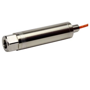
- Race proven technology
- High temperature capability to 350°F (175°C)
- Amplified or millivolt output
- Stainless steel or titanium construction
- Fully EMC protected
- Flexible mechanical/electrical interface options
| Datasheet |
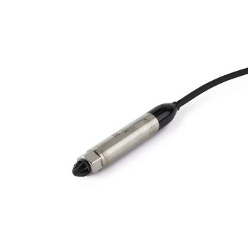
Druck’s 4400T is the new pinnacle motorsport sensor, combining pressure and temperature measurements. Key features of the 4400T include:
- Race proven technology
- High temperature capability to 185°C
- 14.5 mm diameter
- Amplified output
- Stainless steel construction
- Fully EMC protected
- PT1000 temperature probe
| Datasheet |
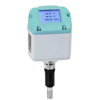
- 3 in 1 sensor: absolute pressure, temperature and humidity in the room
- Modbus-RTU, Ethernet or M-Bus interface
- Alarm relay – limit value adjustable via buttons (max 60 VDC, 0.5 A)
- Optional: 2 x 4...20 mA analogue outputs, 2 x alarm relays, e.g., for dew point and temperature
| Datasheet |
| User Manual |
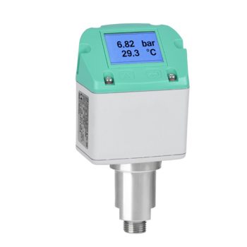
- 2 in 1 sensor: Pressure and temperature
- Wettedparts made of stainless steel for universal use in gases and liquids
- Easy integration into control systems, process control technology and energy management systems via digital interfaces
- Modbus-RTU, Ethernet or M-Bus interface
- Alarm relay – limit value adjustable via buttons (max 60 VDC, 0.5 A)
- Optional: 2 x 4...20 mA analogue output, 2 x alarm relays for pressure and temperature
| Datasheet |
| User Manual |
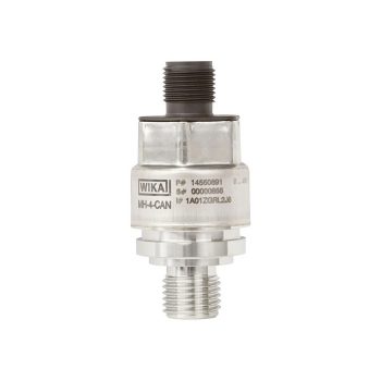
- For extreme operating conditions
- Signal stability thanks to CANopen®
- Reliable and accurate
- Customer-specific solutions
- High production capacities
| Datasheet |
| User Manual |
| User Manual |
| User Manual |
- Ranges from 70 mbar to 100 bar
- Total accuracy to ±0.1 % FS
- Stainless steel construction
- 3 V supply voltage
- Low power
- I2C digital output
- Sleep mode
- Hazardous area certifications
- Excellent long-term stability
| Datasheet |
|
User Manual
|
- Ranges from 350 mbar to 70 bar
- Total accuracy to ±0.1 % FS
- Stainless steel or titanium construction
- Wide temperature range -40 °C to 80 °C
- Low power
- Customer set filter setting
- Excellent long-term stability
- Customizable and reconfigurable output formats
| Datasheet |
|
User Manual
|
- Ranges from 200 mbar to 700 bar
- Total accuracy to ±0.1 % FS
- Stainless steel construction
- Wide temperature range -40 °C to 125 °C
- Fast update rate 1 ms
- Customer set filter setting
- Baud rate upto 1000k bit/s
- Excellent long-term stability
| Datasheet |
|
User Manual
|
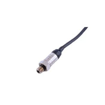
- Race proven technology
- High temperature capability to 175°C
- 12.5 mm diameter
- Amplified output
- Stainless steel construction
- Fully EMC protected
- Flexible mechanical/electrical interface options
| Datasheet |
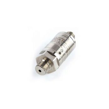
- High Precision, ±0.01% FS over compensated temperature range
- High Stability, ±100 ppm FS/year
- Wide temperature range, up to -40°C to +125°C (-40° to 257°F)
- Media isolated construction, suitable for use in harsh environments
- Multiple output configurations, RS-232, RS-485, USB 2.0, CAN Bus, frequency and diode (TTL)
- Wide selection of pressure and electrical connections to suit specific requirements
| Datasheet |
- output signal: RS485 with Modbus RTU protocol
- reset function
- nominal pressure: from 0 ... 100 mbar up to 0 ... 60 bar
- accuracy: 0,35% (opt. 0,25%) FSO
- output signal: RS485 mit Modbus RTU Protokoll
- ceramic diaphragm
 Datasheet Datasheet |
| User Manual |