


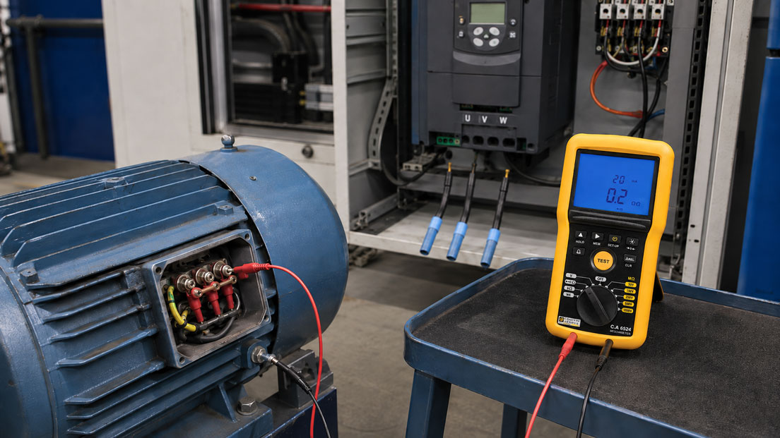
Insulation resistance measurement is one of the most important tests for damp, contaminated or fault-prone electric motors. It can provide indications of damaged winding insulation, conductive deposits, moisture ingress and faults in the motor cable.
However, particular care is required when the motor is supplied by a variable frequency drive. The DC test voltage of an insulation tester must not be applied uncontrollably to the drive output, EMC filters, temperature evaluation circuits, encoders or other electronic components. Otherwise, semiconductors, overvoltage protection circuits and sensitive inputs may be damaged.
Before testing, the exact test scope and electrical disconnection point must therefore be defined. Is only the motor to be assessed, only the motor cable, or the combination of motor and cable? This decision determines which conductors must be disconnected, connected together or grounded and how an abnormal measurement result can subsequently be narrowed down.
Suitable measuring instruments can be found in the ICS category Insulation Testers. Additional instruments for maintenance, machine testing and electrical troubleshooting are summarised under Electrical Measuring and Test Instruments.
Table of Contents
- What does an insulation test on a motor indicate?
- Why the variable frequency drive must be disconnected
- Safely shut down the drive and discharge the DC link
- Test the motor, cable or complete outgoing circuit?
- Disconnect sensors, brake and auxiliary circuits
- Correctly consider star and delta connections
- Select a suitable test voltage
- Perform the insulation test systematically
- Consider the temperature dependence of measured values
- Correctly assess the polarisation index and DAR
- Distinguish between limit values and trends
- Identify moisture, contamination and cable damage
- What an insulation test cannot detect
- Reconnection and functional checks
- Typical errors when testing motors
- Practical example: Earth fault indication on the variable frequency drive
- Which products and solutions are suitable?
- Conclusion
- Frequently asked questions
What does an insulation test on a motor indicate?
An insulation tester applies a defined DC voltage between active conductors and the grounded motor housing or protective conductor. The instrument calculates the insulation resistance from the test voltage and the resulting leakage current.
Intact, clean and dry winding insulation permits only a very small current to flow. Moisture, conductive dust, oil, damaged cables or aged insulating materials increase the leakage current and reduce the displayed resistance.
Typical test objectives include:
- windings against the motor housing and protective conductor,
- motor cable against the protective conductor and shield,
- individual phases against each other, provided they are electrically separated,
- heater, brake and auxiliary windings as separate circuits,
- comparison of the current condition with previous measurement results.
The insulation test primarily measures insulation against earth or between electrically separated winding sections. It does not provide complete proof that a motor is electrically and mechanically fault-free.
Why the variable frequency drive must be disconnected
A variable frequency drive contains power semiconductors, DC-link capacitors, voltage-limiting components, measuring circuits and often additional EMC components. These components are not automatically designed for a DC voltage applied externally by an insulation tester.
If the motor cable remains connected to the drive output during testing, the test voltage can enter the power electronics through the output terminals. Possible consequences include:
- damage to IGBT or MOSFET power stages,
- overloading of internal voltage-limiting components,
- damage to measuring and monitoring circuits,
- implausible or excessively low readings caused by parallel electronic paths,
- charging of DC-link and filter capacitors,
- subsequent drive failures that are not initially apparent.
The motor cable must therefore normally be disconnected from the output terminals of the variable frequency drive before insulation testing. The exact procedure must comply with the operating and maintenance instructions for the drive being used.
Insulation testing must also not be performed indiscriminately at the input or output terminals of a variable frequency drive. Some manufacturers describe specific test procedures for their equipment. These procedures are product-specific and must not be applied to other drives without verification.
Safely shut down the drive and discharge the DC link
Work on motors and variable frequency drives may only be performed by qualified electrical personnel and in accordance with the company’s electrical isolation procedure. Switching off the equipment using the control panel or the “Safe Torque Off” function alone does not ensure that all hazardous voltages have been removed.
Before opening and disconnecting the equipment, the following energy sources, among others, must be considered:
- mains supply to the variable frequency drive,
- separate control voltage, such as 24 V DC,
- common DC link or regenerative power supply,
- external braking resistor and brake chopper,
- auxiliary voltages for the brake, heater, fan or sensors,
- UPS, generator or emergency power supply,
- a mechanically driven motor with possible regenerative voltage generation.
After disconnecting the power supply, the discharge time specified by the drive manufacturer must be observed. The absence of voltage must then be verified at the relevant mains, DC-link and motor terminals using a suitable measuring instrument.
Permanent-magnet motors and certain synchronous machines can generate electrical voltage when moved. The drive must therefore be secured against unintended rotation. This applies, for example, to fans, pumps, lifts, conveyor systems and drives that can be turned backwards by a moving load.
Test the motor, cable or complete outgoing circuit?
Before connecting the insulation tester, it must be defined which part of the system is to be tested.
| Test scope | Electrical disconnection | Result |
|---|---|---|
| Motor and motor cable together | Motor cable disconnected from the variable frequency drive | Quick overall assessment of the motor outgoing circuit |
| Motor only | Motor cable disconnected at the motor and drive | Condition of the winding insulation and motor terminal board |
| Motor cable only | Cable disconnected at both ends | Insulation of the conductors, shield and cable run |
| Individual winding phase | Star or delta links removed | Targeted assessment of one winding group |
| Auxiliary circuit | Completely separated from the motor winding and electronics | Separate assessment of the heater, brake or auxiliary winding |
Testing the motor and cable together is suitable as an initial troubleshooting step. If the value is sufficiently high and stable, the complete outgoing circuit is initially considered unobjectionable with regard to earth insulation.
However, a low combined measurement does not indicate whether the fault is located in the motor, terminal box, plug connection or motor cable. The motor and cable must be tested separately to identify the fault location.
Disconnect sensors, brake and auxiliary circuits
Modern motors often contain additional electrical components alongside the power windings. These components must not accidentally be subjected to the test voltage intended for the motor winding.
The following connections in particular must be identified before testing:
- PTC or KTY temperature sensors,
- Pt100 or Pt1000 resistance thermometers,
- encoders and resolvers,
- electromagnetic holding brake,
- anti-condensation heater or standstill heater,
- forced-air fan and fan monitoring,
- vibration or bearing sensors,
- electronic motor protection modules,
- integrated connection or diagnostic electronics.
The auxiliary circuits must be separated from one another in accordance with the circuit diagram and tested according to their own specifications. A test voltage suitable for the power winding may already be destructive for a temperature sensor or encoder.
Particular care is required with temperature sensors connected directly to a drive or PLC input. Even if the drive’s power output has been disconnected, the test voltage can enter the control system through jointly routed sensor cables.
Correctly consider star and delta connections
The windings of a three-phase motor are normally connected in star or delta at the terminal board. As long as the links are installed, electrical connections exist between the individual winding phases.
Overall measurement against earth
For an overall test of the windings against the motor housing, the three line-conductor terminals may be connected together, depending on the manufacturer’s instructions, and tested against the grounded motor housing. This applies the test voltage to the complete main winding simultaneously.
Individual phases against earth
If the winding phases are to be assessed individually, the star or delta links must be removed. Each winding can then be tested separately while the other windings and the motor housing are grounded in accordance with the test instructions.
Testing between windings
A meaningful insulation measurement between two winding phases is only possible if they are electrically separated. With the star or delta links installed, the measuring instrument would detect a conductive connection through the normal winding resistance.
Before removing the links, their position and connection sequence must be clearly documented. After testing, they must be reinstalled using the specified contact surfaces, washers and tightening torques.
Select a suitable test voltage
The test voltage must not be selected solely based on routine practice. The decisive factors are the motor’s rated voltage, age, insulation system, condition, manufacturer specifications and the specific purpose of the test.
| Test object | Possible test-voltage range | Important note |
|---|---|---|
| Low-voltage motor | Frequently 500 or 1,000 V DC | The motor manufacturer and maintenance instructions are decisive |
| Motor cable up to 1 kV | Frequently 500 or 1,000 V DC | Check the cable type, connected components and applicable regulations |
| Sensitive control circuits | Possibly 50, 100 or 250 V DC | Only after approval for the respective circuit |
| Medium-voltage motor | Significantly higher test voltage depending on the motor | Specialised procedures and manufacturer specifications are required |
| Encoders and electronic sensors | No motor insulation-test voltage | Test separately in accordance with the manufacturer’s instructions |
A higher test voltage does not automatically produce a better result. It places greater stress on the insulation and may cause breakdown in pre-damaged, aged or damp windings.
For an unknown motor, the documentation should therefore be obtained first. If no clear specifications are available, a qualified electrical specialist or motor service provider must define the appropriate test procedure.
A high-voltage test using several kilovolts is not a normal extension of a maintenance test on a low-voltage motor. It requires suitable equipment, test procedures, protective measures and assessment criteria.
Perform the insulation test systematically
A suitable test procedure consists of several controlled steps:
- Identify the drive: Record the motor data, drive type, circuit diagram and connected auxiliary components.
- Disconnect all energy sources: Isolate the main and auxiliary supplies and secure them against reconnection.
- Observe the discharge time: Allow the DC link to discharge in accordance with the drive documentation.
- Verify the absence of voltage: Check the mains, DC-link, output and auxiliary terminals.
- Disconnect the motor cable from the drive: Fully disconnect U, V and W or T1, T2 and T3.
- Disconnect auxiliary circuits: Isolate sensors, brake, heater, encoder and forced-air fan.
- Define the test scope: Test the motor and cable together or separately.
- Document the motor condition: Record the winding temperature, ambient temperature, humidity and visible contamination.
- Set the test voltage: Consider the manufacturer’s approval and motor condition.
- Connect the test leads: Establish a secure, fixed connection to the winding and motor housing.
- Perform the test: Record the resistance, test duration, test voltage and time-dependent behaviour.
- Discharge the test object: Wait for the automatic discharge process and check for residual voltage.
- Narrow down abnormal results: Test the motor, cable and auxiliary circuits separately.
- Check the reconnection: Verify links, terminals, shielding, protective conductor and sensor cables.
The test terminals must not be touched or repositioned during testing. Windings and long cables behave capacitively and may retain a hazardous charge even after the test voltage has been switched off.
Consider the temperature dependence of measured values
The insulation resistance of a motor winding depends strongly on its temperature. A warm winding normally produces a significantly lower measured resistance than the same winding when cold.
The following is often used as an approximate rule of thumb:
If the temperature increases by 10 °C, the insulation resistance approximately halves.
If the temperature decreases by 10 °C, the insulation resistance approximately doubles.
This rule is suitable for an approximate assessment, but it is not a universal correction for every insulating material. The correction factors specified by the motor manufacturer or applicable standard must be used for a reliable conversion.
For trend measurements, at least the following should be documented:
- winding or motor temperature,
- ambient temperature,
- relative humidity,
- test voltage,
- test duration,
- measurement circuit,
- motor standstill time.
A measured value of 100 MΩ with a cold winding cannot be compared directly with 40 MΩ on a warm motor. It is only possible to determine whether the insulation condition has actually changed after temperature correction or under comparable conditions.
Correctly assess the polarisation index and DAR
For larger motors, the change in insulation resistance over time can provide additional information. After the DC voltage is applied, charging and polarisation currents normally decrease over time. The displayed resistance therefore increases.
Polarisation index
The polarisation index is normally calculated as follows:
PI = R10 minutes / R1 minute
A clearly increasing resistance can indicate clean and dry solid insulation. A flat curve may be caused by moisture, contamination or high leakage currents.
Dielectric absorption ratio
The dielectric absorption ratio, abbreviated as DAR, compares two measured values over a shorter period. The time points used depend on the test instrument and procedure.
PI and DAR must not be assessed in isolation. Modern insulation systems with low dielectric absorption, very small motors or test objects with low capacitance may produce low ratio values even when they are in good condition.
The following factors are therefore decisive:
- insulation system and motor design,
- manufacturer or operator limit values,
- absolute resistance values,
- temperature and humidity,
- comparison with previous measurements,
- a consistent test setup.
Distinguish between limit values and trends
There is no single permissible insulation-resistance value that applies to all motors, voltages, power ratings and temperatures. Manufacturer specifications and applicable testing rules may use different reference temperatures, test voltages and minimum values.
Three assessment levels should be distinguished:
| Assessment level | Meaning |
|---|---|
| Binding minimum value | Manufacturer- or system-specific limit value for release and operation |
| Operational warning value | Internally defined value for cleaning, drying or shortened test intervals |
| Long-term trend | Temperature-corrected trend of the same motor under comparable conditions |
A resistance that is still above the minimum value may be abnormal if it has fallen sharply compared with previous measurements. Conversely, a low but stable value over several years may need to be assessed differently depending on the motor design than a sudden decrease.
The measured value should therefore not be stored only as “passed” or “failed”. The actual resistance, temperature, time-dependent behaviour and test voltage used are also important.
Identify moisture, contamination and cable damage
An excessively low insulation resistance does not automatically mean that the winding must be rewound. In many cases, the cause is an external problem that can be corrected.
| Possible cause | Typical characteristic | Test approach |
|---|---|---|
| Moisture inside the motor | Low value after a shutdown period or cold storage | Dry the motor under controlled conditions and test again |
| Conductive dust | Contaminated terminal board or winding head | Clean professionally, dry and retest |
| Oil or coolant | Damp, sticky deposits inside the terminal compartment | Eliminate the leak and clean the insulation |
| Damaged motor cable | Motor alone is unobjectionable, cable measurement is low | Test the cable in sections and at both ends |
| Faulty plug connection | Value changes after movement or cleaning | Check the connector, seal and strain relief |
| Damaged winding insulation | Value remains low after cleaning and drying | Arrange further motor testing |
| Electronics not disconnected | Implausible measured value or limited test voltage | Check the circuit diagram and disconnect electronic parallel paths |
After moisture damage, the motor must not be heated uncontrollably using high power. The drying temperature and procedure must be suitable for the winding insulation, bearings and motor design.
What an insulation test cannot detect
A high insulation resistance does not confirm that every part of the winding is fault-free. A standard measurement against earth primarily tests the main insulation between the winding and motor housing.
The following faults may be present despite a good insulation value:
- turn-to-turn short circuit within a winding,
- open circuits in individual winding conductors,
- loose or burnt terminals,
- asymmetrical winding resistance,
- rotor-bar or other rotor problems,
- bearing and alignment faults,
- overheating caused by incorrect parameter settings,
- motor insulation unsuitable for variable-frequency-drive operation.
The following additional tests may be required for a more comprehensive motor assessment:
- winding resistance measurement and phase comparison,
- inductance or impedance comparison,
- surge testing for turn-to-turn faults,
- current, power and symmetry measurement during operation,
- vibration and bearing diagnostics,
- thermography,
- testing of the encoder, brake and temperature sensors.
Reconnection and functional checks
After testing, it must be ensured that the motor and cable are fully discharged. Even insulation testers with an automatic discharge function do not eliminate the need to check for hazardous residual voltage.
The following points, among others, must be checked during reconnection:
- correct position of the star or delta links,
- correct assignment of U, V and W,
- complete and low-resistance protective-conductor connection,
- correct connection of the motor-cable shield,
- correct connections of the PTC, Pt100, encoder and brake,
- specified tightening torques,
- clean sealing surfaces and cable glands,
- removal of all temporary links and grounding connections.
Before complete recommissioning, a plausibility check of the winding resistances and auxiliary circuits is recommended. The drive parameters, temperature protection and, where applicable, motor encoder function are then checked.
The direction of rotation should be verified under controlled conditions. A correct insulation value does not guarantee that the phase sequence and motor direction are correct after reconnection.
Typical errors when testing motors
| Error | Possible consequence | Suitable measure |
|---|---|---|
| Motor cable remains connected to the drive | Damage to the power electronics | Completely disconnect the motor cable from the drive outputs |
| Only the control panel is switched off | Hazardous voltage remains in the DC link | Isolate, secure, observe the discharge time and verify the absence of voltage |
| Temperature sensors remain connected | Test voltage enters sensor or PLC inputs | Disconnect all auxiliary circuits in accordance with the circuit diagram |
| Test voltage automatically set to 1,000 V | Impermissible stress on aged or sensitive insulation | Derive the test voltage from the manufacturer’s specifications |
| Motor and cable tested only together | The fault location remains unknown | If the value is low, test the motor and cable separately |
| Warm and cold measured values compared directly | Incorrect trend assessment | Document the temperature and correct the values |
| Star or delta links installed incorrectly | Incorrect motor current or motor damage | Document and verify the connection arrangement before removal |
| Test object not discharged after measurement | Hazardous electric shock | Wait for the discharge function and measure the residual voltage |
| High insulation value treated as complete motor approval | Turn-to-turn or connection faults remain undetected | Add further electrical and mechanical tests |
Practical example: Earth fault indication on the variable frequency drive
A 30 kW three-phase motor drives a process pump. The motor is supplied by a variable frequency drive through an approximately 45 m long shielded motor cable. After an extended system shutdown, the drive indicates an earth fault during start-up.
The drive is completely isolated, secured against reconnection and discharged in accordance with the drive instructions. After the absence of voltage has been verified, the motor cable is disconnected from the drive outputs U, V and W. The temperature sensors and anti-condensation heater are also disconnected from their evaluation inputs.
The initial test covers the motor and cable together. Using the test voltage approved for the motor, an insulation resistance of only 8 MΩ is measured. A fault in the complete motor outgoing circuit is therefore likely, but its exact location is still unknown.
The cable is then disconnected at the motor terminal board:
- The motor cable shows a resistance above the measuring range against the protective conductor.
- The motor winding shows a considerably lower value at a winding temperature of approximately 55 °C.
- Condensation and contaminated insulation surfaces are visible inside the terminal box.
The motor is cleaned and dried under controlled conditions in accordance with the manufacturer’s specifications. After temperature equalisation, the measurement is repeated using the same setup and test duration. The resistance is now considerably higher and the time-dependent behaviour is stable.
Before reconnection, the terminal board, star links, seals and cable gland are checked. It is also investigated why the anti-condensation heater was not active during the system shutdown.
The example demonstrates two important points: The variable frequency drive must remain protected and disconnected during insulation testing. In addition, only separate testing of the motor and cable enables the fault to be located unambiguously.
Which products and solutions are suitable?
C.A 6524 Insulation Tester
The C.A 6524 is a compact insulation and continuity tester for industrial maintenance. It provides test voltages of 50, 100, 250, 500 and 1,000 V and a measuring range up to 200 GΩ.
The integrated PI and DAR functions are particularly helpful when the time-dependent behaviour of the motor insulation is to be assessed in addition to a single resistance value. Measurement storage and adjustable alarms support recurring maintenance tests.
C.A 6541 High-Performance Insulation Tester
The C.A 6541 provides test voltages from 50 to 1,000 V and an insulation measuring range up to 4 TΩ. It calculates PI and DAR and can record the time-dependent resistance R(t) during a programmed test period.
The instrument is particularly suitable for larger motors, long cable runs and applications in which very high resistances, capacitance and time-dependent insulation values must be documented.
C.A 6528 Insulation Tester
The C.A 6528 is designed for maintenance and repair work on motors, cables and electrical equipment. It combines insulation, resistance and continuity measurements and automatically detects whether voltage is still present on the test object.
Its compact design makes it particularly suitable for quick tests directly on machines and motor terminal boxes. Irrespective of the measuring instrument, the permissible test voltage must always be defined based on the motor and test setup.
ICS Schneider Messtechnik provides support in selecting the test voltage, measuring range, PI/DAR function and measured-value storage, as well as suitable test leads and connection terminals for motors and cables.
Conclusion
An insulation test on a motor supplied by a variable frequency drive may only be performed after the motor cable, sensors and auxiliary circuits have been safely disconnected from the drive and control system. The DC test voltage must not be allowed to enter the power electronics, EMC filters or sensor inputs uncontrollably.
Before disconnecting any conductors, all energy sources must be isolated, the DC link discharged in accordance with the manufacturer’s instructions and the absence of voltage verified. With permanent-magnet machines, possible voltage generation caused by rotation must also be considered.
The motor and cable can initially be tested together. An abnormal value must then be narrowed down by separate measurements. Star and delta links and all auxiliary connections must be handled according to the specific test objective.
Test voltages and limit values are not universal. They depend on the motor design, rated voltage, insulation system, age and manufacturer specifications. Temperature-corrected trends are often more informative for reliable condition assessment than a single measured value.
A high insulation resistance only confirms the tested part of the insulation. Turn-to-turn faults, connection problems, rotor faults and mechanical damage require additional test methods. Reliable motor approval is only possible through a combination of a safe test setup, correct evaluation and controlled reconnection.
Frequently asked questions about insulation testing on motors with variable frequency drives
Must the motor be disconnected from the variable frequency drive for insulation testing?
Yes. The motor cable must normally be disconnected from the output terminals of the variable frequency drive. Otherwise, the test voltage may enter the power electronics and internal protection circuits.
Is it sufficient to switch off the variable frequency drive?
No. The drive must be fully isolated and secured against reconnection. The specified discharge time of the DC link must be observed and the absence of voltage verified by measurement.
Which test voltage is correct for a 400 V motor?
Test voltages of 500 or 1,000 V DC are used for many low-voltage motors. However, the motor manufacturer’s specifications, the condition of the motor and the defined test procedure are decisive.
Can the motor and motor cable be tested together?
Yes, provided that the cable has been disconnected from the variable frequency drive and no sensitive components remain connected. However, a low value cannot then be assigned unambiguously to either the motor or the cable.
Must PTC and Pt100 sensors be disconnected?
Yes. Temperature sensors and their evaluation inputs must be separated from the test voltage of the main winding. Where necessary, they must be tested separately using a suitable procedure.
Must the star or delta links be removed?
For an overall measurement of the winding against earth, they may remain installed depending on the manufacturer’s instructions. For separate testing of individual winding phases or between phases, the connections normally have to be removed.
Why is the insulation resistance lower when the motor is warm?
The resistance of electrical insulating materials decreases as the temperature increases. Cold and warm measured values must therefore not be compared directly without temperature correction.
What does the polarisation index indicate?
The polarisation index compares the insulation resistance after ten minutes with the one-minute value. It can provide indications of moisture and contamination, but must be assessed according to the insulation system and motor design.
Does an insulation test detect a turn-to-turn short circuit?
Not reliably. A turn-to-turn short circuit can occur inside a winding without producing an abnormal insulation value against earth. Additional methods such as winding comparison or surge testing are required.
What must be checked after the insulation test?
The test object must be fully discharged. The star or delta links, motor terminals, protective conductor, cable shield, temperature sensors, encoder, brake and all disconnected connections must then be checked for correct reconnection.