


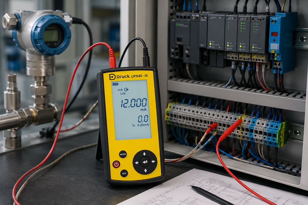
If the 4–20 mA signal of a pressure transmitter fluctuates, the fault is often immediately attributed to the sensor. In practice, however, this is only one of several possible causes. An unstable output signal can be caused by the pressure transmitter itself, but just as often by loose terminals, moisture in the connector, EMC interference, incorrect shielding, excessive load, unstable supply voltage or real pressure pulsations in the process.
Especially in maintenance and control cabinet construction, it is therefore important not only to look at the measured value in the PLC. The decisive factor is whether the 4–20 mA signal is already fluctuating directly at the transmitter or whether it is only being distorted on the way to the control system. Only then can it be determined whether the fault lies in the sensor, the current loop, the wiring or the process.
This article explains how fluctuating 4–20 mA signals on pressure transmitters can be systematically narrowed down, what role supply voltage, load, cable shielding and grounding play, and why a comparison measurement directly at the transmitter and at the PLC input is particularly meaningful.
Table of contents
- Basics: Why pressure transmitters work with 4–20 mA
- Typical symptoms of an unstable 4–20 mA signal
- Sensor fault or current loop problem?
- Checking the supply voltage
- Correctly evaluating load and voltage reserve
- Checking wiring, terminals and connectors
- Moisture in the connector and at the cable connection
- EMC, cable shielding and grounding
- Process pulsation instead of signal error
- Using filter and damping functions correctly
- Comparison measurement directly at the transmitter and at the PLC input
- Table: Symptom, possible cause and useful check
- Practical example: Pressure signal fluctuates only during pump operation
- Which measuring instruments / products are suitable?
- Conclusion: Check the current loop first, then replace the sensor
- FAQ: Frequently asked questions about fluctuating 4–20 mA signals
Basics: Why pressure transmitters work with 4–20 mA
The 4–20 mA signal is widely used in industrial measurement technology because it is robust, easy to transmit over longer cables and simple to monitor. A pressure transmitter converts the measured pressure into a current value. Typically, 4 mA corresponds to the start of the measuring range and 20 mA to the end of the measuring range.
Example: A pressure transmitter with a measuring range of 0 to 10 bar delivers approximately 4 mA at 0 bar, approximately 12 mA at 5 bar and approximately 20 mA at 10 bar. The PLC or a display unit converts this current value back into a pressure value.
The advantage of the current loop is that the current is the same throughout the entire loop circuit. If 12.00 mA is measured directly at the transmitter, the same current should also arrive at the PLC input if the wiring is intact. This exact principle helps with troubleshooting.
However, it is important to note: A 4–20 mA signal is only stable if supply voltage, load, wiring, shielding, connection quality and process conditions are suitable for the application. A fluctuating PLC value therefore does not automatically mean that the pressure transmitter is defective.
Typical symptoms of an unstable 4–20 mA signal
An unstable pressure signal can appear in different ways. The measured value suddenly jumps by a few percent, drifts slowly, jitters within a range of a few tenths of a bar or shows short outliers. In other cases, the signal only becomes unstable during the operation of certain machines, for example when a motor, frequency inverter or pump is switched on.
In the PLC, a pressure value is often visible that fluctuates slightly all the time, even though the process should actually be stable. Sometimes limit value messages also occur even though the actual pressure is not critical. In control loops, a fluctuating signal can cause valves, pumps or controllers to operate unsteadily.
Another typical symptom is a difference between the local display and the PLC value. If a pressure transmitter with an on-site display shows a stable pressure, but the PLC displays a jumping signal, wiring, interference or the input card are likely suspects.
Conversely, an apparent electrical problem may actually come from the process. Pulsating pumps, fast valve switching, cavitation, air bubbles, pressure shocks or mechanical vibrations can generate real pressure fluctuations that the pressure transmitter correctly detects.
Sensor fault or current loop problem?
The most important question during troubleshooting is: Is the current really already fluctuating at the pressure transmitter, or does the fluctuation only occur on the way to the control system? Without this distinction, the sensor is often replaced unnecessarily even though the fault is in the cable, connector or PLC input.
A useful first step is to measure the 4–20 mA signal as close to the transmitter as possible. If the current is stable there but fluctuates in the PLC, this indicates a problem in the wiring, shielding concept, input card or signal evaluation. If the current already fluctuates directly at the transmitter, it must be checked further whether the sensor itself is unstable or whether the process pressure is actually fluctuating.
A second measurement at the PLC terminal is particularly helpful. If the current values directly at the transmitter and at the PLC input match, the current loop is probably not the cause. If the values differ or the fluctuations only occur at one point, the fault location is narrowed down significantly.
For such checks, a suitable current loop calibrator is very helpful because it can measure and simulate 4–20 mA signals and, in some cases, also provide loop power. This allows the system to be tested much more specifically than only using a display in the control system.
Checking the supply voltage
A 2-wire pressure transmitter requires sufficient supply voltage in order to operate correctly and drive the required loop current. If the voltage is too low or breaks down under load, the output signal can become unstable.
The supply voltage should not only be measured under no-load conditions, but under real operating conditions. The decisive factor is the voltage that actually still arrives at the transmitter. Long cables, high loads, additional display instruments, isolation amplifiers or input modules can cause voltage losses.
Typical indications of a problematic supply are signal interruptions, a measured value that only fluctuates in certain ranges, unexplained jumps at higher current values or an output signal that does not cleanly reach the upper measuring range.
In practice, it should therefore be checked whether the power supply, loop voltage, terminals, cable length and all devices connected in series match the required minimum supply voltage of the pressure transmitter. The manufacturer’s sensor specifications must be observed.
Correctly evaluating load and voltage reserve
The load is the electrical resistance against which the pressure transmitter must drive its current signal. This includes, for example, the input resistance of the PLC, display instruments, isolation amplifiers, additional resistors, cable resistances and connection points.
If the load is too high, the available voltage may no longer be sufficient to drive 20 mA cleanly. The signal may then be limited, distorted or unstable. This is particularly critical with long cables, several devices connected in series or a supply voltage that is too low.
A typical error occurs when an additional display or isolation amplifier is later inserted into the loop without reassessing the total load. The system then appears to function normally at low pressure values, but shows jumps or limitations at higher currents.
For a clean evaluation, supply voltage, minimum operating voltage of the transmitter, maximum loop current and total load must be considered together. If the voltage reserve is too small, the loop should be adjusted accordingly.
Checking wiring, terminals and connectors
Many unstable 4–20 mA signals are caused by simple contact problems. Loose terminals, damaged conductors, crushed cables, poor crimp contacts, oxidized plug connections or mechanically stressed cables can cause brief interruptions or changes in resistance.
Such faults are often difficult to find because they do not occur permanently. A control cabinet may appear inconspicuous during standstill, while vibrations, machine movements or temperature changes during operation cause contact problems.
Connections directly at the pressure transmitter are particularly critical. Moisture, temperature, vibration, mechanical stress and the process environment often act together there. A connector that appears to be correctly seated externally may still have corrosion, moisture or poor contact inside.
During inspection, terminals, connectors, cable glands, strain relief, shield connection and cable routing should be checked. Work on electrical systems and control cabinets may only be carried out by qualified personnel.
Moisture in the connector and at the cable connection
Moisture is a common cause of fluctuating or drifting signals. It can enter through leaking connectors, damaged cable glands, incorrectly installed seals or condensation. Cleaning processes, splash water or high humidity can also stress the connection area.
Moisture in the connector does not always lead to a complete failure. Often, leakage currents, transition resistances or intermittent contact problems occur. The signal then appears unstable, drifts slowly or reacts sensitively to temperature and humidity changes.
It is typical for the fault to occur more strongly after cleaning, after standstill, during a cold system start or at high humidity. When the connector is opened, corrosion, traces of moisture or discolored contacts are sometimes visible.
To prevent this, suitable protection rating, correctly installed cable glands, suitable seals, clean connector installation and appropriate cable routing are important. Cables should be routed so that water does not run directly toward the connector.
EMC, cable shielding and grounding
Electromagnetic interference can affect 4–20 mA signals, especially when signal cables are routed parallel to motor cables, frequency inverter cables, contactor cables or high-power loads. Unclear grounding concepts or incorrectly connected shields can also cause problems.
Although current signals are more robust than many voltage signals, they are not completely immune. Interference can appear as short peaks, noise, jumps or periodic fluctuations. It often occurs only when a specific drive is running or a contactor switches.
The cable shielding must match the system. In many applications, a cleanly connected shield on one defined side or according to the system concept is required. The decisive factor is that no unwanted compensating currents flow through the shield and that interference is not coupled into the measuring cable.
If EMC is suspected, it should be checked whether signal cables are routed separately from power cables, whether shield connections are properly implemented, whether the control cabinet design is EMC-compliant and whether frequency inverters, motor cables and grounding are correctly installed.
Process pulsation instead of signal error
Not every fluctuation is an electrical fault. Especially in pressure measurement, real pressure pulsations often occur. Piston pumps, dosing pumps, fast-switching valves, compressors, hydraulic power units or cavitation can cause the process pressure to fluctuate strongly.
A pressure transmitter with a fast response time displays these fluctuations correctly. In the PLC, this then appears like an unstable signal, even though the sensor is only showing the actual process. This is particularly relevant when the measuring point is located directly downstream of a pump, upstream of a valve or on an unfavorable pipe section.
Whether process pulsation is present can be checked by comparing with a reference measuring instrument, measuring at a quieter measuring point or analyzing the timing. If the fluctuation always occurs synchronously with the pump cycle, valve switching or machine cycle, this strongly indicates real pressure dynamics.
In such cases, the sensor should not simply be replaced. It is more useful to evaluate the measuring point, damping, process connection, pipe routing and control strategy. Depending on the application, damping or averaging may be useful, as long as safety-relevant pressure peaks are not hidden.
Using filter and damping functions correctly
Many pressure transmitters or PLC inputs offer a damping or filter function. This can be used to smooth fast fluctuations. This can be useful if the process is actually pulsating and the application requires a stable average value.
However, damping must not be used to simply “filter away” unexplained faults. If loose terminals, moisture, EMC or an unstable supply are the cause, the fault must be corrected. A filter function can visually calm the symptom, but it does not eliminate the cause.
Damping must also be selected appropriately for process pulsations. Excessive damping can cause real pressure peaks, fast pressure rises or critical limit violations to be detected too late.
In practice, it should first be clarified whether the fluctuation is electrical or process-related. Only then should it be decided whether damping in the transmitter, in the PLC or in the visualization is useful.
Comparison measurement directly at the transmitter and at the PLC input
The comparison measurement is one of the most important steps when dealing with fluctuating 4–20 mA signals. The goal is to compare the current value at different points in the loop. This makes it possible to narrow down whether the fault occurs directly at the transmitter or only along the signal path.
If a stable current is measured directly at the transmitter, but a fluctuating value arrives at the PLC input, the fault is likely in the cable, terminals, shielding, input card or interference. If the current already fluctuates directly at the transmitter, it must be checked whether the process pressure is actually fluctuating or whether the transmitter is operating unstably.
A current loop calibrator can also simulate a defined 4–20 mA signal. If the PLC is tested with a stable simulated signal and still shows fluctuations, the fault is more likely on the input card, parameterization or signal processing side. If the PLC shows stable values with a simulated signal, the transmitter or process becomes the focus again.
This procedure prevents unnecessary sensor replacement. It shows whether the fault originates in the measuring instrument, the wiring or the process dynamics.
Table: Symptom, possible cause and useful check
| Symptom | Possible cause | Useful check |
|---|---|---|
| Signal fluctuates directly at the transmitter | Real pressure pulsation, sensor problem, unstable supply | Compare process pressure, measure supply, perform reference measurement |
| Signal is stable at the transmitter, but unstable at the PLC | Wiring, EMC, input card, shielding or terminal problem | Compare current value at both measuring points, check cable and PLC input |
| Signal jumps when a motor is switched on | EMC coupling, incorrect cable routing or grounding problem | Check cable routes, shielding, grounding and frequency inverter environment |
| Signal drifts slowly | Moisture in the connector, temperature change, process change | Check connector, dry connection, compare process conditions |
| Signal does not reach 20 mA cleanly | Load too high or supply voltage too low | Calculate loop voltage, load and voltage reserve |
| Measured value constantly jitters slightly | Process pulsation, noise, sampling too fast or missing damping | Reference measurement, filter setting and measuring point check |
| Signal drops out briefly | Loose terminal, cable break, connector problem or supply dip | Check terminals, connectors, cables and power supply under operating conditions |
| PLC shows wrong pressure with stable mA value | Incorrect scaling or parameterization | Check 4 mA and 20 mA values, measuring range and unit in the PLC |
| Fluctuation occurs only during pump operation | Real pressure pulsation or mechanical vibration | Check correlation with pump cycle, evaluate measuring point and damping |
Practical example: Pressure signal fluctuates only during pump operation
In a system, the control system repeatedly reports fluctuating pressure values. The pressure transmitter is connected to a PLC as a 2-wire device with a 4–20 mA output. During standstill, the system shows stable values. As soon as the pump runs, however, the displayed pressure value jumps significantly.
Initially, it is suspected that the pressure transmitter is defective. Before replacement, however, the current signal is measured directly at the transmitter. There, the current fluctuates in the same rhythm as the PLC value. A reference measuring instrument is then connected to a nearby measuring point. Pressure pulsations are also visible there.
This makes it clear: The fluctuation is not caused by the PLC and not by a cable fault, but by real pressure pulsations in the process. The pump generates periodic pressure shocks that the transmitter correctly detects.
In the next step, it is checked whether the measuring point is suitable for the control task. In addition, moderate damping is used in the evaluation so that the process value is displayed more steadily. At the same time, care is taken to ensure that relevant pressure peaks continue to be detected. In this case, the pressure transmitter did not need to be replaced.
Which measuring instruments / products are suitable?
If 4–20 mA signals on pressure transmitters need to be checked, a current loop calibrator is significantly more helpful than a simple visual check in the PLC. The Druck UPS4E current loop calibrator is particularly suitable. It is suitable for measuring and sourcing current signals and helps to systematically check current loops directly on site.
The UPS4E is particularly practical when it is necessary to clarify whether a 4–20 mA signal is stable directly at the transmitter, whether the same current arrives at the PLC input or whether the control system responds correctly to a simulated signal. This allows sensor, cable and input card to be separated from each other much more quickly.
For troubleshooting pressure transmitters, the ability to source a defined mA signal is particularly valuable. This allows the PLC to be checked independently of the real process. If the PLC displays correct values with a stable injected signal, the scaling and input card are probably correct. If it still jumps, further troubleshooting must be carried out on the PLC side or in the wiring.
In addition, a suitable digital multimeter can be helpful for voltage checks, supply checks and continuity tests. However, for the actual diagnosis of the 4–20 mA current loop, a dedicated current loop calibrator such as the UPS4E is the more practical solution because it supports measurement, simulation and loop testing in one device.
If it is also necessary to check whether the fluctuation really comes from the process, a reference pressure measuring instrument or digital test pressure gauge can be useful. This makes it possible to compare whether the pressure is actually pulsating mechanically or whether only the electrical output signal is unstable.
Conclusion: Check the current loop first, then replace the sensor
A fluctuating 4–20 mA signal on a pressure transmitter can have many possible causes. In addition to an actual sensor defect, supply voltage, load, loose terminals, moisture, EMC, shielding, grounding, PLC parameterization and real process pulsations are the main possible causes.
The most important measure is clean fault isolation. If the signal is measured directly at the transmitter and additionally at the PLC input, it can quickly be identified whether the fault originates in the sensor, the cable or the control system. With a current loop calibrator, a defined signal can also be simulated in order to check the input card and scaling.
For practical work, this means: Do not replace the pressure transmitter prematurely. First check the current loop, supply, load, wiring, EMC and process conditions. This avoids unnecessary downtime and identifies the actual cause much faster.
FAQ: Frequently asked questions about fluctuating 4–20 mA signals
Why does the 4–20 mA signal of my pressure transmitter fluctuate?
Causes can include unstable process pressure, loose terminals, moisture in the connector, EMC interference, incorrect shielding, excessive load, insufficient supply voltage or a sensor problem.
Is a fluctuating signal always a defective pressure transmitter?
No. Very often the cause lies in the wiring, current loop, supply, PLC evaluation or in the process itself. The transmitter should only be replaced after systematic testing.
How do I check whether the fault is at the transmitter or in the cable?
The 4–20 mA signal should be compared directly at the transmitter and at the PLC input. If it is stable directly at the transmitter but unstable at the PLC, the fault is probably in the signal path.
What role does the supply voltage play?
A supply voltage that is too low or unstable can prevent the transmitter from driving the loop current cleanly. The voltage should therefore be checked under real operating conditions.
What does load mean in a 4–20 mA loop?
The load is the electrical resistance in the current loop. This includes the PLC input, display instruments, isolation amplifiers, cable resistances and additional resistors. If the load is too high, the signal can become unstable.
Can EMC influence a 4–20 mA signal?
Yes. Especially with unfavorable cable routing next to motor cables, frequency inverters or contactors, interference can be coupled in. Shielding, grounding and cable routing should be checked.
How can moisture in the connector be recognized?
Indications include drifting or jumping values, corrosion, discolored contacts, faults after cleaning or stronger problems at high humidity. The connector should be professionally checked and sealed.
Can the process itself make the signal fluctuate?
Yes. Pumps, valves, hydraulic power units, compressors or cavitation can generate real pressure pulsations. The transmitter then measures correctly, but the process pressure is actually unstable.
What does a damping function do?
Damping smooths fast fluctuations. It can be useful for process pulsations, but should not be used to hide unresolved electrical faults.
Why should measurement be performed directly at the transmitter?
The measurement directly at the transmitter shows whether the current is already fluctuating at the source. This makes it easier to distinguish whether the sensor, process or signal path is the cause.
Why also measure at the PLC input?
The comparison with the PLC input shows whether the signal is changed on the way through the cable, terminals, shielding or input card.
How can a current loop calibrator help?
A current loop calibrator can measure and simulate mA signals. This makes it possible to check whether transmitter, cable, PLC input and scaling are working correctly.
Which device is suitable for testing 4–20 mA loops?
The Druck UPS4E current loop calibrator is suitable for testing 4–20 mA current loops. It supports on-site troubleshooting when current signals need to be measured or simulated.
What does it mean to simulate an mA signal?
When simulating, the calibrator outputs a defined current value, for example 4 mA, 12 mA or 20 mA. This can be used to check whether the PLC recognizes and scales the value correctly.
When should the pressure transmitter be replaced?
Replacement is useful if supply, load, wiring, PLC input, EMC and process conditions have been checked and the signal directly at the transmitter remains implausible or unstable.