


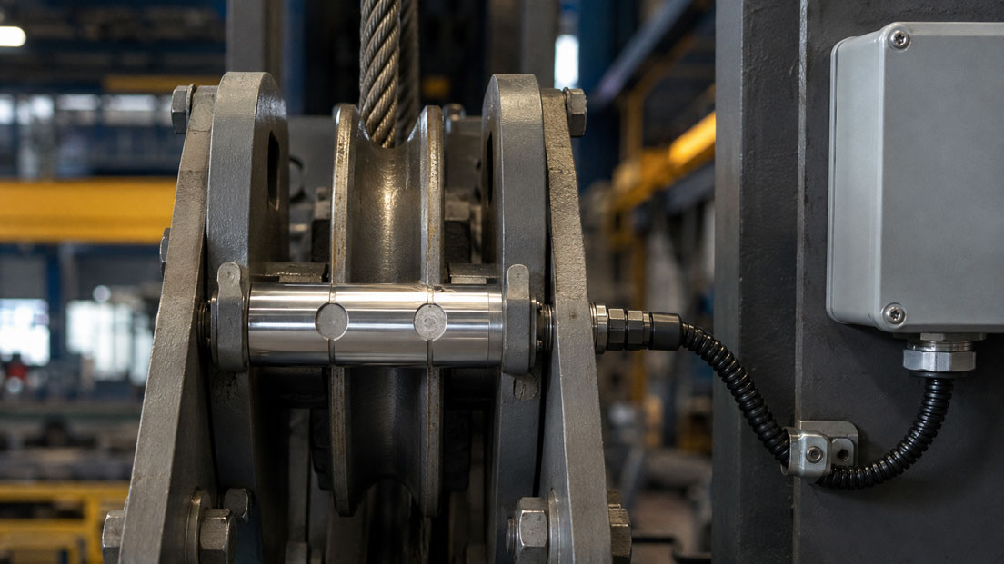
Load pins, force-measuring pins or instrumented load bolts enable direct force measurement at bearing points, sheaves, cable winches and articulated joints in cranes and hoists. They replace a conventional pin and measure the mechanical load directly within the force path. This often allows load measurement to be integrated into an existing design without additional tensile or compression force transducers.
However, the mechanically simple replacement of a pin must not obscure the fact that a load pin only provides reliable values under defined installation conditions. Bearing width, force introduction, shear planes, alignment, axial retention and anti-rotation protection all influence the signal. Even minor mechanical stress, off-centre loading or additional transverse forces can cause measurement errors and permanently overload the measuring body.
In cranes, the force acting on a sheave does not automatically correspond to the suspended load. Rope tension, reeving, deflection angle, efficiency, dead weight and dynamic loads must all be considered. The rated force of the load pin must therefore not be derived solely from the crane’s maximum payload.
Suitable force transducers and evaluation instruments can be found in the ICS category Force Sensors and Force Measuring Instruments. Additional sensors for position, movement, rotational speed, torque, inclination and vibration are summarised under Displacement, Force and Motion Sensors.
Table of Contents
- What does a load pin measure?
- Determining the force path and actual bearing force
- Correctly designing bearing points and shear planes
- Considering force direction and installation position
- Planning anti-rotation protection and axial retention
- Avoiding transverse forces, bending moments and force shunts
- Defining the measuring range and safety margin
- Assessing dynamic loads and signal filtering
- Protecting the cable outlet and electrical connection
- Distinguishing redundancy from a safety function
- Calibration in the installed condition
- Systematic selection and installation procedure
- Typical errors with load pins
- Practical example: Load pin on a sheave
- Which products and solutions are suitable?
- Conclusion
- Frequently asked questions
What does a load pin measure?
A load pin is a force transducer in the form of a pin. The measuring body contains strain gauges or thin-film sensors that detect a very small elastic deformation of the pin. A measuring bridge and, where applicable, an integrated amplifier convert this deformation into an electrical output signal.
Typical output signals include:
- mV/V as a direct strain-gauge bridge signal,
- 4–20 mA,
- 0–10 V,
- digital interfaces such as CANopen,
- two separate output channels in versions designed for this purpose.
The load pin does not automatically measure the payload at the crane hook. It measures the force occurring at its specific bearing point and in its sensitive measuring direction. Depending on the installation, this may be the bearing force of a sheave, the rope force at a fixed point, the joint force in a boom or a resultant force made up of several components.
A mechanical model is therefore required to convert the measured value into a hook load. Rope routing, the number of load-bearing rope falls, deflection angle, friction and dead weight must correspond to the actual design.
Determining the force path and actual bearing force
Before selecting the measuring range, it must be established how the load flows through the structure. A load pin installed in a rope sheave, for example, measures the resultant force produced by the two rope tensions acting on the sheave.
If the rope tension is equal on both sides of the sheave, the resultant bearing force can be approximated as follows:
R = 2 × T × sin(β / 2)
Where:
- R: resultant force acting on the sheave and load pin,
- T: rope tension,
- β: rope deflection angle.
With a complete deflection of 180°, the resultant force is theoretically twice the rope tension. At a smaller deflection angle, the bearing force is correspondingly lower. If the rope geometry changes during crane movement, the relationship between the hook load and the load-pin force can also change.
In a multi-fall hoisting system, the rope tension can be estimated using the following relationship:
T ≈ Fload / (n × η)
Here, n is the number of load-bearing rope falls and η is the overall efficiency of the reeving system. Friction in sheaves and bearings, rope stiffness and uneven load distribution can result in the individual rope falls not being loaded equally.
The dead weight of the hook block, lifting beam, grab and other load-handling attachments also contributes to the mechanical load. If only the net payload is to be displayed, these dead loads must be taken into account during zeroing or in the evaluation system.
Correctly designing bearing points and shear planes
Many load pins are installed in a clevis-type bearing arrangement. Two outer lugs support the pin, while the force is introduced through a central component, such as a sheave or joint lug. This produces two defined shear zones.
The exact position of the sensitive measuring zones depends on the manufacturer and design. The bearing widths, spacing between the lugs and width of the central force-introduction element must therefore match the load-pin drawing. An existing design must not be assessed solely on the basis of the pin diameter.
The following points are particularly important for reproducible loading:
- dimensionally accurate and aligned bearing bores,
- suitable tolerances between the pin and bores,
- a defined position of the central force introduction,
- sufficient clearance between the central component and the outer bearing lugs,
- no frictional connection that bypasses part of the force around the load pin,
- no sharp-edged damage or drilling chips in the bearing points.
If the central component is pressed laterally against one of the bearing lugs, part of the load may be transmitted by friction. This force shunt prevents the load pin from measuring the full bearing force. At the same time, lateral preloading may occur.
Manufacturer specifications for minimum clearances and fits always apply to the specific product series. They must not be transferred to another load pin or bearing design without verification.
Considering force direction and installation position
A load pin is inserted longitudinally into the bearing bores, but the actual operating force generally acts radially on the pin. The sensor system is designed for a defined radial force direction. Depending on the version, this direction is indicated by arrows, a groove, a flat or another marking on the end of the pin.
During installation, the marking must be aligned with the calculated main force direction. Rotation of the pin changes the position of the sensitive measuring direction relative to the actual force vector.
For an idealised case with an angular deviation α:
Fmeasuring direction = F × cos(α)
The component acting perpendicular to the measuring direction is:
Ftransverse = F × sin(α)
The actual measurement deviation cannot be determined completely from these equations because cross-sensitivity, bearing friction and bending deformation also have an effect. The equations nevertheless show that angular misalignment not only changes the useful signal but also generates an unwanted transverse load.
If the force direction changes significantly during operation, it must be checked whether a load pin sensitive in one direction is suitable. With moving booms or changing rope angles, a different measuring point, multi-component measurement or application-specific characteristic-map correction may be required.
Planning anti-rotation protection and axial retention
The load pin must be secured against uncontrolled rotation and axial movement. A pin retainer or positive-locking device is often used for this purpose. However, this securing element has a different function from the load-bearing bearing points.
A suitable pin retainer:
- maintains the defined force direction,
- prevents axial migration,
- is secured using captive fasteners,
- does not transmit any significant axial load during normal operation,
- does not restrict elastic deformation in the load direction.
If the anti-rotation device is clamped too rigidly or pulled against a deformable component, it may itself create a force shunt. The load pin may then respond differently depending on bolt tightening, temperature or deformation of the crane structure.
The groove or flat for the pin retainer often also serves as a reference for the installation position. It must not be modified, reworked or added at an unverified position.
Avoiding transverse forces, bending moments and force shunts
A load pin is designed for a specific type of bearing arrangement and force direction. Additional loads can affect both the measured value and the mechanical service life.
| Additional load | Typical cause | Possible consequence |
|---|---|---|
| Transverse or lateral force | Misaligned rope, non-aligned lugs or side pull | Cross-sensitivity, friction and additional bending |
| Bending moment | Off-centre force introduction or excessive bearing spacing | Zero-point shift, measurement error or plastic deformation |
| Torsion | Rotating sheave, seized bearing or twisted installation | Interference signal and damage to the measuring body |
| Force shunt | Friction contact, additional support or preloaded retaining device | Only part of the actual force is measured |
| Impact load | Load catching, abrupt braking or sudden start-up | Short-term overload and permanent zero-point change |
Worn or stiff bearings are particularly critical. If the sheave does not rotate freely around the load pin or its bearing arrangement, torque may be introduced into the pin. The condition, lubrication and clearance of the bearings must therefore be included in the regular inspection of the complete measuring point.
Defining the measuring range and safety margin
The rated force of the load pin must be greater than the highest actual bearing force that can occur. It is not sufficient to consider only the crane’s static rated load.
The maximum load calculation should include, among other factors:
- maximum payload,
- dead weight of the hook block and load-handling attachments,
- rope routing and deflection angle,
- acceleration during starting and braking,
- taking up slack rope and load catching,
- friction and unequal rope tensions,
- wind and lateral forces,
- side pull and swinging loads,
- manufacturing tolerances and structural deformation,
- possible exceptional operating conditions.
A load pin normally has separate specifications for rated force, service force limit, permissible overload and, where applicable, breaking force. These terms must not be confused. The permissible overload is not a measuring range that can be used continuously and is not a freely available safety margin for normal operation.
A measuring range selected too narrowly may be overloaded by dynamic peaks. An unnecessarily large measuring range, on the other hand, reduces the usable resolution and can make small load changes more difficult to detect.
There is no universal factor that can be used to size every crane load pin safely. Selection must be based on mechanical calculations, the risk assessment, manufacturer data and the requirements applicable to the crane. Structural design remains the responsibility of the crane or machine manufacturer and appropriately qualified specialists.
Assessing dynamic loads and signal filtering
During lifting, lowering, braking and positioning, load changes occur much faster than during static weighing. The measuring chain must capture this dynamic behaviour adequately.
The following factors must be checked:
- mechanical natural frequency of the load pin and bearing arrangement,
- bandwidth of the integrated amplifier,
- sampling rate of the PLC or evaluation electronics,
- filter time and averaging,
- response time of the overload shutdown,
- storage of short-term peak values.
Strong filtering produces a stable weight display but may conceal critical load peaks or delay shutdown. Different signal paths or filter settings may therefore be required for indication, control and safety monitoring.
Recurring oscillations must not be treated merely as an unwanted measurement signal. They may indicate swinging loads, rope vibration, bearing clearance or mechanical resonance.
Protecting the cable outlet and electrical connection
The electrical connection of a load pin is often located at the end face. The cable outlet must therefore be considered during the mechanical design stage. It must not collide with the rope, sheave, retaining plate or adjacent components.
The following points are important for a robust installation:
- sufficient cable bending radius,
- strain relief outside the moving bearing area,
- protective conduit or cable duct against abrasion and stone impact,
- no cable torsion caused by a rotatable load pin,
- a sealed and accessible plug connection,
- shielded measuring cable suitable for the signal,
- physical separation from motor, brake and power cables,
- a clearly defined grounding and shielding strategy.
For mobile cranes, movement paths, boom position, drag chains, vibration, moisture and possible high-pressure cleaning must also be considered. Even an electrically suitable sensor can fail prematurely if the cable routing is unsuitable.
Distinguishing redundancy from a safety function
A load display and a safety-related overload limitation are different tasks. A single sensor signal shown on a display does not automatically constitute a safety function.
A complete overload protection function includes, among other elements:
- a suitable load pin and mechanical integration,
- signal conditioning and diagnostics,
- safety-related logic,
- an output element for limiting or stopping the hazardous movement,
- fault response in the event of cable break, short circuit or an implausible signal,
- validation and regular functional testing.
Redundant electrical output signals can improve diagnostics. However, two channels from the same measuring body do not eliminate all common-cause failures. Mechanical overload, an incorrect force direction, a blocked bearing or common cable damage may affect both channels.
Selected heavy-duty load pins can provide redundant output signals and can be integrated into a suitably certified overload protection system. However, the achieved safety category or Performance Level applies only to the fully evaluated system configuration and not automatically to the individual load pin.
Calibration in the installed condition
Factory calibration tests the load pin under defined conditions. The actual crane bearing arrangement may differ from these conditions. Fits, bearing spacing, friction, force direction and the actual rope path all influence the complete measuring chain.
After mechanical installation, the unloaded zero point should therefore be checked first. A load test with several known load steps is then recommended.
A suitable test procedure includes:
- Record the zero signal with the structure completely unloaded.
- Apply a known test load slowly.
- Check several load steps across the intended working range.
- Compare increasing and decreasing loads.
- Check repeatability after complete unloading.
- Test dynamic load application at reduced speed.
- Check alarm and shutdown points separately.
- Document the measuring setup, rope reeving and environmental conditions.
Depending on the system, the reference load can be provided by verified weights, a suitable reference force measurement or calibrated lifting equipment. The test must reproduce the actual force path. A tensile test at another point on the crane may be unsuitable if it changes the rope angle or mechanical transmission ratio.
After replacing the load pin, sheave, bearing, rope or load-bearing lugs, the measuring point should be checked again. The same applies after a mechanical overload or a noticeable zero-point shift.
Systematic selection and installation procedure
- Define the measurement task: Distinguish between load indication, process control, overload warning and a safety function.
- Select the measuring point: Assess the force path, accessibility, rope geometry and movement.
- Calculate the bearing force: Consider payload, dead weight, reeving, deflection angle and dynamics.
- Record the installation geometry: Document pin diameter, bearing widths, bores, tolerances and force introduction.
- Determine the force direction: Identify the main force and possible lateral force over the complete movement range.
- Select the rated force: Observe operating peaks and manufacturer-specific load limits.
- Define the output signal: Select mV/V, 4–20 mA, 0–10 V, CANopen or redundant channels to suit the evaluation system.
- Plan anti-rotation and axial retention: Design the retaining device without mechanical stress or force shunts.
- Define the cable route: Consider movement, strain relief, protection and EMC.
- Monitor installation: Do not hammer the load pin into place and observe the output signal during installation.
- Calibrate within the system: Check several known load steps and dynamic conditions.
- Define recurring inspections: Regularly check the zero point, plausibility, bearing condition, cable and shutdown function.
Typical errors with load pins
| Error | Possible consequence | Suitable measure |
|---|---|---|
| Rated force selected from the hook load | Actual bearing force is underestimated or overestimated | Calculate rope forces, deflection angle and reeving |
| Force-direction marking not aligned | Measurement deviation and unwanted transverse loading | Align the load pin according to the drawing and marking |
| Load pin installed with a hammer | Mechanical overload and zero-point shift | Check the bores and insert the pin without force |
| Central lug clamps against the clevis | Friction creates a force shunt | Ensure the specified lateral clearance |
| Anti-rotation device clamped too rigidly | Elastic deformation is restricted | Use the pin retainer only as a securing element |
| Rope runs diagonally over the sheave | Lateral force and additional bending moment | Check rope guidance, alignment and sheave bearing |
| Cable routed without strain relief | Plug or cable breakage | Protect the cable mechanically and provide strain relief |
| Strong averaging in the PLC | Dynamic overload is detected too late | Design the indication and protection signals separately |
| Only the zero point is checked | Incorrect sensitivity remains undetected | Perform a multipoint test using known loads |
| Two outputs automatically considered safe redundancy | Common-cause failures remain undetected | Assess and validate the complete safety chain |
Practical example: Load pin on a sheave
A hoist is to measure the load using the bearing pin of a sheave. The maximum total load, including the hook block and load-handling attachments, is 120 kN. The hoisting system has two load-bearing rope falls. For this simplified calculation, an overall efficiency of 0.92 is assumed.
The approximate rope tension is:
T = 120 kN / (2 × 0.92) = 65.2 kN
The rope is deflected through 150° around the monitored sheave. This results in a bearing force of:
R = 2 × 65.2 kN × sin(75°) ≈ 126 kN
The load pin is therefore already loaded with approximately 126 kN at the maximum static load. The force at the measuring point is greater than the total load of 120 kN and considerably greater than the rope tension of 65.2 kN.
For starting, braking and load oscillations, a calculated dynamic peak force of 1.25 × 126 kN is considered in this example:
Rdynamic ≈ 158 kN
A load pin with a measuring range of 100 kN would clearly be unsuitable. A version with a measuring range up to 200 kN could be suitable from a measurement perspective, provided that its specific service force limit, permissible overload, installation geometry and safety requirements cover the application.
During installation, it is found that the existing central sheave mount contacts one side of the clevis. This contact would transfer part of the bearing force through friction. The design is therefore modified so that force introduction remains centred and the specified clearance is maintained.
The load pin is aligned with the resultant rope force using its marking and secured against rotation and axial displacement using an unloaded pin retainer. The connection cable is routed through protective conduit along the crane frame and strain-relieved outside the sheave area.
A test using several known loads is then performed. The zero point, characteristic slope, repeatability and overload warning are checked. Only this test confirms that the calculated bearing force is measured correctly in the actual structure.
Which products and solutions are suitable?
WIKA Models F5301 and F53C1
The WIKA F5301 and F53C1 models are load pins with thin-film technology for measuring ranges from 0–5 kN to 0–200 kN. They are designed for static and dynamic measurement tasks and can replace existing pins in crane systems, hoists, sheaves, cable winches, clevis bearings or rolling bearings.
The corrosion-resistant versions feature an integrated amplifier. Depending on the configuration, active current or voltage signals as well as digital or redundant outputs are available. The exact geometry and signal option must be adapted to the application.
WIKA Models F5308, F53C8 and F53S8
The WIKA F5308, F53C8 and F53S8 models are heavy-duty load pins with measuring ranges starting at 10 kN. They are designed for harsh operating conditions in cranes, hoists, offshore applications and mobile machinery.
Depending on the version, available outputs include 4–20 mA, 0–10 V and CANopen. Redundant output signals are possible. Certain versions can be used as part of a suitably certified WIKA overload protection system. The safety-related suitability must be confirmed for the complete configuration.
WIKA Model F5802
The WIKA F5802 load pin is designed for rated forces from 20 to 10,000 kN. It is particularly suitable for high bearing forces in large crane systems, harbour and offshore cranes, cable winches, sheaves and special-purpose machinery.
In this series too, the load pin replaces an existing non-measuring pin. Reliable selection requires the complete bearing geometry, rated and peak forces, force direction, environmental conditions, output signal and intended safety function.
ICS Schneider Messtechnik supports the selection of a suitable load pin, coordination of the mechanical geometry, signal conditioning, integration into a PLC or crane control system and the planning of calibration and overload monitoring.
Conclusion
A load pin is a space-saving solution for load measurement in cranes and hoists because it can directly replace an existing bearing or connecting pin. However, it does not automatically measure the hook load, but rather the actual force at its installation point.
Force path, rope reeving, deflection angle, bearing widths, shear zones and dynamic loads must all be considered during selection. The measuring direction must correspond to the resultant force. Transverse forces, torsion, off-centre force introduction and force shunts can distort the measured value and damage the load pin.
The anti-rotation device must not restrict the elastic deformation of the measuring body. The cable outlet, axial retention, bearing condition and mechanical movement must also be considered from the outset.
For overload protection and other safety functions, a measured value alone is not sufficient. The sensor, evaluation system, diagnostics, control logic and shutdown element must be assessed as a complete safety chain. Final calibration or load testing in the installed condition is therefore an essential part of commissioning.
Frequently asked questions about load pins in cranes and hoists
What is the difference between a load pin and a force-measuring pin?
The terms are often used synonymously. They refer to a mechanically load-bearing pin with integrated force measurement technology that replaces a conventional bearing or connecting pin.
Does a load pin measure the hook load directly?
Not necessarily. It measures the force at its bearing point. Rope routing, reeving, deflection angle, efficiency and dead weights must be considered when calculating the hook load.
Why does a load pin have a force-direction marking?
The sensor system is designed for a defined radial measuring direction. The marking allows this measuring direction to be aligned correctly with the actual force vector.
May a load pin be hammered into place during installation?
No. Strong impacts can mechanically overload the measuring body and change the zero point. If the pin cannot be installed easily, the bores, alignment, tolerances and possible contamination must be checked.
Why does the load pin require anti-rotation protection?
Rotation changes the alignment of the sensitive measuring direction. The anti-rotation device maintains the defined position and can also prevent axial movement of the pin. However, it must not absorb any additional operating force.
How do transverse forces affect the measurement?
Transverse forces can produce additional bending, friction and cross-sensitivity. They may be caused by side pull, misaligned bearing points or ropes running laterally over the sheave.
How large must the overload margin be?
There is no universal value. Static load, dynamics, rope forces, impact loads, exceptional operating conditions and the load limits of the specific load pin must all be considered. The design must be carried out by qualified specialists in accordance with the machine and safety requirements.
Are two output signals automatically redundant and safe?
Two channels can improve diagnostics and availability. However, they may share common mechanical or electrical failure causes. Suitability for a safety function can only be determined by assessing and validating the complete measuring and shutdown chain.
Must the load pin be calibrated in the installed condition?
Testing in the installed condition is particularly recommended because the bearing arrangement, force direction, friction and rope geometry influence the complete measuring chain. At a minimum, the zero point, several load steps, repeatability and shutdown points should be checked.