


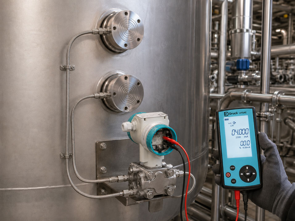
A SITRANS P pressure transmitter with diaphragm seals enables reliable pressure and level measurements on hot, aggressive, viscous, crystallising or hygienically demanding media. The process diaphragm separates the transmitter from the process medium. The pressure is transmitted to the measuring cell through a completely filled capillary or through the fill fluid of the diaphragm seal.
This separation extends the range of possible applications, but it also introduces additional hydrostatic and thermal influences into the measuring chain. If the diaphragm seals and transmitter are installed at different heights, the fluid column inside the capillary generates a constant pressure. In differential-pressure level measurements with two diaphragm seals, the vertical distance between the upper and lower process connections also produces a fixed zero-point shift.
This offset is not a sensor fault. It is part of the physical design of the measuring point and must be considered when defining the lower and upper range values. A simple zero adjustment without prior calculation may produce a plausible value under the current conditions, but it can result in incorrect scaling of the subsequent level indication.
Suitable Siemens products can be found in the ICS category Siemens Pressure Measurement. Additional field instruments and components are summarised under Siemens Process Instrumentation.
Table of Contents
- How does a diaphragm seal transmit the process pressure?
- Direct mounting, remote seal and combined configurations
- How does the hydrostatic height offset occur?
- Correctly calculating a single diaphragm seal with capillary
- Differential-pressure level measurement with two diaphragm seals
- Distinguishing between zero elevation and zero suppression
- Planning capillary length and routing
- Considering temperature gradients and fill fluid
- Why symmetrical capillaries are important
- Safely designing for vacuum and low absolute pressures
- Correctly assessing response time and damping
- Correctly configuring LRV, URV and zero point
- Systematic commissioning of the measuring point
- Typical errors in remote-seal systems
- Practical example: Closed tank with two diaphragm seals
- Which products and solutions are suitable?
- Conclusion
- Frequently asked questions
How does a diaphragm seal transmit the process pressure?
A diaphragm seal essentially consists of a flexible process diaphragm, an internal chamber filled with fill fluid and a connection to the measuring instrument. The process pressure causes a slight deflection of the diaphragm. This volume displacement is transmitted to the transmitter’s measuring cell through the nearly incompressible fill fluid.
With a directly mounted diaphragm seal, the transmitter is located immediately behind the process connection. With a remote seal, a flexible capillary is installed between the diaphragm seal and the transmitter. The diaphragm seal, capillary and measuring cell form a factory-evacuated, filled and matched system.
The capillary is therefore not a conventional impulse line. It must not be opened, shortened, extended or refilled in the field. Even small gas bubbles or losses of fill fluid can significantly affect pressure transmission, the zero point and the response time.
The complete measuring system is influenced by factors including:
- diaphragm diameter and diaphragm stiffness,
- fill fluid and its density, viscosity and thermal expansion,
- capillary length and capillary internal diameter,
- process and ambient temperature,
- vertical position of the diaphragm seal and transmitter,
- measuring span and required dynamic response,
- absolute pressure and possible vacuum conditions.
Direct mounting, remote seal and combined configurations
| Configuration | Advantages | Points to consider |
|---|---|---|
| Directly mounted diaphragm seal | Short pressure-transmission path, small fill volume and fast response | The transmitter is exposed directly to process heat, vibration and a potentially difficult-to-access measuring point |
| Diaphragm seal with capillary | The transmitter can be installed in a cooler, more accessible and lower-vibration location | Hydrostatic height offset, temperature errors and longer response time |
| Two remote seals on a differential-pressure transmitter | Closed tanks can be measured without conventional impulse lines; process gas pressure is compensated | Fixed zero-point shift caused by the vertical distance between the diaphragm seals |
| Directly mounted lower diaphragm seal and upper remote seal | Compact design at the lower connection and only one long capillary | Asymmetrical temperature and height behaviour on the two measuring sides |
Direct mounting is often preferable from a metrological perspective, provided the temperature, vibration and accessibility conditions permit it. A capillary should therefore not be selected longer than technically necessary.
In a differential-pressure measurement with a directly mounted diaphragm seal on one side and a remote seal on the other, the capillary fill column acts on only one measuring side. This arrangement must be calculated particularly carefully because thermal effects do not compensate each other as effectively as they do with two symmetrical capillaries.
How does the hydrostatic height offset occur?
The fill fluid inside the capillary has its own density. A hydrostatic pressure therefore develops between two different elevations:
pH = ρF × g × Δh
Where:
- pH: hydrostatic pressure of the capillary fill fluid,
- ρF: density of the fill fluid,
- g: acceleration due to gravity, approximately 9.81 m/s²,
- Δh: vertical height difference.
Assuming a fill-fluid density of 950 kg/m³, a height difference of only two metres produces a pressure of:
pH = 950 kg/m³ × 9.81 m/s² × 2 m ≈ 18,640 Pa ≈ 186 mbar
A height difference of two metres can therefore generate an offset that is significantly larger than the actual process measuring range in applications with small spans.
The vertical height difference is decisive for the calculation. The actual hose or capillary length may be considerably greater if the line contains loops. A horizontal capillary section does not create an additional static pressure head, but it does increase the fill volume, temperature influence and response time.
Correctly calculating a single diaphragm seal with capillary
For a gauge-pressure or absolute-pressure measurement with a single remote seal, the offset depends on the position of the transmitter relative to the diaphragm seal.
Transmitter below the diaphragm seal
The fluid column acts additionally on the measuring cell. The transmitter detects a positive pressure even if no corresponding process pressure is present at the diaphragm seal itself.
Transmitter above the diaphragm seal
The fluid column acts in the opposite direction. A negative or pressure-reducing component is produced at the transmitter.
The signs must always be defined based on the actual connection arrangement and elevation. Applying a positive or negative correction value without considering the actual geometry can double the error.
If the transmitter is repositioned later, the hydrostatic offset of a system with a single remote seal also changes. The measuring point must therefore be recalculated and checked after every change in installation height.
Differential-pressure level measurement with two diaphragm seals
In a closed vessel, the lower diaphragm seal is normally connected to the high-pressure side and the upper diaphragm seal to the low-pressure side of the differential-pressure transmitter.
The gas or vapour pressure inside the vessel acts on both process connections and is largely cancelled during differential-pressure measurement. The remaining components are:
- the hydrostatic pressure of the process liquid,
- the hydrostatic pressure of the fill fluid in both capillaries,
- possible temperature-related and system-related deviations.
Even when the vessel is empty, the taller fill-fluid column on the low-pressure side generates a differential pressure. The lower range value is therefore often a significantly negative differential pressure.
For an ideally symmetrical system with two equally filled capillaries, the following approximations apply:
Δp0% = −ρF × g × H
Δp100% = ρP × g × H − ρF × g × H
Here, H is the vertical distance between the lower and upper diaphragm seals, ρP is the density of the process medium and ρF is the density of the fill fluid.
The actual measuring span is:
Measuring span = ρP × g × H
The capillary filling therefore mainly shifts the measuring range. With an ideally symmetrical configuration, it does not change the hydrostatic process span.
Distinguishing between zero elevation and zero suppression
During configuration, a distinction must be made between a measuring-range shift and a zero-point correction.
Zero elevation
With zero elevation, the lower range value is below zero. The transmitter may, for example, have to output 4 mA at a differential pressure of −280 mbar. This situation is common with closed tanks equipped with two diaphragm seals.
Zero suppression
With zero suppression, the lower range value is above zero. A positive pressure must be present before the measuring range begins. This can occur, for example, with a transmitter installed at a lower elevation, a constant head or a permanently present liquid column.
Zero-point correction or position correction
A position correction eliminates small zero-point deviations caused by the transmitter’s final installation position. It does not replace the calculation of the capillary height.
The calculated hydrostatic offset must be included in the configuration of the lower and upper range values. It must not be removed indiscriminately by performing an arbitrary zero adjustment.
Planning capillary length and routing
Capillaries should be as short as technically possible and only as long as required for installation, maintenance and thermal decoupling. Unnecessary reserve length reduces the performance of the measuring system.
The following basic principles apply to capillary routing:
- Do not kink, crush or bend capillaries below their permitted bending radius.
- Do not use capillary lines to support the weight of the transmitter.
- Protect the lines mechanically and secure them at regular intervals.
- Avoid direct contact with hot pipelines, steam lines or heat tracing.
- Do not provide unnecessary loops.
- With two capillaries, use equal lengths and comparable routing wherever possible.
- Do not open, shorten or extend capillaries using fittings.
- Observe the factory-defined installation position and permissible bending radius.
A larger capillary internal diameter can improve the hydraulic response, but it also increases the fill volume and therefore often increases the temperature influence. The capillary diameter, length, fill fluid and diaphragm size must therefore be designed as one complete system.
Considering temperature gradients and fill fluid
Fill fluids change their volume with temperature. Because the diaphragm, capillary and measuring cell form a closed system, this volume change produces an additional pressure effect.
The temperature influence increases particularly with:
- long capillary lines,
- large fill volumes,
- large temperature changes,
- different temperatures on the high- and low-pressure sides,
- small measuring spans,
- small or stiff diaphragm-seal membranes.
The fill fluid must not only be suitable for the maximum process temperature. The following factors are also relevant:
- minimum ambient and start-up temperature,
- viscosity at low temperature,
- density and temperature coefficient,
- vapour pressure during vacuum operation,
- physiological requirements for food and pharmaceutical applications,
- compatibility with the process in the unlikely event of diaphragm damage.
The electronic temperature compensation of the SITRANS P can only compensate the specified influences of the transmitter itself. An external, asymmetrical temperature gradient along the capillaries is a characteristic of the complete diaphragm-seal system and must be minimised during the mechanical design stage.
Why symmetrical capillaries are important
With two remote seals, the high- and low-pressure sides should be configured as symmetrically as possible. This includes:
- equal capillary lengths,
- equal capillary internal diameters,
- the same fill fluid,
- the same diaphragm-seal design and diaphragm size,
- comparable mounting and insulation,
- ambient temperatures that are as similar as possible.
Equal capillary lengths alone do not guarantee good temperature compensation. If one capillary is routed next to a hot process pipe while the other is exposed to cooler ambient air, different volume changes occur and produce a differential-pressure error.
Parallel routing can help equalise the temperature conditions. However, the capillaries must not be mounted so close to hot surfaces that both are exposed to impermissibly high temperatures.
A symmetrical design also does not compensate for the intentional height difference between the upper and lower diaphragm seals. This hydrostatic offset remains and must be included in the configuration.
Safely designing for vacuum and low absolute pressures
In vacuum and negative-pressure applications, the displayed gauge pressure is not the only decisive parameter. The actual absolute pressure occurring in the process and inside the diaphragm-seal system is critical.
An unsuitable design can result in:
- outgassing or evaporation of the fill fluid,
- bubble formation inside the pressure-transmission system,
- an unstable or slowly drifting zero point,
- delayed pressure transmission,
- permanent damage to the diaphragm-seal membrane.
For permanently low absolute pressures, a combination of diaphragm seal, fill fluid, capillary and transmitter that is explicitly suitable for vacuum service must be selected. Vacuum conditions during start-up, emptying, cleaning and fault situations must also be considered.
The transmitter installation height can also be relevant in vacuum applications. An unfavourable position can further reduce the local pressure inside the capillary. The permissible installation position must therefore be checked based on the specific Siemens system configuration and must not be transferred indiscriminately from a normal positive-pressure application.
Correctly assessing response time and damping
A remote-seal system responds more slowly hydraulically than a directly mounted transmitter. The delay increases particularly with:
- long capillaries,
- small capillary internal diameters,
- viscous fill fluids,
- low ambient temperatures,
- small diaphragm-seal membranes,
- a large displacement volume required by the measuring cell.
Electronic damping in the transmitter additionally smooths the output signal. However, it cannot recover hydraulic response that has already been lost.
During troubleshooting, the following effects must therefore be distinguished:
| Observation | Possible cause |
|---|---|
| The measured value already responds slowly on the local display | Hydraulic delay caused by the diaphragm seal, capillary or fill fluid |
| The internal measured value responds quickly, but the 4–20 mA output responds slowly | Electronic damping or downstream filtering |
| The response becomes significantly slower at low temperature | Increasing viscosity of the fill fluid |
| The measured value drifts slowly after a temperature change | Thermal stabilisation of the complete remote-seal system |
Correctly configuring LRV, URV and zero point
The lower range value, LRV, and upper range value, URV, are required for configuration.
- LRV: actual differential pressure at 0% level or at the lower end of the measuring range,
- URV: actual differential pressure at 100% level or at the upper end of the measuring range,
- Measuring span: URV minus LRV.
The calculation should be documented before checking the installation. The following information is required:
- vertical distance between the effective diaphragm-seal membranes,
- installation height of the transmitter,
- density of the process liquid,
- density of the fill fluid at the reference temperature,
- assignment of the high- and low-pressure sides,
- open or closed vessel,
- directly mounted or remote diaphragm seal on each measuring side.
A permissible position or zero-point correction is performed only after the measuring range has been configured. The measuring point must be in a clearly defined reference condition during this procedure.
A zero adjustment on a supposedly empty tank is unsuitable if residual liquid, flushing medium, a gas-pressure difference or an unknown density is still present. In that case, the transmitter would accept not only its positional deviation but also an actual process pressure as the new zero point.
Systematic commissioning of the measuring point
- Check the design: Compare the transmitter, diaphragm seals, fill fluid, capillaries and process data with the order.
- Inspect the diaphragms: Check for dents, scratches, contamination and missing protective caps.
- Record the installation heights: Document the centre points of the lower and upper diaphragm-seal membranes and the position of the transmitter.
- Inspect the capillaries: Check their length, mounting, bending radii and thermal environment.
- Assign the high- and low-pressure sides: Compare the connections clearly with the calculation and documentation.
- Calculate LRV and URV: Consider the process-fluid and fill-fluid densities and all relevant elevations.
- Configure the transmitter: Set the unit, lower range value, upper range value and required damping.
- Perform a position correction: Only in a defined reference condition and in the final installation position.
- Check the measuring points: Where possible, check 0, 50 and 100% or several known reference conditions.
- Check the current loop: Compare the 4–20 mA output, PLC scaling and control-system indication.
- Observe the temperature behaviour: Check the measured value again after thermal stabilisation.
- Document the as-built data: Record the elevations, capillary routing, configuration and zero-point correction.
If the transmitter is repositioned later, a capillary is rerouted or the process density changes, the design must be checked again. The original configuration may then no longer be valid.
Typical errors in remote-seal systems
| Error | Possible consequence | Suitable corrective action |
|---|---|---|
| Capillary height not calculated | Constant offset across the complete measuring range | Calculate the hydrostatic pressure of the fill fluid |
| LRV set to 0 mbar | The 4–20 mA scaling does not correspond to the actual measuring point | Use the actual differential pressure at 0% as the LRV |
| Hydrostatic offset removed using zero trim | The lower range value appears correct, but the upper range value is incorrect | Configure the measuring-range shift using LRV and URV |
| Unequal capillary lengths | Different thermal and dynamic behaviour | Use a symmetrical configuration with two remote seals |
| One capillary is routed along a hot pipeline | Temperature-dependent zero-point error | Route and protect both capillaries under comparable conditions |
| Excess capillary length coiled up | Larger fill volume and slower response | Order only the required capillary length |
| Electronic damping set too high | Level changes and alarms are delayed | Assess hydraulic and electronic delay separately |
| Standard fill system used in vacuum service | Outgassing, drift or unstable measurement | Select a diaphragm-seal system suitable for vacuum service |
| Diaphragm-seal membrane cleaned mechanically | Diaphragm deformation and permanent zero-point shift | Use only approved, gentle cleaning methods |
| Transmitter repositioned after commissioning | The height offset is no longer correct | Record the new geometry and check the measuring point again |
Practical example: Closed tank with two diaphragm seals
The level in a closed process vessel is to be measured using a SITRANS P differential-pressure transmitter and two remote seals.
The following values apply to this simplified example:
- distance between the lower and upper diaphragm seals: 3.0 m,
- density of the process medium: 1,100 kg/m³,
- density of the fill fluid: 950 kg/m³,
- lower diaphragm seal connected to the high-pressure side,
- upper diaphragm seal connected to the low-pressure side,
- identical capillaries and identical fill fluid.
Differential pressure at 0% level
At 0% level, there is no hydrostatic process head between the two diaphragm seals. However, the fill-fluid column on the low-pressure side produces a negative offset:
LRV = −950 kg/m³ × 9.81 m/s² × 3.0 m
LRV ≈ −27,959 Pa ≈ −279.6 mbar
Process span
At 100% level, the process liquid produces:
Δpprocess = 1,100 kg/m³ × 9.81 m/s² × 3.0 m
Δpprocess ≈ 32,373 Pa ≈ 323.7 mbar
Differential pressure at 100% level
The upper range value is calculated from the negative capillary offset plus the positive process span:
URV = −279.6 mbar + 323.7 mbar
URV ≈ +44.1 mbar
The SITRANS P is therefore not configured for 0 to 323.7 mbar, but for:
4 mA = −279.6 mbar
20 mA = +44.1 mbar
The measuring span remains 323.7 mbar. The measuring range is merely shifted by the fill-fluid column.
If a zero adjustment were performed with the tank empty and a measuring range of 0 to 323.7 mbar were then configured, the indication might show 0% at the empty point. However, the physical range assignment of the transmitter would not be documented correctly, making subsequent inspections or device replacement unnecessarily difficult.
After configuration, the indicated differential pressure, the 4–20 mA signal and the scaling in the control system are checked. It is also verified that both capillaries are routed comparably and exposed to similar ambient temperatures.
Which products and solutions are suitable?
Siemens SITRANS P320
The SITRANS P320 is a digital process transmitter for gauge pressure, absolute pressure, differential pressure, flow and hydrostatic level measurement. It can be combined with suitable diaphragm seals for difficult media and special process conditions.
HART communication, local configuration and diagnostic functions support the configuration of the measuring range, damping and output signal, as well as checking the measuring point during commissioning.
Siemens SITRANS P420
The SITRANS P420 is suitable for demanding process measuring points with high requirements for accuracy, diagnostics and operational reliability. Here too, the specific combination of measuring cell, diaphragm seal, capillary, diaphragm and fill fluid must be designed for the application.
Siemens diaphragm seals for SITRANS P320/P420
Different diaphragm-seal designs are available for the SITRANS P320/P420 series. These include directly mounted versions and systems with flexible capillaries for gauge-pressure, absolute-pressure and differential-pressure measurements.
When ordering, the process connection, nominal pressure, diaphragm material, coating, fill fluid, capillary length, temperature, vacuum conditions and installation height should be specified in full. The diaphragm seal and transmitter are designed as a matched measuring system.
UPS4E loop calibrator
The UPS4E loop calibrator can be used to check the 4–20 mA signal of the SITRANS P during commissioning, maintenance and troubleshooting.
This allows the transmitter output, wiring, analogue input and scaling in the control system to be checked separately. The electrical loop test complements the mechanical and hydrostatic inspection of the diaphragm-seal system.
ICS Schneider Messtechnik provides support in selecting and designing the SITRANS P320/P420, diaphragm-seal configuration, fill fluid, capillary length, measuring span and materials, as well as in calculating LRV, URV and the hydrostatic zero-point shift.
Conclusion
A SITRANS P with diaphragm seals does not measure only the process pressure. The system also detects the hydrostatic pressure components of the fill fluid inside the capillaries. Different installation heights can therefore produce considerable constant offsets.
With a single remote seal, the offset depends on the position of the transmitter relative to the diaphragm seal. In differential-pressure level measurement with two diaphragm seals, the vertical distance between the upper and lower process connections produces a fixed measuring-range shift.
This shift must be configured using the actual lower and upper range values. An arbitrary zero adjustment does not replace the hydrostatic calculation.
Equal capillary lengths, comparable routing and symmetrical temperature conditions reduce differential errors. However, they compensate neither the height offset nor an incorrect process density.
For a stable measuring point, the transmitter, diaphragm seals, membranes, fill fluid, capillaries, installation height, temperature range, vacuum conditions and required response time must be designed together from the ordering stage.
Frequently asked questions about SITRANS P with diaphragm seals
Why does the SITRANS P indicate a negative differential pressure when the tank is empty?
With two remote seals, the fill-fluid column between the upper and lower diaphragm seals acts even when the tank is empty. The taller column on the low-pressure side often produces a negative differential pressure. This value must be included as the LRV.
Can the height difference simply be removed using a zero adjustment?
A position correction can eliminate small installation-related zero-point deviations. However, the hydrostatic offset of the capillary filling is part of the measuring-range calculation and should be configured using the LRV and URV.
Which height is used for the calculation?
The vertical height difference between the effective reference points is used, normally the centre points of the diaphragm-seal membranes or the distance between the diaphragm seal and the measuring cell. The total installed capillary length is not decisive for the static pressure head.
Do both capillaries have to be the same length?
For differential-pressure measurements with two remote seals, equal capillary lengths are generally recommended. However, identical designs, the same fill fluid and comparable temperature conditions are equally important.
Can excess capillary length be coiled?
A limited reserve length can be routed neatly, but it should be avoided wherever possible. Additional capillary length increases the fill volume, temperature influence and response time.
Why does the zero point drift when the temperature changes?
The fill fluid expands as a function of temperature. If the two capillaries are heated differently or the system has an asymmetrical design, an additional differential pressure is produced.
Can electronic damping compensate for a long capillary?
No. Electronic damping additionally smooths the signal. It cannot reduce the hydraulic delay of a long or cold capillary.
What must be considered in vacuum applications?
The fill fluid, diaphragm seal and installation position must be suitable for the lowest occurring absolute pressure. Otherwise, outgassing, bubble formation, drift or delayed pressure transmission can occur.
Does the transmitter have to be reconfigured after being repositioned?
With a single remote seal or an asymmetrical system, the hydrostatic offset may change. The new geometry must therefore be calculated and the measuring point checked again.
How is the 4–20 mA scaling checked?
After pressure configuration, the transmitter display, loop current, analogue input and control-system value are compared. A loop calibrator can be used to check the electrical signal path independently of the process.