


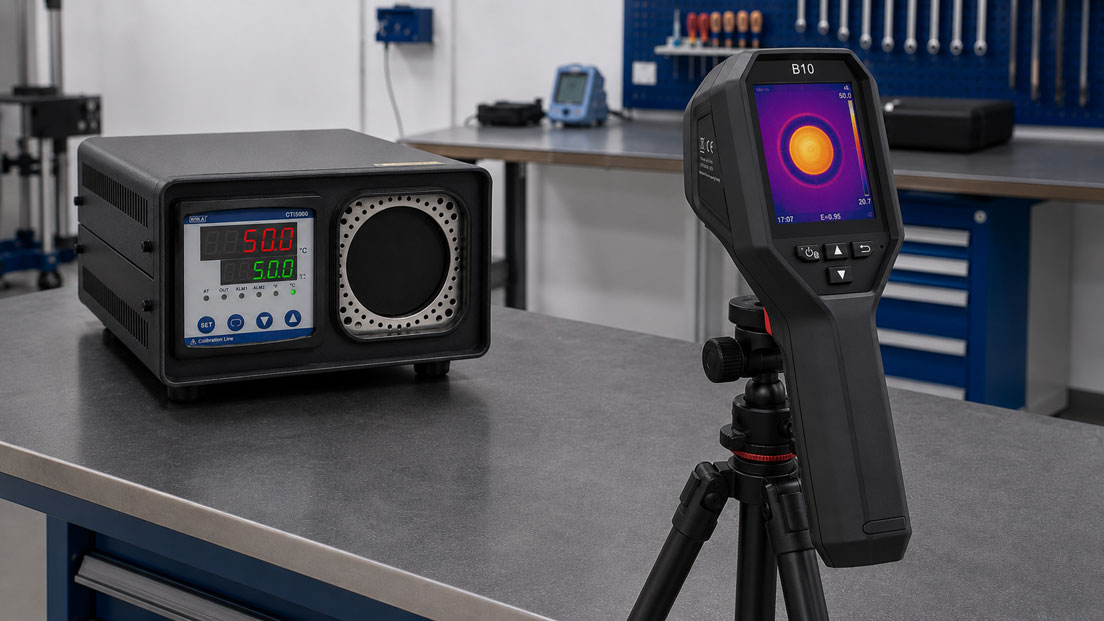
An infrared thermometer is positioned in front of a calibration source whose display shows exactly 200 °C. However, the IR instrument measures only 194 °C. Is the thermometer incorrectly calibrated, or is the test setup simply unsuitable?
With non-contact temperature measurement, knowing only the temperature of the calibration source is not sufficient. The radiation characteristics of the source, the configured emissivity, the size of the source aperture, the measuring spot of the device under test, the measuring distance, optical alignment and thermal stabilisation are equally important.
Errors occur particularly often when the measuring spot of the infrared thermometer is larger than the active radiating surface. The instrument then also detects the cooler surroundings and displays a value that is too low even though the calibration source itself is at the correct temperature.
Suitable devices for generating defined reference temperatures can be found under Temperature Calibrators. Non-contact temperature measuring instruments are grouped under Infrared Temperature Measuring Instruments.
Table of Contents
- Why does IR calibration differ from contact calibration?
- What is a blackbody source?
- Correctly distinguishing between source temperature and reference temperature
- What role does emissivity play?
- Correctly considering measuring spot and distance-to-spot ratio
- Why must the aperture be larger than the measuring spot?
- Selecting the correct measuring distance
- Correctly adjusting focus on pyrometers and thermal imaging cameras
- Considering the optical axis and measuring angle
- Allowing the calibration source to thermally stabilise
- Considering ambient conditions and reflected radiation
- Selecting suitable temperature test points
- Special considerations for thermal imaging cameras
- Distinguishing between IR testing and contact calibration
- Systematic calibration procedure
- Practical example with an IR thermometer
- Typical errors in the calibration setup
- What should be documented?
- Which devices are suitable?
- Conclusion
- Frequently asked questions
Why does IR calibration differ from contact calibration?
With a contact thermometer, the sensor is brought into direct thermal contact with a body of known temperature.
With an infrared thermometer, however, there is no direct contact.
The instrument detects the infrared radiation emitted by the measurement object and calculates a temperature from it.
The measurement result therefore depends not only on the actual surface temperature, but also on:
- the emissivity of the surface,
- reflected ambient radiation,
- the wavelength range of the measuring instrument,
- measuring spot size,
- measuring distance,
- alignment,
- focus,
- temperature distribution within the measuring spot.
A reproducible test therefore requires a defined radiation source.
Blackbody sources or IR calibration sources are used for this purpose.
What is a blackbody source?
An ideal blackbody would completely absorb all electromagnetic radiation incident on it and emit ideally defined thermal radiation corresponding to its temperature.
A real calibration source is designed to approximate this behaviour as closely as possible.
For this purpose, the following are used, for example:
- coated surface sources,
- recesses with a defined surface,
- cavity sources.
A cavity offers an important advantage:
Radiation is reflected multiple times within the cavity. This makes the radiation behaviour more closely approximate that of an ideal blackbody.
For practical calibration, however, it is not decisive whether a device is marketed as a “blackbody”.
What matters are the specified properties of the source being used, such as:
- temperature range,
- emissivity or effective emissivity,
- size of the radiating surface or aperture,
- temperature uniformity,
- stability,
- calibration uncertainty.
Correctly distinguishing between source temperature and reference temperature
A common misconception is:
“The calibrator displays 200.0 °C, so the reference temperature must automatically be exactly 200.0 °C.”
For a traceable calibration, a distinction must be made between:
- the calibrator setpoint,
- the internal temperature indication of the calibrator,
- the calibrated reference temperature of the radiating surface or cavity.
The controller of the calibrator may, for example, be set to 200 °C while the actual calibrated radiation temperature differs slightly from this value.
For a traceable calibration, the calibration value associated with the particular device or its documented correction should therefore be taken into account.
The measurement uncertainty of the reference source must also be included in the subsequent assessment of the device under test.
What role does emissivity play?
In simplified terms, emissivity describes how strongly a real surface emits thermal radiation compared with an ideal blackbody.
For real surfaces:
ε < 1
.
The lower the emissivity, the more strongly reflected ambient radiation can influence the measurement result.
With an IR calibration source, the surface is deliberately designed to achieve a high and defined effective emissivity.
The IR thermometer must be configured accordingly for the calibration source being used.
In many test setups, the device under test is therefore set to the emissivity specified by the manufacturer of the source.
An important error would be, for example:
- the calibration source has a high-emissivity reference surface,
- the IR thermometer is still set to ε = 0.60 from a previous measurement on metal.
The resulting difference can be considerable even though both the source and the thermometer are technically functioning correctly.
Correctly considering measuring spot and distance-to-spot ratio
An infrared thermometer does not measure only a mathematical point.
It detects an area.
The size of this area depends on the optics and the measuring distance.
For many instruments, this is specified as a ratio, for example:
D:S = 50:1
In simplified terms, this means:
At a distance of 500 mm, the characteristic measuring spot is approximately 10 mm.
At a distance of 1,000 mm, it would accordingly be approximately 20 mm.
The greater the distance, the larger the detected measuring area normally becomes.
For calibration, a short distance is therefore not only practical but often necessary from a metrological point of view.
At the same time, however, the minimum distance or focus geometry specified by the manufacturer must be observed.
Why must the aperture be larger than the measuring spot?
The active radiating surface of the calibrator should completely fill the area detected by the infrared thermometer.
If the measuring spot is larger than the aperture, the sensor additionally detects:
- the calibrator housing,
- the surroundings,
- background surfaces.
These areas normally have a different temperature from the actual reference surface.
A typical fault condition is:
- source: 300 °C,
- ambient temperature: 23 °C,
- measuring spot partially outside the aperture.
The IR thermometer then integrates radiation from areas at different temperatures.
The indicated temperature is often lower than the actual source temperature.
Another particularly important point is:
The spot size stated in data sheets does not always mean that 100 percent of the received radiation originates exactly from within this circle.
In practice, there should therefore be sufficient geometric margin between the measuring spot and the radiating surface.
Selecting the correct measuring distance
For a reproducible setup, the measuring distance should be deliberately defined and then kept unchanged between the individual test points.
A suitable distance must fulfil several requirements at the same time:
- the measuring spot must be completely within the reference surface,
- the correct focus distance must be maintained,
- no unnecessarily large proportion of the surroundings should be within the field of view,
- the IR thermometer must not be thermally overloaded.
Particularly with high-temperature sources, a handheld thermometer must not be positioned arbitrarily close to the hot opening.
The permissible ambient temperature specified by the manufacturer of the device under test must be observed.
The source opening itself can be several hundred degrees Celsius and can additionally heat the housing of the IR thermometer through thermal radiation.
A very short distance is therefore not automatically the best distance.
Correctly adjusting focus on pyrometers and thermal imaging cameras
Some infrared thermometers have fixed-focus optics.
Other pyrometers and almost all professional thermal imaging cameras, however, have adjustable focus.
An out-of-focus image or an out-of-focus representation of the reference surface can influence the temperature measurement.
For a thermal imaging camera, the following procedure should therefore be used:
- Ensure that the radiating surface is fully visible.
- Define the measuring distance.
- Focus the camera accurately.
- Only then evaluate the temperature.
Correct focusing is particularly important with small calibration openings.
Considering the optical axis and measuring angle
The infrared thermometer should be aligned as perpendicular as possible to the reference surface or along the intended optical axis of the calibration source.
Large oblique measuring angles can:
- reduce the effective visible area,
- shift part of the measuring spot outside the aperture,
- change reflection effects.
With a cavity source, the device under test should preferably be aimed centrally into the cavity.
For recurring calibrations, a simple mechanical fixture is therefore often preferable to holding the IR thermometer freely by hand.
It improves:
- distance,
- angle,
- centring,
- reproducibility.
Allowing the calibration source to thermally stabilise
Reaching the setpoint for the first time does not automatically mean that the calibration source is already fully stabilised.
After a temperature change, the following components, among others, must thermally stabilise:
- heating element,
- reference sensor,
- radiating surface or cavity,
- surrounding components.
Measuring too early can therefore result in the device under test detecting a value while the radiation source is still changing.
A suitable procedure is:
- Set the target temperature.
- Wait until the setpoint has been reached.
- Allow additional stabilisation time according to the device specification.
- Observe the reference value.
- Record readings only once the condition is sufficiently stable.
Considering ambient conditions and reflected radiation
Even a good calibration source is not located in a completely radiation-free environment.
The surroundings may contain:
- warm machinery,
- heaters,
- windows,
- direct sunlight,
- cold walls,
- other hot calibrators.
With a high-emissivity blackbody source, the influence of reflected ambient radiation is considerably lower than with shiny metallic surfaces.
Nevertheless, the calibration area should have ambient conditions that are as stable as possible.
The following should particularly be avoided:
- direct sunlight on the source or device under test,
- strong air currents,
- rapid changes in room temperature,
- hot external surfaces immediately next to the reference opening.
Selecting suitable temperature test points
A calibration should meaningfully cover the range in which the instrument is actually used.
For an IR thermometer that is mainly used between 50 and 400 °C, for example, a test performed only at room temperature provides little useful information.
Several points across the operating range are appropriate.
For example:
- lower relevant operating point,
- middle operating point,
- upper relevant operating point.
Additional test points may be used where higher accuracy requirements apply.
It is important to allow every temperature point to stabilise completely.
Rapidly moving through several setpoints without sufficient waiting time can create an apparently large instrument deviation that is actually caused by an insufficiently stabilised source.
Special considerations for thermal imaging cameras
With a thermal imaging camera, spatial image evaluation must also be taken into account.
The reference surface should cover a sufficient number of detector pixels.
If only a very small source aperture is viewed from a large distance, the result can be influenced by:
- mixed pixels,
- edge areas,
- out-of-focus imaging,
- surrounding cooler surfaces.
A defined measurement region should therefore be selected within the homogeneous reference surface.
The measurement region must not extend directly to the edge of the calibration surface.
In addition, the following may need to be considered:
- emissivity setting,
- reflected temperature,
- measuring distance,
- atmospheric parameters,
- external optics or protective windows.
Distinguishing between IR testing and contact calibration
An IR thermometer cannot be meaningfully tested simply by placing a contact probe next to its optics.
The two instruments detect different physical quantities.
| Contact Measurement | IR Measurement |
|---|---|
| Sensor is in thermal contact with the measurement object | Sensor receives thermal radiation |
| Heat conduction is decisive | Emissivity and radiation geometry are decisive |
| Immersion depth or thermal contact is relevant | Measuring spot, distance and focus are relevant |
| Temperature bath or dry-block calibrator can be used | IR or blackbody source is required |
A normal dry-block calibrator is therefore not automatically a suitable IR reference.
Non-contact temperature measuring instruments require a defined radiating surface or a suitable IR calibration source.
Systematic calibration procedure
- Identify the device under test: Document device type, serial number, measuring range and optics.
- Check the optical specification: Determine the distance-to-spot ratio or focus distance.
- Select the calibration source: Temperature range and aperture must be suitable for the device under test.
- Check emissivity: Set the device under test to the specified reference value.
- Define the measuring distance: The measuring spot must lie completely within the active radiating surface.
- Align the device under test: Aim centrally and as perpendicular as possible at the reference surface.
- Adjust focus: For focusable instruments, bring the reference surface sharply into focus.
- Set the first test point: Bring the calibrator to the required target temperature.
- Allow stabilisation: Measure only after thermal stability has been achieved.
- Document the reference temperature: Take the calibration value or correction of the source into account.
- Record the DUT value: Record several stable readings.
- Move to additional test points: Keep the geometry unchanged wherever possible.
- Calculate the deviation: Compare the DUT value with the reference value.
- Assess measurement uncertainty: Consider reference, geometry and repeatability.
- Document the results: Clearly record the setup and settings.
Practical example with an IR thermometer
An infrared thermometer with optics of:
50:1
is to be tested at 200 °C.
The IR calibration source being used has a usable reference surface with a diameter of 40 mm.
The technician initially positions the instrument approximately 1.5 m from the source.
The approximate ratio gives:
1,500 mm / 50 = 30 mm measuring spot
At first glance, the 40-mm reference surface appears to be sufficient.
However, the actual optical detection area has almost no margin to the edge of the radiating surface.
The thermometer indicates:
196.2 °C
at a reference temperature of:
200.0 °C
The measuring distance is then reduced while taking the permissible instrument geometry into account.
At 500 mm, the approximate characteristic measuring spot is:
500 mm / 50 = 10 mm
The reference surface now fills the field of view with a clear margin.
After realignment and stabilisation, the instrument indicates:
199.4 °C
The original deviation was therefore not eliminated by adjustment.
The main cause was the unsuitable measuring geometry.
This example shows why an IR thermometer should not simply be aimed at a hot calibration source from an arbitrary distance.
Typical errors in the calibration setup
| Error | Possible Consequence | Suitable Corrective Action |
|---|---|---|
| Only the source setpoint is used | Reference deviation is not taken into account | Use the calibrated reference value or correction |
| Incorrect emissivity configured on the DUT | Systematic temperature deviation | Match emissivity to the reference source |
| Measuring spot larger than the radiating surface | Cooler surroundings are also measured | Reduce the distance or use a larger reference surface |
| No geometric margin to the aperture | Edge areas influence the measured value | Make the measuring spot significantly smaller than the reference surface |
| DUT aligned at an angle | Part of the field of view lies outside the reference surface | Align centrally and as perpendicular as possible |
| Thermal imaging camera not focused | Mixed pixels and inaccurate temperature evaluation | Focus accurately before measuring |
| Measurement taken immediately after changing the setpoint | Source has not yet thermally stabilised | Allow sufficient stabilisation time |
| Handheld instrument positioned directly in front of a very hot opening | Housing and detector are thermally influenced | Observe the permissible measuring distance and ambient temperature |
| Direct sunlight | Additional radiation influences the setup | Perform the calibration under controlled conditions |
| Geometry changed between test points | Poorer comparability | Keep the DUT in a fixed position wherever possible |
What should be documented?
For a reproducible IR calibration, at least the following should be recorded:
- manufacturer and type of the device under test,
- serial number,
- measuring range,
- optics or D:S ratio,
- calibration source used,
- serial number of the reference instrument,
- emissivity of the reference source,
- emissivity setting of the device under test,
- aperture or size of the radiating surface,
- measuring distance,
- alignment,
- focus setting where relevant,
- ambient temperature,
- test points,
- reference temperatures,
- indicated DUT values,
- deviations,
- measurement uncertainty.
For thermal imaging cameras, the measurement region or ROI used should also be documented.
The measurement geometry is therefore part of the calibration conditions and should not be regarded merely as secondary information.
Which devices are suitable?
IR calibration sources and temperature calibrators
Under Temperature Calibrators, various calibration solutions for industrial temperature measuring instruments are available.
For infrared thermometers and thermal imaging cameras, a version with a suitable radiating reference surface or IR insert must be used.
Important selection criteria include:
- temperature range,
- size of the radiating surface,
- effective emissivity,
- stability,
- uniformity,
- calibration uncertainty.
Infrared thermometers
Under Infrared Temperature Measuring Instruments, you will find non-contact temperature measuring instruments for a wide range of industrial applications.
Important selection criteria include:
- temperature range,
- optical resolution,
- focus,
- adjustable emissivity,
- response time,
- measurement accuracy.
Thermal imaging cameras
Thermal imaging cameras require a sufficiently large and homogeneous radiating surface for reliable testing.
Particularly with higher-resolution cameras, the measurement surface should cover enough pixels and remain completely within the homogeneous area.
During calibration, focus, measuring distance, emissivity and reflected temperature should be documented just as carefully as the reference temperature.
ICS Schneider Messtechnik provides support in selecting suitable temperature calibrators, IR thermometers and thermal imaging cameras as well as in designing reproducible test setups for non-contact temperature measurements.
Conclusion
Calibrating an infrared thermometer does not simply mean pointing the instrument at a hot source and comparing two temperature indications.
A defined radiation source with known characteristics is essential.
The emissivity configured on the device under test must match the reference source being used.
The measurement geometry is equally important. The entire relevant measuring spot must lie within the homogeneous radiating surface. An excessive measuring distance can cause the IR thermometer to additionally detect the cooler surroundings.
For focusable pyrometers and thermal imaging cameras, the focus must also be adjusted accurately.
After every significant change in setpoint, the calibration source requires sufficient time to thermally stabilise.
Ambient influences should not be underestimated either. Direct sunlight, hot surrounding surfaces, air currents or significant heating of the device under test by the source can change the result.
For a reproducible calibration, temperature, emissivity, measuring distance, aperture, alignment and focus should therefore all be documented together.
Only then can a measured deviation be reliably attributed to the infrared thermometer rather than to an unsuitable test setup.
Frequently asked questions about calibrating infrared thermometers
Can I calibrate an IR thermometer with a normal dry-block calibrator?
Not directly. A non-contact temperature measuring instrument requires a suitable radiating reference surface or corresponding IR insert.
What is a blackbody source?
It is a radiation source whose behaviour approximates that of an ideal blackbody as closely as possible and whose radiation temperature is used for testing IR measuring instruments.
What emissivity should I set on the IR thermometer?
The setting must match the calibration source being used and the requirements of the calibration procedure. The specifications of the source are decisive.
Why does my IR thermometer read too low at the calibrator?
A common cause is an excessively large measuring spot. If the instrument also detects the cooler surroundings outside the source opening, the indicated temperature decreases.
How large may the measuring spot be?
The relevant measuring spot should lie completely within the homogeneous active reference surface and should have sufficient distance from the edge.
What does 50:1 mean on an IR thermometer?
It describes the ratio between measuring distance and characteristic measuring spot size. In simplified terms, at a distance of 500 mm and a ratio of 50:1, the measuring spot is approximately 10 mm.
Should I position the thermometer as close to the source as possible?
Not arbitrarily close. Measuring spot, focus distance, permissible ambient temperature and thermal radiation from the calibrator must all be taken into account.
Why does the calibration source need to stabilise?
After reaching the setpoint, the radiating surface, reference sensor and other components may still undergo thermal changes. A reproducible reference measurement is possible only after stabilisation.
Does a thermal imaging camera need to be focused?
Yes. An out-of-focus image of the reference surface can lead to mixed pixels and additional measurement deviations, particularly with small source apertures.
Can I use only one test point?
For a meaningful assessment, several test points should normally be used across the temperature range actually used in practice.
Why is the aperture of the blackbody source important?
It determines the size of the defined reference surface visible to the device under test. If it is smaller than the area detected by the IR instrument, the surroundings will also be included in the measurement.
What should be included in an IR calibration report?
In addition to reference and DUT temperatures, the report should particularly document emissivity, measuring distance, aperture, alignment, focus, ambient temperature and the reference source used.