


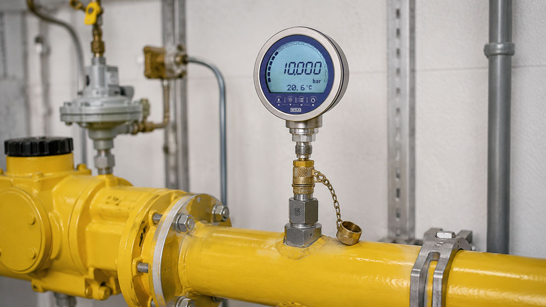
The pressure on a gas line is to be checked regularly for maintenance and commissioning purposes. Mechanically, an existing MINIMESS coupling would fit – but may a standard hydraulic version simply be used for natural gas?
Especially with gases, the mechanical compatibility of a measuring coupling is not sufficient. Materials, seals, gas tightness, operating pressure and approvals must match the specific application. It must also be taken into account that the connected measuring hose contains a dead volume that is filled with gas during coupling and must be safely depressurised again after the measurement.
Special MINIMESS gas versions are available for such applications. One example is the original MINIMESS 1215 gas filling valve with DVGW approval from Hydrotechnik. It provides a defined system access point for pressure measurement and gas sampling and is mechanically opened when the appropriate connection side is screwed on.
Suitable components can be found under MINIMESS DVGW Gas Couplings and Gas Hoses. Further measuring couplings, adapters and hoses are grouped under MINIMESS Couplings and Hoses.
Table of Contents
- How does a MINIMESS gas measuring point work?
- What does DVGW mean for a gas coupling?
- Why not simply use a hydraulic coupling?
- Correctly matching gas and seal material
- Distinguishing operating pressure from system regulations
- Selecting the correct measuring hose
- Considering the hose dead volume
- When is purging required?
- Safe coupling under pressure
- Safely considering residual pressure in the measuring hose
- Checking the leak tightness of the measuring point
- What is the purpose of the protective cap?
- Connecting the measuring instrument correctly
- Special considerations for hydrogen
- Practical example at a gas pressure regulating station
- Typical errors
- What should be documented?
- Which MINIMESS components are suitable?
- Conclusion
- Frequently asked questions
How does a MINIMESS gas measuring point work?
A MINIMESS gas filling valve or corresponding gas coupling is essentially a mechanically actuated check valve.
When uncoupled, the system access point remains closed.
When the appropriate connecting coupling or measuring hose is attached, the valve is mechanically opened. The system pressure then reaches the connected measuring hose and the measuring instrument.
After uncoupling, the valve closes again.
This creates a compact permanent test connection to which, if required, the following can be connected:
- pressure gauges,
- digital pressure gauges,
- pressure sensors,
- pressure calibrators,
- data loggers,
- analysis or sampling systems.
With gases, the complete temporary measuring path must be considered:
Gas line → gas coupling → measuring hose → adapter → measuring instrument
Each of these components is part of the pressure- and gas-carrying measuring point.
What does DVGW mean for a gas coupling?
With a DVGW version, it is not simply the connection thread that is intended for gas.
The specific design has the corresponding approval or certification for the intended field of application.
Hydrotechnik, for example, offers the MINIMESS 1215 gas filling valve with DVGW approval as a system access point for gas pressure systems.
It is intended for connecting control measuring instruments for pressure measurement and gas sampling.
However, it is important to note:
The DVGW designation must not be interpreted as universal approval for every gas and every gas installation.
Different technical rules apply depending on the system.
Examples include:
- gas pressure regulating stations,
- gas metering stations,
- industrial gas supplies,
- building installations,
- liquefied petroleum gas systems,
- hydrogen systems,
- technical gas test benches.
Before selection, it must therefore be clarified which rules and regulations apply to the specific system.
Why not simply use a hydraulic coupling?
Standard hydraulic measuring couplings can look very similar to a gas coupling.
However, this does not mean that both versions are technically identical.
For a gas application, the following must be assessed, among other things:
- gas tightness of the valve,
- permeation through seals and hoses,
- media compatibility,
- temperature range,
- approval,
- ageing behaviour of the seals.
A component that is reliably leak-tight with hydraulic oil does not automatically provide the same level of tightness with gas.
Liquids and gases place different demands on small gaps and elastomer seals.
An existing standard MINIMESS coupling should therefore not be used for a gas line solely because the coupling thread fits.
Correctly matching gas and seal material
Media compatibility does not concern only the metallic components.
The elastomer seals are particularly important.
Depending on the version, the following may be used, for example:
- NBR,
- FKM,
- EPDM,
- other application-specific materials.
The appropriate material depends on the respective gas and the temperature.
The question should therefore not be:
“Is NBR gas-tight?”
but rather:
“Is this specific coupling with this specific seal approved for my gas, my pressure and my temperature?”
For other media, the resistance of the O-rings and surfaces must be checked separately.
This applies in particular to:
- hydrogen,
- aggressive process gases,
- gas mixtures,
- high or very low temperatures.
Distinguishing operating pressure from system regulations
An important distinction must be made between:
- the technically permissible operating pressure of a component,
- the permissible pressure of the complete measuring chain,
- the scope of application of the relevant regulations.
The MINIMESS 1215 gas filling valve with DVGW approval, for example, is available in a version for a maximum operating pressure of 250 bar.
This does not automatically mean that every system designed in accordance with a particular DVGW code of practice may be operated up to 250 bar.
The maximum permissible pressure of the measuring point is always determined by the weakest component.
The following must therefore be considered:
- gas coupling,
- measuring hose,
- hose fittings,
- adapters,
- pressure gauge or pressure sensor,
- any shut-off or relief valves.
The complete setup must be designed for the maximum possible system pressure.
Selecting the correct measuring hose
The measuring hose is just as important as the coupling itself in a gas measuring point.
An arbitrary hydraulic measuring hose should not be used without verification.
The following in particular must be checked:
- approval for the gas,
- hose material,
- inner lining material,
- pressure rating,
- temperature range,
- gas permeability or permeation,
- connection fittings,
- hose length.
For a simple pressure check, a suitable hose that is as short as practical is often advantageous.
A long hose increases:
- dead volume,
- gas quantity in the temporary measuring circuit,
- pressure equalisation time,
- the amount of gas that must be safely depressurised after the measurement.
At the same time, the hose should be long enough to allow the measuring instrument to be positioned safely without hanging mechanically from the pipework.
Considering the hose dead volume
Before connection, the measuring hose normally contains ambient air or the gas from its previous condition.
When the coupling is connected, the process gas fills this additional volume.
In a large gas line, the amount of gas required for a simple pressure measurement is often negligible.
However, with very small closed volumes or sensitive test benches, the additional hose volume can influence the pressure being measured.
Dead volume becomes particularly critical with:
- small test items,
- isolated measuring chambers,
- very low pressures,
- gas analyses,
- sampling.
For reproducible tests, the length and internal volume of the measuring hose should therefore remain as constant as possible.
When is purging required?
Pressure measurement and gas sampling must not be confused at this point.
Pure pressure measurement
For a purely static pressure measurement, it is not generally necessary from a metrological point of view to purge the entire measuring hose with process gas.
After coupling, the system pressure equalises in the hose and at the pressure measuring instrument.
Unnecessary purging would only release additional gas.
Gas sample or gas analysis
The situation is different for gas sampling.
If the actual gas composition is to be determined, the existing dead volume of the hose must be taken into account.
Otherwise, air in the hose or a previously present gas would distort the sample.
In this case, purging is carried out according to the procedure defined for the system until a representative sample is obtained.
The escaping gas must not be discharged uncontrolled into an enclosed working area.
The type and duration of purging as well as safe discharge depend on:
- gas type,
- system,
- explosion protection,
- risk assessment,
- operator instructions.
Safe coupling under pressure
With MINIMESS gas filling valves designed for this purpose, the connecting side can be coupled while the system is pressurised.
However, this does not mean that arbitrary connection work may be carried out under gas pressure.
Before coupling, at least the following should be checked:
- correct coupling series,
- matching mating coupling,
- permissible system pressure,
- gas approval of the hose,
- measuring range of the measuring instrument,
- condition of the thread and sealing surface.
The measuring hose should not be twisted or installed under tensile load.
The coupling should be aligned axially and connected cleanly.
Connecting it at an angle can:
- damage the thread,
- stress the seals,
- result in incomplete valve opening.
The specific coupling sequence must comply with the manufacturer’s instructions and the operating instructions of the system.
Safely considering residual pressure in the measuring hose
After a pressure measurement, gas remains under pressure in the measuring hose.
This point is often underestimated.
Even after the gas coupling on the process side has closed again, compressed gas may still remain trapped in the hose volume.
The measuring circuit must therefore not simply be opened at an arbitrary threaded connection.
Suitable measuring equipment should include a controlled means of depressurisation or should be depressurised according to the procedure specified for the system.
Only then should further connections in the measuring system be loosened.
Especially at high pressures, even the small volume of a measuring hose can contain a relevant amount of stored gas energy.
Checking the leak tightness of the measuring point
Leak tightness should not be checked only when gas odour or a significant pressure loss becomes apparent.
After a new installation or work on a measuring point, leak tightness should be verified according to the test procedure defined for the system.
Possible leakage points include:
- the screw-in thread of the gas filling valve,
- valve seat,
- O-ring,
- coupling connection,
- hose fittings,
- adapters,
- measuring instrument connection.
Particularly with repeatedly used measuring hoses, the following should be checked before use:
- cracks,
- kinks,
- abrasion,
- damaged fittings,
- contaminated sealing surfaces.
With a permanently installed coupling, it should also be checked whether contamination could prevent the check valve from closing completely.
What is the purpose of the protective cap?
A protective cap primarily prevents dirt, dust and mechanical damage from affecting the coupling side.
It should be refitted after the measurement.
However, the protective cap should not be regarded as a substitute for the actual check valve or shut-off element.
The gas tightness of the measuring point must already be ensured by the pressure-bearing and sealing components intended for this purpose.
A missing or damaged protective cap can nevertheless cause long-term problems because contamination can later:
- damage sealing surfaces,
- make coupling more difficult,
- impair valve functions
.
Connecting the measuring instrument correctly
In addition to coupling and hose, the actual measuring instrument must also be suitable for the gas application.
The following must be checked:
- measuring range,
- permissible overpressure,
- gas compatibility of the wetted parts,
- process connection,
- accuracy requirement,
- Ex suitability where applicable.
For a gas line with an operating pressure of, for example, 20 bar, a 0-to-10-bar pressure gauge is unsuitable even if the hose itself is rated up to 250 bar.
Conversely, an excessively large measuring range is also disadvantageous if the required readability or accuracy is lost.
For low connection pressures in heating or gas consumer systems, a low-pressure measuring instrument may therefore be required, whereas gas pressure regulating stations may require completely different measuring ranges.
Special considerations for hydrogen
A coupling suitable for natural gas should not automatically be regarded as approved for pure hydrogen.
Due to its physical properties, hydrogen places particular demands on:
- leak tightness,
- permeation,
- seal materials,
- metallic materials,
- the complete measuring chain.
For hydrogen or hydrogen-rich gases, the specific manufacturer’s approval of the coupling, hose and measuring instrument must therefore be checked.
A general DVGW marking or approval for another gas is not sufficient on its own.
Practical example at a gas pressure regulating station
At a gas pressure regulating station, the outlet pressure is to be checked regularly with a calibrated digital pressure gauge.
For this purpose, a MINIMESS 1215 gas filling valve with the appropriate DVGW version is installed on the pipe.
The technician uses a short measuring hose specified for the application.
Before the measurement, the following are checked:
- coupling series,
- condition of the test point,
- condition of the hose,
- measuring range of the digital pressure gauge,
- permissible operating pressure of all components.
The digital pressure gauge is connected according to the specified measuring setup and the measuring hose is cleanly connected to the test point.
After pressure equalisation, the measured value is documented.
Since only pressure is being measured, the system is not unnecessarily purged to atmosphere.
After completion of the measurement, the coupling is closed or disconnected according to the specified procedure.
The gas remaining in the hose is handled in a controlled manner using the intended depressurisation method.
Finally, the test point and sealing surface are checked and the protective cap is refitted.
A later gas sampling procedure would be handled differently using the same setup:
In that case, the hose dead volume would have to be taken into account and sufficiently purged with process gas according to the procedure defined for the system before a representative sample is taken.
Typical errors
| Error | Possible Consequence | Suitable Corrective Action |
|---|---|---|
| Standard hydraulic coupling used for gas | Media compatibility and gas tightness not verified | Use a version specified for gas |
| DVGW interpreted as universal gas approval | Component used outside its intended application | Check the specific certificate, data sheet and system regulations |
| Only the coupling checked, but not the hose | Weakest component in the measuring chain is unsuitable | Specify the complete gas path |
| Very long measuring hose used | Large dead volume and more trapped gas | Keep the hose as short as practically possible |
| Unnecessary purging performed for every pressure measurement | Unnecessary gas emissions | Purge only as required by the measurement task and procedure |
| Gas sample taken without sufficient consideration of dead volume | Sample distorted by residual gas or air | Purge the measuring path according to the defined procedure |
| Hose opened while still pressurised after measurement | Uncontrolled gas release | Depressurise residual pressure in a controlled manner |
| Measuring instrument with insufficient pressure range | Overload or damage | Consider the maximum possible pressure |
| Damaged protective cap ignored | Contamination and later sealing problems | Maintain and refit the protective cap |
| Hydrogen suitability inferred from natural gas approval | Unsuitable materials or increased permeation possible | Confirm H2 suitability separately |
What should be documented?
For permanently installed gas measuring points, the following information is useful:
- measuring point designation,
- gas or gas composition,
- MINIMESS series,
- part number,
- DVGW approval where required,
- process connection,
- seal material,
- permissible operating pressure,
- permissible temperature range,
- measuring hose used,
- hose length,
- measuring instrument,
- measuring range of the instrument,
- inspection or calibration interval,
- depressurisation procedure,
- purging procedure for gas sampling,
- result of the leak test.
This also helps prevent an optically similar but unsuitable standard component from being installed later during replacement.
Which MINIMESS components are suitable?
MINIMESS 1215 gas filling valve with DVGW approval
The original MINIMESS 1215 gas filling valve from Hydrotechnik is available as a compact system access point for gas-carrying systems.
The corresponding DVGW version is intended, among other things, for pressure measurement and gas sampling.
Features of the specific standard version include:
- mechanically actuated check valve,
- connection side can be coupled under system pressure,
- M10 × 1 process thread in the corresponding version,
- NBR seal,
- metal protective cap,
- maximum operating pressure up to 250 bar,
- operating temperature −20 to +70 °C.
For the specific order, medium, pressure, temperature and connection version must be checked.
Suitable MINIMESS gas hoses
The measuring hose should be selected as part of the gas measuring system.
The following are decisive:
- matching MINIMESS coupling side,
- gas-suitable hose material,
- pressure range,
- temperature range,
- suitable connection to the measuring instrument.
For recurring service work, a predefined measuring hose with a fixed connection to the digital pressure gauge used can reduce the risk of incorrect combinations.
MINIMESS complete systems
Under MINIMESS DVGW Gas Couplings and Gas Hoses, the measuring point, hose and connection can be configured according to the application.
Further hydraulic and pneumatic MINIMESS versions can be found under MINIMESS Couplings and Hoses.
ICS Schneider Messtechnik provides support in selecting the coupling series, seal material, hose, measuring instrument and connection adapters for permanent and mobile gas measuring points.
Conclusion
A gas measuring point with MINIMESS should not simply be assembled from components that can be mechanically screwed together.
For gas applications, coupling, hose, adapter and measuring instrument must be considered as a complete measuring chain.
For suitable applications, the MINIMESS 1215 gas filling valve with DVGW approval provides a compact system access point for pressure measurement and gas sampling.
However, the approval does not replace verification of the specific medium and the regulations applicable to the system.
Selecting the measuring hose is particularly important. It must be suitable for gas, pressure and temperature and should not be unnecessarily long.
Dead volume is particularly relevant with small test volumes and gas samples.
For a simple pressure measurement, routine purging of the hose is not automatically necessary. For gas analysis, however, the dead volume must be taken into account so that a representative sample is obtained.
After the measurement, the residual pressure trapped in the hose must also not be forgotten. The gas must be depressurised in a controlled manner according to the procedure specified for the system.
A technically correct gas measuring point therefore consists of a suitable gas coupling, a matching gas measuring hose, a correctly sized measuring instrument and a defined procedure for coupling, testing, depressurising and documenting.
Frequently asked questions about MINIMESS DVGW gas measuring points
Can I use a standard MINIMESS hydraulic coupling for natural gas?
Not solely on the basis of mechanical compatibility. Media compatibility, gas tightness, seals and any required approvals must be confirmed for the specific version.
What is the MINIMESS 1215 DVGW gas filling valve?
It is a mechanically actuated check valve that provides a compact access point to a gas-carrying system for applications such as pressure measurement or gas sampling.
Can the MINIMESS gas coupling be connected under pressure?
With Hydrotechnik gas filling valves designed for this purpose, the connection side can be coupled while the system is under pressure. The permissible operating conditions and specified procedure must be observed.
Is a DVGW coupling automatically suitable for every gas?
No. DVGW approval, media approval and the respective system regulations must be considered separately.
Does the measuring hose also need to be suitable for gas?
Yes. The hose is a pressure- and media-carrying part of the measuring system and must be suitable with regard to gas, pressure, temperature and connections.
Must the hose be purged before every pressure measurement?
Not generally. For a simple pressure measurement, complete purging is normally not necessary from a metrological point of view. For gas analysis or sampling, however, the dead volume must be taken into account.
Why is dead volume important?
Before connection, the hose contains a certain volume of gas. In small test volumes, filling this volume can influence the pressure; in a gas sample, residual gas can also distort the composition.
What happens to the gas in the hose after uncoupling?
Depending on the setup, gas may remain trapped under pressure in the measuring hose. It must be depressurised in a controlled manner according to the specified procedure.
Is the protective cap a second pressure-bearing seal?
It primarily protects the coupling against contamination and damage. The actual gas tightness must be ensured by the valve and sealing elements intended for this purpose.
Can I use the DVGW version for hydrogen?
Natural gas approval or a general gas approval should not automatically be transferred to pure hydrogen. Materials, seals, permeation and the specific manufacturer’s approval must be checked separately.
How long should the measuring hose be?
As long as necessary for safe positioning of the measuring instrument, but not unnecessarily long. A longer hose increases dead volume and the amount of gas trapped after the measurement.
What must be considered when selecting the pressure gauge?
Measuring range, overload resistance, wetted materials, process connection and, where applicable, Ex suitability must match the gas application.