


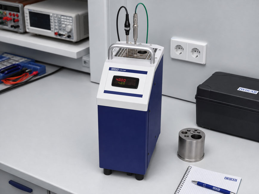
A dry-block calibrator can control temperature very stably and still produce an incorrect calibration result. In such cases, the cause is often not the calibrator itself, but the thermal coupling between the calibration block and the temperature sensor.
Particularly critical factors include:
- an excessively large bore in the calibration insert,
- the resulting air gap,
- insufficient immersion depth,
- different insertion depths of the device under test and reference sensor,
- axial and radial temperature gradients in the block,
- heat conduction through the sensor stem, connection head or cable.
The problem becomes increasingly important as accuracy requirements increase. While an unfavorable setup may hardly be noticeable during a simple functional check, the same setup can already become the dominant source of error in a calibration aiming for a measurement uncertainty of only a few tenths of a kelvin.
The decisive factor is therefore not only which temperature the dry-block calibrator displays, but which temperature the actual sensing element of the device under test really reaches.
Further solutions can be found under calibration equipment at ICS Schneider as well as under our temperature calibrators.
Table of Contents
- How does a dry-block calibrator work?
- What is the purpose of the calibration insert?
- Why is a large air gap problematic?
- How large should the insert bore be?
- Why is immersion depth so important?
- Understanding heat conduction through the sensor stem
- What does axial uniformity mean?
- What does radial uniformity mean?
- Positioning an external reference sensor correctly
- Where is the sensing element located inside the device under test?
- Selecting the correct stabilization time
- Calibrating several sensors simultaneously
- Short temperature sensors as a special case
- Distinguishing thin and thick sensors
- Special considerations for thermocouples
- Special considerations for Pt100s and resistance thermometers
- Material and condition of the calibration insert
- Checking immersion depth with a withdrawal test
- Why the block display is not automatically the DUT temperature
- Influence on measurement uncertainty
- Practical example: Pt100 in an oversized calibration bore
- Dry block or liquid bath?
- Typical fault patterns
- Recommended procedure for dry-block calibration
- Suitable calibration equipment from ICS Schneider
- Conclusion
- FAQ
How does a dry-block calibrator work?
A dry-block calibrator generates a defined temperature in a heated or heated-and-cooled metal block.
A replaceable calibration insert is fitted into this block.
The insert contains one or more bores into which:
- temperature sensors,
- thermometers,
- thermocouples,
- resistance thermometers,
- temperature switches
are inserted.
In simplified terms, the heat path is therefore
heating element → calibration block → calibration insert → device under test → sensing element
Each of these transitions can create a temperature difference.
The temperature display of the calibrator therefore initially indicates the temperature detected by the instrument’s internal reference or control system.
It does not automatically mean:
The sensing element of the device under test has exactly the same temperature.
How closely the two temperatures agree depends significantly on the setup, immersion depth and thermal coupling.
What is the purpose of the calibration insert?
The calibration insert – also frequently referred to as:
- insert,
- insert sleeve,
- adapter insert,
- transition sleeve
– provides the thermal interface between the temperature-controlled block and the device under test.
Ideally, it achieves two objectives at the same time
The sensor should:
be easy to insert and remove
.
At the same time:
the air gap between the sensor and the bore should be as small as possible
.
A bore that is too tight is also problematic
The sensor must not be:
- pressed in,
- jammed at an angle,
- forced into the bore.
Temperature sensors may have small diameter tolerances, slight deformation or surface irregularities.
The insert therefore requires defined clearance.
Why is a large air gap problematic?
Compared with still air, metals have significantly higher thermal conductivity.
If a temperature sensor fits closely inside a suitable metal insert, heat can be transferred relatively well between:
calibration block ↔ insert ↔ sensor
.
With a significantly oversized bore
a larger layer of air surrounds the sensor.
Heat transfer becomes poorer.
As a result, the device under test responds more slowly
and may not yet have fully stabilized at the target temperature even though the block temperature appears stable.
The influence of the environment also increases
The sensor is thermally connected at the same time to:
- the calibration block,
- the ambient air,
- the connection head,
- the connection cable.
The poorer the coupling to the block, the more strongly these additional heat flows can influence the sensing element.
A large air gap therefore does not merely increase waiting time. It can cause a systematic temperature deviation.
How large should the insert bore be?
As a general rule, the bore should match the actual outside diameter of the device under test as closely as possible.
Example
A temperature sensor has an outside diameter of:
6.0 mm
.
A bore of, for example:
12 mm
would be thermally very unfavorable.
The insert should be much closer to the actual sensor diameter.
Observe the manufacturer’s specifications
The required clearance depends on the calibrator, insert system and device under test being used.
For certain calibration systems, for example, bores are used that are only a few tenths of a millimeter larger than the device under test.
For accurate calibration, a suitable single bore or a multi-hole insert manufactured specifically for the sensor diameters being used should therefore be selected wherever possible.
Why is immersion depth so important?
Even a perfectly fitting insert cannot fully compensate for a poor calibration setup if the device under test is not inserted deeply enough.
The sensing element requires a sufficiently long temperature-controlled section
Part of the sensor is located inside the hot or cold block.
The upper part, however, remains at ambient temperature.
This creates axial heat flow along the sensor.
Example
Block temperature:
300 °C
Ambient temperature:
23 °C
.
The temperature difference between the two regions is therefore:
277 K
.
The metallic sensor stem can conduct heat out of the block toward the surroundings.
If the sensing element is located too close to the upper edge of the block, its temperature may therefore be lower than the local block temperature.
At temperatures below ambient
the direction reverses.
Heat then enters the cold calibration zone from the surroundings through the stem.
In both cases, this produces what is known as:
Stem Conduction Error
or heat conduction error through the sensor stem.
Understanding heat conduction through the sensor stem
Heat conduction along the sensor depends, among other things, on:
- material of the protection tube,
- sensor diameter,
- wall thickness,
- sensor length,
- design of the measuring insert,
- temperature difference to the environment,
- immersion depth.
A solid sensor
can conduct more heat along its longitudinal axis than a very thin sensor with a small metallic cross-section.
Connection heads also play a role
Short industrial resistance thermometers often have a relatively large metal connection head located directly above the calibrator.
This can act as an additional heat sink or source of heat input.
This is particularly critical when the actual measuring insert extends only a few centimeters into the block.
What does axial uniformity mean?
The temperature inside a dry block is not exactly the same at every vertical position.
This is referred to as the:
axial temperature distribution
.
The lower section of the block
is usually particularly well temperature-controlled by design.
Toward the upper opening, however, the influence of the surroundings increases.
This can create an axial temperature gradient.
In practice, this means
Two identical sensors can indicate different temperatures if:
Sensor A
has its sensing element positioned deep in the block and:
Sensor B
has its sensing element positioned significantly higher.
Although both are inserted into the same calibrator, their sensing elements are not necessarily located at the same temperature level.
For comparison calibrations, the sensitive measuring elements of the device under test and reference should therefore be positioned at approximately the same axial height.
What does radial uniformity mean?
In addition to vertical temperature distribution, temperature differences can also exist across the cross-section of the block.
This is known as:
radial uniformity
.
With a multi-hole insert
a sensor may, for example, be located:
- close to the center of the block,
- further toward the outside.
The temperatures at these positions may differ slightly.
For high accuracy requirements
the following should therefore be considered:
- reference and device under test should be positioned as close together as possible,
- the bores used should remain defined,
- the same configuration should be used for repeat measurements.
Positioning an external reference sensor correctly
An external reference sensor can measure the actual temperature directly in the vicinity of the device under test.
This is particularly useful for demanding comparison calibrations.
However, positioning is important
The reference sensor should not simply be placed anywhere in the block.
Its sensitive measuring element should preferably be:
at the same height as the sensing element of the device under test
.
Why?
With an axial gradient, for example, the following could occur:
Reference = 200.00 °C
and:
DUT position = 200.35 °C
.
The difference would then incorrectly be attributed entirely to the device under test.
In reality, part of it is caused by the different positions within the block.
Where is the sensing element located inside the device under test?
The outer tip of a temperature sensor is not automatically the location of the actual sensing element.
In a resistance thermometer
the Pt100 may, for example, be located several millimeters or centimeters behind the sensor tip.
In a thermocouple
the location depends on the design of the measuring junction.
For accurate calibration, it is therefore important to know:
Where is the temperature-sensitive area actually located?
This position should be located in a comparable homogeneous region of the calibrator for both the reference and the device under test.
Selecting the correct stabilization time
A display of:
200.0 °C
on the calibrator does not automatically mean that the device under test has already reached:
200.0 °C
.
After reaching the setpoint, the following still have to stabilize
- calibration block,
- insert,
- reference sensor,
- device under test.
A large air gap additionally extends this process.
The required time depends on
- sensor mass,
- diameter,
- insert clearance,
- temperature step,
- calibrator type,
- number of devices under test inserted.
Instead of assuming a fixed waiting time, the actual stability of the measured values should be observed.
Calibrating several sensors simultaneously
Multi-hole inserts allow several sensors to be calibrated at the same time.
This increases throughput, but changes the thermal boundary conditions.
Each additional device under test
introduces:
- additional mass,
- additional heat conduction to the surroundings,
- an additional thermal load
into the block.
A calibration with five sensors
should therefore not automatically be considered identical to a calibration with only one device under test.
For demanding calibrations, the actual loading of the block should form part of the defined test procedure.
Short temperature sensors as a special case
Short temperature sensors are particularly challenging for dry-block calibrators.
The problem
The sensor may not be capable of being inserted deeply enough into the homogeneous region of the block.
Examples include:
- short screw-in sensors,
- temperature switches with a short process connection,
- sensors with a large housing immediately above the sensing section,
- compact machine sensors.
A suitable bore alone does not solve this problem
If the possible insertion depth is limited by design, heat conduction error can still remain significant.
In such cases, it should be checked whether:
- a special calibration insert,
- a multifunction calibrator,
- a liquid bath,
- another calibration method
would be more suitable.
Distinguishing thin and thick sensors
The sensor diameter influences both the thermal time constant and heat conduction.
Thin sensors
often have:
- low thermal mass,
- fast response,
- lower axial heat conduction.
Thick sensors
may, on the other hand:
- require longer stabilization times,
- conduct more heat out of the block,
- place a greater thermal load on the block.
Two sensors with different internal designs can therefore show different calibration behavior even if they have the same outside diameter.
Special considerations for thermocouples
With thermocouples, the thermoelectric voltage is determined by temperature differences along a pair of materials.
For dry-block calibration, it is therefore important to consider
- the actual position of the measuring junction,
- sufficient immersion depth,
- suitable compensating or thermocouple cables,
- correct cold-junction compensation.
An electrical connection error can therefore cause a deviation just as easily as unfavorable thermal coupling.
Special considerations for Pt100s and resistance thermometers
With Pt100 sensors, the electrical resistance of the sensing element is evaluated.
For a high-quality comparison calibration, the following must be considered in addition to the thermal installation conditions:
- 2-, 3- or 4-wire connection,
- lead resistance,
- measurement current,
- self-heating of the Pt100,
- insulation condition of the sensor.
Even a perfectly temperature-controlled sensor can therefore provide an incorrect measured value if the electrical measurement is not performed correctly.
Material and condition of the calibration insert
The insert is a thermally relevant component and should be treated accordingly.
Potentially problematic conditions include
- severe oxidation,
- contamination,
- damage to the bore,
- deformation,
- residues of heat-transfer compounds.
The insert material is also not arbitrary
Manufacturers select materials to suit the:
- temperature range,
- block material,
- thermal expansion behavior,
- desired heat transfer.
Custom-made inserts should therefore be checked not only for geometric fit, but also for material suitability and temperature capability.
Checking immersion depth with a withdrawal test
If it is unclear whether the immersion depth is sufficient, a simple comparison can be very helpful.
Initial condition
The device under test is inserted into the calibration insert to the intended depth.
After full stabilization, the measured value is documented.
Then
the sensor is withdrawn slightly from the block.
After renewed stabilization, the measured value is recorded again.
If the indication changes significantly
this indicates that the measuring point is still being significantly influenced by the axial temperature gradient or heat conduction.
If the measured value remains practically unchanged
this indicates that the sensing element is already located in a sufficiently homogeneous region.
The permissible change must always be assessed in relation to the required measurement uncertainty.
Why the block display is not automatically the DUT temperature
A common misconception is:
Calibrator displays 100.00 °C → device under test is at 100.00 °C
.
In reality, several temperatures exist:
- temperature at the internal control sensor,
- temperature at the calibration bore,
- temperature at the surface of the device under test,
- temperature at the actual sensing element.
In a high-quality, correctly configured system, these values are very close to one another.
However, they are not physically identical by definition.
For high accuracy requirements
a comparison calibration using an external reference thermometer is therefore often advantageous.
The reference then measures the actual temperature at the calibration point much closer to the device under test.
Influence on measurement uncertainty
In a dry-block calibration, the uncertainty budget may include contributions from:
- calibration of the reference,
- stability of the calibrator,
- axial uniformity,
- radial uniformity,
- block loading,
- repeatability,
- resolution,
- heat conduction,
- thermal coupling between insert and device under test.
The wrong insert can worsen several contributions at the same time
A large air gap can:
- increase stabilization time,
- reduce thermal coupling,
- increase the influence of the environment,
- reduce repeatability.
The selection of the calibration insert should therefore form part of the calibration procedure and should not be treated merely as a mechanical detail.
Practical example: Pt100 in an oversized calibration bore
An industrial Pt100 with:
Ø 6 mm
is to be tested at:
200 °C
.
First setup
Because no suitable insert is available, the sensor is inserted into a significantly larger bore.
The calibrator stabilizes at:
200.00 °C
.
However, after a short waiting period, the device under test indicates:
198.9 °C
.
Initial assumption
The sensor apparently has a deviation of:
-1.1 K
.
A better-fitting insert is then used
The sensor is also fully inserted into the intended homogeneous region of the block.
After sufficient stabilization, it indicates:
199.8 °C
.
The interpretation changes completely
A large portion of the initially observed difference was not caused by the Pt100 itself, but by the unfavorable calibration setup.
This is exactly why an observed temperature deviation must not automatically be attributed to the device under test before the thermal coupling has been checked.
Dry block or liquid bath?
Dry-block calibrators offer many practical advantages:
- clean operation,
- no calibration medium required,
- portable use,
- fast heating and cooling,
- easy switching between temperature points.
A liquid bath, on the other hand
provides, with suitable design, very direct thermal contact between the liquid and the device under test.
This can offer advantages particularly for:
- unusual sensor diameters,
- several different sensor shapes,
- high uniformity requirements.
The dry block nevertheless often remains the more practical solution
when:
- suitable inserts are used,
- sufficient immersion depth is possible,
- the uncertainty budget is suitable for the application.
Typical fault patterns
| Observation | Possible cause | Recommended check |
|---|---|---|
| Device under test indicates significantly less than the hot block | Heat conduction or oversized air gap | Check insert and immersion depth |
| Device under test requires a very long time to stabilize | Poor thermal coupling | Compare bore diameter with sensor diameter |
| Measured value changes when inserted deeper | Insufficient immersion depth | Perform withdrawal or immersion-depth test |
| Reference and device under test differ despite good sensors | Different axial positions | Bring sensing elements to the same height |
| Outer bore shows a different value from inner bore | Radial temperature gradient | Position reference and device under test closer together |
| Measured value strongly depends on the number of inserted sensors | Block loading | Standardize the calibration setup |
| Short screw-in sensor shows a large deviation | Sensing point does not reach the homogeneous region | Consider an alternative calibration method |
| Value continues to change after several minutes | Device under test not yet thermally stable | Use a longer stabilization time |
| Deviation increases at higher temperatures | Increasing heat conduction due to larger temperature difference | Check immersion depth and insert clearance |
| Deviation changes sign when calibrating below ambient temperature | Heat input through the sensor stem | Investigate axial heat conduction |
| Repeat measurement differs after changing the insert | Changed thermal coupling | Define insert type clearly in the test procedure |
| Block display is stable but device under test still fluctuates | Different thermal time constants | Observe DUT stability separately |
Recommended procedure for dry-block calibration
- Identify the device under test: Document sensor type, measuring range and design.
- Determine outside diameter: Measure the actual sensor diameter or check the manufacturer’s specification.
- Determine sensing-element position: As far as known from datasheet or design.
- Select a suitable calibration insert: Choose a bore that matches the sensor as closely as possible.
- Check the insert: Inspect for cleanliness, damage and deformation.
- Ensure sufficient immersion depth: Position the sensing element as deeply as possible within the homogeneous region.
- Position the reference sensor: Place the sensitive element at approximately the same axial height as that of the device under test.
- Select bores appropriately: Position reference and device under test as close together as possible.
- Define block loading: Document the number and arrangement of additional devices under test.
- Set the calibrator to the target temperature: Allow the control system to stabilize.
- Allow the device under test to stabilize additionally: Do not monitor only the block display.
- Record the reference value: If an external reference is being used.
- Record the DUT value: Perform the electrical measurement according to the sensor type.
- Determine the measurement difference: Compare the device under test with the actual reference temperature.
- If in doubt, perform an immersion-depth test: Withdraw the sensor slightly and observe the change.
- Check additional temperature points: Clearly define the sequence and stabilization procedure.
- Consider measurement uncertainty: Include uniformity, stability and thermal coupling.
- Document the calibration setup: Record insert type, bore and immersion depth.
- Use the same setup for repeat tests: Ensure comparability.
Suitable calibration equipment from ICS Schneider
WIKA CTD9100 – dry-block temperature calibrator for laboratory and field service
The WIKA CTD9100 is designed for fast and dry checking or calibration of temperature sensors.
Replaceable inserts allow adaptation to different sensor diameters and make the system particularly suitable for:
- maintenance,
- measurement and control workshops,
- mechanical engineering,
- field calibrations.
SIKA TP17165 – compact dry-block calibrator
The SIKA TP17165 is a compact dry-block calibrator for portable and stationary temperature calibration.
Suitable adapter inserts allow different straight temperature sensors to be thermally coupled to the block.
Calibration and adapter inserts
For accurate dry-block calibration, the accessories are just as important as the calibrator itself.
Under calibration inserts and accessories, different adapter inserts and bore configurations are available.
This allows the inserts to be adapted to different:
- sensor diameters,
- numbers of sensors,
- calibration tasks.
Further dry-block calibrators, liquid baths and reference thermometers can be found under temperature calibrators at ICS Schneider.
Conclusion
In dry-block calibration, the accuracy of the calibrator alone does not determine the result.
The calibration insert is part of the measurement chain
A significantly oversized bore creates an air gap and reduces heat transfer between the block and the device under test.
Immersion depth is equally important
The sensitive measuring element must be positioned sufficiently deep within the homogeneous region of the block.
Heat conduction can create systematic errors
Heat can be transferred out of or into the calibration zone through the sensor stem, connection head and cable.
Axial uniformity must not be ignored
The sensing elements of the reference sensor and device under test should be positioned at approximately the same height.
Radial differences can also become relevant
For low measurement uncertainties, the reference and device under test should be positioned as close together as possible.
A stable block display does not yet mean a stable device under test
The sensor requires additional time to fully reach thermal equilibrium.
A withdrawal test can reveal immersion-depth problems
If the measured value changes significantly when the sensor is withdrawn slightly, the calibration position may still be strongly influenced by axial heat flow.
For practical applications
Determine sensor diameter → select a suitable calibration insert → keep the air gap as small as possible → consider the actual position of the sensing element → insert the device under test sufficiently deeply → position the reference at the same axial height → position reference and DUT as close together as possible → keep block loading constant → allow calibrator and DUT to stabilize completely → if uncertain, perform an immersion-depth test → include thermal coupling and uniformity in the uncertainty budget → document insert type, bore and immersion depth in the test report.
FAQ: Dry-Block Calibrator, Calibration Insert and Immersion Depth
Why does a dry-block calibrator require a calibration insert?
The insert adapts the calibration block to different sensor diameters and provides the best possible thermal interface between the block and the device under test.
What happens if the bore is too large?
A larger air gap forms between the sensor and the insert. This reduces heat transfer and can increase the influence of heat conduction and the environment.
Can an oversized bore cause a measurement error?
Yes. The device under test may reach a different temperature than the block or reference sensor even though the calibrator display is already stable.
How closely should the bore fit the temperature sensor?
It should match the outside diameter of the device under test as closely as possible while still allowing easy insertion and removal. The specifications of the respective calibrator manufacturer are decisive.
Can the insert bore be exactly the same size as the sensor?
In practice, some clearance is required because sensors and bores have dimensional tolerances and may expand with temperature.
Why does air conduct heat so poorly?
Still air has low thermal conductivity compared with metallic inserts. A larger air gap therefore reduces thermal coupling.
Can I use thermal paste?
Not as a general rule. Whether a heat-transfer compound may be used depends on the temperature range, calibrator and manufacturer approval. At high temperatures, unsuitable substances can outgas, burn or leave residues.
Why is immersion depth important?
If immersion depth is insufficient, heat can be conducted through the sensor stem to or from the environment. The sensing element may then fail to reach the actual block temperature.
How deeply must a temperature sensor be inserted?
There is no universal value for every sensor type. The required depth depends on sensor diameter, construction, temperature difference, calibrator and required measurement uncertainty, among other factors.
How can I check whether the immersion depth is sufficient?
A practical method is a withdrawal or immersion-depth test. The stabilized sensor is withdrawn slightly from the block and the change in measured value is observed.
What does Stem Conduction mean?
It refers to heat conduction along the sensor stem. It can remove heat from the temperature-controlled region or introduce heat from the surroundings into it.
Why is Stem Conduction particularly important at high temperatures?
As the temperature difference between the calibrator and the surroundings increases, the heat flow through the sensor stem can also increase.
What does axial uniformity mean?
It describes the temperature distribution along the vertical or axial direction within the calibration block.
Is the temperature exactly the same at the top and bottom of the block?
Not necessarily. Particularly toward the block opening, the influence of the surroundings can increase and a temperature gradient can develop.
What does radial uniformity mean?
It describes temperature differences between different positions across the cross-section of the calibration block or insert.
Why should the reference sensor and device under test be positioned next to each other?
This reduces the influence of radial temperature differences and places both sensors under conditions that are as similar as possible.
Why should the reference and device under test be inserted to the same depth?
So that their temperature-sensitive regions are positioned at approximately the same axial temperature level.
Does the sensor tip have to be at the same height?
Not necessarily. The decisive factor is the location of the actual temperature-sensitive sensing element, which may be positioned behind the visible tip depending on the sensor design.
Can I rely exclusively on the dry-block calibrator display?
For many basic calibration tasks, the internal reference is sufficient. For high accuracy requirements, however, an external reference positioned directly next to the device under test can better account for block gradients and loading effects.
Why does the device under test continue to change after the set temperature has been reached?
The block may already be controlled and stable while the insert and device under test continue to stabilize due to their thermal mass.
Does a large air gap increase stabilization time?
Yes. Poorer thermal coupling can cause the device under test to respond more slowly to temperature changes.
Can I calibrate several temperature sensors at the same time?
Yes, provided a suitable multi-hole insert is used. However, the additional thermal load and possible radial uniformity differences should be taken into account.
Why can short temperature sensors be problematic?
They may not be able to be inserted deeply enough into the homogeneous region of the block. This increases the influence of heat conduction.
When is a liquid bath more suitable?
A liquid bath can be advantageous when dealing with different or unfavorable sensor geometries, limited possible immersion depths or particularly high requirements for thermal contact.
Is a dry block inherently less accurate than a liquid bath?
Not necessarily. The achievable measurement uncertainty depends on the instrument used, the application, the device under test, the reference and the complete calibration setup.
What information about the insert should be included in the calibration report?
For demanding calibrations, the insert type, bore used, sensor position and immersion depth are valuable information for later reproducibility.
Can a damaged insert affect the result?
Yes. Deformation, oxidation or contamination can affect both fit and heat transfer.
Which calibrator is suitable for portable dry-block calibration?
The WIKA CTD9100 as well as various SIKA dry-block calibrators are available for portable and stationary temperature calibration.
Where can I find suitable calibration inserts?
Suitable adapter and calibration inserts can be found under calibration inserts and accessories at ICS Schneider.
Where can I find further temperature calibrators?
Further dry-block calibrators, calibration baths and temperature references can be found under temperature calibrators at ICS Schneider.