


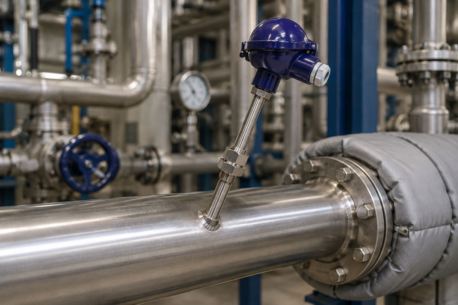
A Pt100 in a pipeline consistently indicates 4 or 5 °C less than a reference thermometer. The sensor is removed and calibrated – in the calibration bath it is almost perfectly accurate. After reinstallation, however, the measuring point again indicates a value that is too low. In such cases, the cause is often not the sensing element itself, but the thermal design of the measuring point.
A temperature sensor does not automatically measure the exact temperature of the medium simply because its tip extends into the pipeline. If the immersion depth is insufficient, heat can be conducted through the thermowell, stem, process connection and connection area to the surroundings, or heat can be transferred from the surroundings into the sensor. The sensor is then influenced by two thermal conditions: the process medium and the ambient environment.
With a hot medium and a cold environment, this typically results in a temperature reading that is too low. With a cold medium in a warm environment, the error can occur in the opposite direction. Small pipe diameters, low flow velocities, massive thermowells and large temperature differences between the process and the environment are particularly critical.
Reliable temperature measurement therefore requires more than simply selecting an accurate Pt100. Important factors include immersion depth, pipe diameter, position of the actual sensing element, thermowell geometry, flow conditions, heat conduction through the stem and insulation of the measuring point.
Suitable instruments can be found at ICS Schneider under temperature sensors and temperature probes. For measuring points where the sensor needs to remain separated from the process and replaceable, various thermowells for temperature sensors are also available.
Table of Contents
- Why immersion depth affects temperature measurement
- How heat conduction occurs through the sensor stem and connection
- When does the temperature sensor read too high or too low?
- How deep should a temperature sensor be immersed?
- Insertion length is not automatically the active sensor length
- Why small pipelines are particularly problematic
- Installation in bends, at an angle or in T-pieces
- Influence of flow velocity and medium
- Thermowell as additional thermal mass
- Measuring insert and bottom contact inside the thermowell
- Using insulation correctly at the measuring point
- Immersion depth and response time
- Special considerations for hygienic and food applications
- Typical fault patterns
- Systematic diagnostic procedure
- Performing a comparison measurement correctly
- Correcting the measuring point technically
- Practical example: Pt100 consistently reads too low
- Suitable temperature sensors and thermowells
- Conclusion
- FAQ
Why immersion depth affects temperature measurement
A temperature sensor reaches the correct measuring temperature only when the heat exchange with the medium being measured is significantly stronger than the unwanted heat exchange with the surroundings.
With a sufficiently immersed sensor, the sensor tip is predominantly influenced by the medium. Heat is transferred by convection from the medium to the thermowell or sensor stem and then to the sensing element.
If, however, the sensor extends only a few millimeters into the pipe, a large part of the metallic stem remains outside the actual medium. This stem then acts as a thermal bridge between the process and the environment.
From a thermal perspective, the measuring point then attempts to establish an equilibrium between several temperatures:
- temperature of the process medium,
- temperature of the pipe wall,
- temperature of the process connection,
- ambient temperature,
- and, where applicable, the temperature of the connection head.
As a result, the sensing element may reach a temperature somewhere between the process temperature and the ambient temperature.
In this case, the accuracy class of the Pt100 may be fully maintained – while the complete measuring point is still inaccurate.
How heat conduction occurs through the sensor stem and connection
Metallic components such as stainless steel conduct heat. A temperature sensor therefore has not only a thermal connection to the medium, but also a thermal path along its stem to the process connection and the surrounding environment.
In simplified form, heat conduction through a component section can be described by the following relationship:
Q̇ = λ · A · ΔT / L
Where:
- Q̇ = transferred heat flow,
- λ = thermal conductivity of the material,
- A = heat-conducting cross-sectional area,
- ΔT = temperature difference,
- L = length of the heat-conduction path.
The actual measuring point is considerably more complex than this simple one-dimensional model. However, it illustrates an important relationship:
A short, massive metallic heat path between the sensor and the environment promotes heat-conduction errors.
A slim sensor with sufficient immersion depth, by contrast, is influenced more strongly by the medium and less by the surroundings.
The effect becomes particularly relevant when, for example:
- the medium is at 150 °C while the ambient temperature is only 20 °C,
- a cooling line at -20 °C passes through a room at 25 °C,
- a massive threaded connection has a large metallic cross-section,
- the sensor is only immersed a very short distance into the medium.
When does the temperature sensor read too high or too low?
The direction of the measurement error generally depends on whether the ambient environment is warmer or colder than the medium.
| Situation | Typical direction of error with insufficient immersion depth |
|---|---|
| Hot medium, cold environment | Measured value tends to be too low |
| Cold medium, warm environment | Measured value tends to be too high |
| Medium and environment at similar temperatures | Heat-conduction error may hardly be noticeable |
| Strongly fluctuating ambient temperature | Measured value may drift with the environment |
The last case is particularly interesting for diagnostic purposes.
If an apparent process temperature changes noticeably with the indoor or outdoor temperature even though the actual process remains stable, the thermal coupling of the measuring point should be checked.
How deep should a temperature sensor be immersed?
There is no universal immersion depth suitable for all temperature sensors. The required length depends, among other factors, on:
- sensor diameter,
- thermowell diameter,
- material,
- pipe diameter,
- medium,
- flow velocity,
- temperature difference relative to the environment,
- position of the sensing element,
- mechanical loading of the thermowell.
As a general guideline, the sensor tip should extend into an area that is reliably surrounded by the flowing medium. In pipelines, this is typically the central region of the pipe cross-section.
For electrical thermometers, immersion depths of at least approximately 35 to 50 mm are often quoted as a general order of magnitude. However, this is not a universal design rule.
Another commonly used rule of thumb relates immersion depth to the diameter of the thermowell or sensor. Such rules of thumb are useful for an initial plausibility check, but they do not replace application-specific design.
At high flow velocities in particular, maximizing immersion depth can even become mechanically problematic. As the unsupported length increases, the flow forces acting on the thermowell increase, together with the risk of flow-induced vibration.
The design is therefore always a compromise between:
- sufficient thermal immersion depth,
- short response time,
- minimal flow obstruction,
- sufficient mechanical strength.
Insertion length is not automatically the active sensor length
When assessing an existing measuring point, it is not sufficient to consider only the visible length of the immersion stem.
The decisive factor is where the actual sensing element is located.
In a Pt100, the resistance element is usually located in the front section of the measuring insert. Depending on the sensor design, however, the active measuring zone may have a defined length or may be positioned slightly behind the extreme tip.
A nominal insertion length of, for example, 50 mm therefore does not automatically mean that the complete active sensing area is surrounded by the medium over a depth of 50 mm.
The following must also be taken into account:
- length of the threaded nozzle,
- pipe wall thickness,
- process connection,
- thermowell bottom,
- possible dead spaces.
A temperature sensor with a total insertion length of 100 mm may therefore extend only a comparatively small part of that length into the actual free pipe cross-section if it is installed in a long welded socket.
For design purposes, the effective immersion depth measured from the inner pipe wall should therefore be considered rather than simply the total sensor length.
Why small pipelines are particularly problematic
In a large process pipe, a temperature sensor can often be inserted into the central pipe region without difficulty.
This becomes significantly more difficult with small nominal pipe sizes.
An 80 mm long sensor cannot simply be installed radially in a very small pipeline. It may reach the opposite pipe wall or significantly obstruct the flow cross-section.
This creates a design conflict:
- The sensor should be immersed as deeply as possible.
- It must not excessively obstruct the pipe cross-section.
- It should be well exposed to the medium flow.
- The measuring point must remain mechanically stable.
A very short radial insertion length is therefore not automatically the best solution. It may be mechanically convenient, but can create a significant heat-conduction error.
Alternative measuring-point geometries should therefore be considered especially for small pipe diameters.
Installation in bends, at an angle or in T-pieces
If sufficient radial immersion depth is not structurally possible, the measuring point can often be designed differently.
Angled installation
The temperature sensor can be installed at an angle to the pipe axis. This provides a greater effective immersion length within the same nominal pipe diameter.
With thermowells, the mechanical loading caused by the flow must be taken into account. For angled installation, orientation should follow the manufacturer’s recommendations and engineering design requirements.
Installation in a pipe bend
Another option is installation in a pipe bend. The sensor can be positioned so that the flow impinges on the sensor tip.
This can provide a greater immersion depth even in small pipe diameters.
The position must, however, be checked from an engineering perspective. A measuring point located directly downstream of a pipe bend can be mechanically unfavorable for a long thermowell because of the local flow conditions and turbulence.
T-piece or enlarged pipe section
In test benches and smaller systems, a suitably designed T-piece or enlarged measuring section can be used to provide more space for the temperature sensor.
It must, however, be ensured that:
- the sensor is actually exposed to the main flow,
- no poorly flushed dead space is created,
- the measuring point does not become an undesirable deposition zone,
- the solution is hygienically suitable for the application.
A T-piece is therefore not automatically the solution for every measuring point with insufficient immersion depth. The actual flow around the sensor tip is decisive.
Influence of flow velocity and medium
Heat transfer from the medium to the sensor depends strongly on the flow conditions.
At higher flow velocities, the sensor tip is generally exposed more intensively to the medium. Convective heat transfer improves and the relative influence of heat conduction along the stem may decrease.
At very low flow velocities, however, a local temperature layer can develop around the sensor. Heat-conduction errors and long response times can then become more noticeable.
The medium itself also plays an important role.
Liquids typically transfer heat much more effectively than many gases. A measuring point that performs adequately in water can, with the same design, be significantly more affected by the surroundings when used in a slowly flowing gas.
Particularly critical conditions can therefore include:
- low gas velocities,
- small pipelines,
- large temperature differences relative to the surroundings,
- massive immersion stems or thermowells.
Increasing immersion depth often improves thermal coupling, but with thermowells the mechanical loading caused by the flow must also be considered.
Thermowell as additional thermal mass
A thermowell separates the actual temperature sensor from the process medium. This can, for example, allow the sensor to be replaced while the system remains in operation without opening the process.
At the same time, however, the thermowell changes the thermal behavior of the measuring point.
Several heat-transfer stages now exist between the medium and the sensing element:
- medium to the outside surface of the thermowell,
- heat conduction through the thermowell,
- heat transfer from the thermowell to the measuring insert,
- heat conduction to the actual sensing element.
A thick-walled, massive thermowell has greater thermal mass and normally responds more slowly than a slim sensor directly immersed in the medium.
The same principle therefore applies to thermowells:
The tip must extend sufficiently far into the representative process area.
At the same time, the thermowell must be mechanically designed for pressure, flow, material loading and, where applicable, flow-induced vibration.
Measuring insert and bottom contact inside the thermowell
A frequently overlooked error can occur inside the thermowell itself.
In industrial electrical thermometers, the measuring insert is often spring-loaded. This pushes its tip against the bottom of the thermowell.
This contact improves heat transfer from the thermowell to the measuring insert.
If the measuring insert is:
- too short,
- not fully inserted,
- incorrectly dimensioned,
- not correctly spring-loaded,
- not properly matched to the internal diameter,
an unnecessary air gap can develop.
Air is a poor thermal conductor. Possible consequences include:
- significantly longer response time,
- greater influence from the surroundings,
- deviations during dynamic temperature changes.
After replacing a measuring insert, it should therefore always be checked whether its length and diameter actually match the existing thermowell.
Using insulation correctly at the measuring point
Good pipe insulation can significantly reduce heat-conduction errors.
This applies particularly to:
- hot media in cold surroundings,
- cold media in warm surroundings,
- small pipelines,
- short immersion depths.
If the pipeline is insulated up to immediately before the sensor connection, unwanted heat loss through the pipe wall and process connection is reduced.
However, the insulation must not simply be extended over the entire sensor, including the connection head and transmitter, without further consideration.
Electronics, connection heads, cables and seals have specified permissible ambient temperatures. In a very hot process, insulation extending too far upward can increase the temperature inside the connection head and create new problems.
The insulation should therefore be designed specifically so that:
- the thermal influence of the surroundings on the measuring point is reduced,
- the permissible ambient temperature of the connection head and transmitter is maintained.
Immersion depth and response time
A temperature sensor can reach a plausible static value and still be unsuitable dynamically.
The response time is influenced by factors including:
- sensor diameter,
- thermowell wall thickness,
- material,
- flow velocity,
- medium,
- contact between the measuring insert and thermowell,
- immersion depth.
Insufficient immersion depth can cause the sensor, during a rapid process change, to respond not only to the medium but also to the pipe wall and surrounding environment.
Typical example:
The actual medium temperature jumps from 20 to 80 °C. A well-immersed sensor quickly approaches the new temperature. A sensor that is too short initially rises as well, but may then settle at, for example, 74 °C because heat is continuously conducted away through the stem.
This is therefore not only a response-time problem, but also a steady-state heat-conduction error.
Special considerations for hygienic and food applications
Hygienic applications present an additional design conflict.
A long sensor extending far into the pipeline may be thermally advantageous, but at the same time it may:
- affect the flow cross-section,
- promote deposits,
- reduce cleanability,
- create a dead space,
- interfere with piggable pipelines.
The temperature measuring point must therefore suit the pipeline both metrologically and hygienically.
For small hygienic pipelines, an in-line solution specifically designed for installation in piping may be more suitable than a very short standard threaded sensor.
With such solutions, the temperature measuring point is designed as part of the pipe geometry. This allows defined thermal coupling without simply inserting an excessively short thermowell into a small pipe cross-section.
Typical fault patterns with insufficient immersion depth
| Observation | Possible cause | Recommended check |
|---|---|---|
| Temperature of a hot medium is consistently indicated too low | Heat conduction through a short immersion stem or process connection | Check immersion depth and insulation |
| Cold medium is indicated too warm | Heat input from warm surroundings | Check measuring-point geometry and ambient temperature |
| Sensor is correct in the calibration bath but not in the process | Measuring-point error rather than sensor error | Investigate installation, immersion depth and flow conditions |
| Measurement deviation increases as the temperature difference to the surroundings increases | Heat-conduction error through stem or thermowell | Compare measured value with process and ambient temperature |
| Measured value responds significantly worse at low flow | Insufficient heat transfer from the medium to the sensor | Compare measurements at different flow rates |
| After replacing the measuring insert, the measuring point responds much more slowly | Measuring insert too short or poor bottom contact in the thermowell | Check length, spring travel and contact with the thermowell |
| Measured value changes after pipe insulation is installed | Previously significant ambient influence | Check measuring-point design for heat-conduction effects |
| Measured value fluctuates more strongly than the reference sensor | Different position in the flow profile or poor thermal coupling | Compare sensor positions and flow conditions |
| Very slow response despite a fast Pt100 | Massive thermowell or air gap to the measuring insert | Check thermowell and measuring insert geometry |
| Only one measuring point in an otherwise identical system shows deviations | Different insertion depth, nozzle length or insulation | Compare mechanical dimensions of the measuring points |
Systematic diagnostic procedure for implausible pipeline temperature
If a temperature sensor indicates an implausible value, electrical readjustment should not be performed immediately.
- Check process plausibility: Is there an independent temperature indication from the process?
- Record ambient temperature: How large is the difference between the medium and the surroundings?
- Identify the sensor: Pt100, thermocouple or another design?
- Check insertion length: How far does the sensor actually extend into the medium from the inner pipe wall?
- Determine the position of the sensing element: Where is the active sensing zone located?
- Check pipe diameter: Is the sensor tip located in a well-flowed area?
- Consider flow conditions: Does the error become greater at lower flow rates?
- Check the thermowell: Verify wall thickness, diameter and immersion depth.
- Check the measuring insert: Does a spring-loaded insert correctly contact the bottom of the thermowell?
- Check insulation: Is the pipeline sufficiently insulated around the measuring point?
- Perform a comparison measurement: Position the reference sensor as close as possible to the same process location.
- Only then calibrate the sensor: Once the measuring point is thermally plausible, check the sensor and transmitter.
This sequence prevents a correctly functioning Pt100 from being readjusted even though the actual error is caused by the mechanical design of the pipeline measuring point.
Performing a comparison measurement correctly
A comparison measurement is one of the best methods for detecting a heat-conduction error.
However, both sensors must actually measure as nearly as possible the same temperature.
A reference sensor should therefore:
- be installed as close as possible to the existing measuring point,
- have sufficient immersion depth,
- measure the same process condition,
- have a known measurement uncertainty.
A surface sensor installed several meters away is only of limited value as a reference for an immersed Pt100.
Useful diagnostic test
If operationally possible, the measuring point can additionally be thermally insulated.
If the previously deviating measured value moves significantly closer to the reference temperature after insulation is added, this is a strong indication that heat conduction through the pipe, nozzle or sensor stem had a relevant influence.
Such temporary insulation is, however, intended only for diagnostic purposes. The final solution should be properly engineered.
Correcting the measuring point technically
If insufficient immersion depth is identified as the cause, several solutions are possible depending on the pipeline and process.
1. Use a longer temperature sensor
If the pipe diameter is sufficiently large, a sensor with a greater insertion length may be the simplest solution.
2. Shorten the welded nozzle
An unnecessarily long nozzle can consume a large part of the nominal sensor length. A shorter process connection increases the effective immersion depth.
3. Install the sensor at an angle
With small pipe diameters, angled installation can provide a greater effective immersion depth.
4. Move the measuring point to a suitable pipe bend
Installation in a bend can allow the sensor to extend further in the direction of flow and to be more effectively exposed to the medium.
5. Use a suitable measuring section
For small pipelines, a specially designed T-piece or in-line measuring section can be useful.
6. Optimize the thermowell
A slimmer or faster-responding thermowell can improve thermal coupling, provided that pressure, flow and mechanical loading permit it.
7. Insulate the measuring point
Suitable insulation reduces the influence of ambient temperature.
8. Consider an alternative surface measurement
For very small pipe diameters, under certain conditions a well-coupled and carefully insulated surface sensor may be more suitable than an extremely short threaded immersion sensor.
The technically suitable solution depends on the required accuracy, response time, process medium and plant design.
Practical example: Pt100 consistently reads too low
In a test bench, water at a stable temperature of approximately 85 °C flows through a small stainless-steel pipeline.
However, a threaded Pt100 indicates only around 79 °C. A calibrated reference sensor at a nearby, technically better-designed measuring point indicates 84.8 °C.
Initially, a fault in the Pt100 is suspected.
Step 1: Calibrate the sensor
The Pt100 is removed and checked in a temperature calibrator or comparison bath. Its deviation there is only within the expected range.
The sensor itself is therefore unlikely to be the main cause.
Step 2: Measure the installation geometry
During the mechanical inspection, it becomes apparent that although the sensor has a nominal insertion length of 50 mm, a large portion of this length is located inside the threaded nozzle.
Measured from the inner pipe wall, the sensor tip extends only approximately 15 mm into the free pipe cross-section.
Step 3: Check the ambient influence
The pipeline is hot, while the nozzle and sensor connection are exposed to the ambient environment at approximately 22 °C.
Heat is therefore continuously conducted away through the metallic immersion stem and process connection.
Step 4: Modify the installation
The measuring point is converted to use a suitably longer sensor or a geometrically improved installation arrangement. At the same time, the pipe insulation is extended up to the permissible area of the measuring point.
Step 5: Compare again
After the modification, the temperature sensor indicates 84.5 °C. The remaining deviation from the reference is now within the expected range for the measuring chain.
Result: The Pt100 was not faulty. The insufficient effective immersion depth caused the measuring point to be influenced more strongly by the surroundings as a result of heat conduction.
The example demonstrates an important principle of temperature measurement:
Calibration confirms the characteristics of the sensor – it does not automatically confirm that the sensor measures the correct temperature in the process.
Suitable temperature sensors and thermowells for pipelines
The selection of a suitable temperature sensor should always be considered together with the mechanical design of the measuring point. Particularly relevant factors include insertion length, pipe diameter, thermowell geometry and the position of the sensing element.
WIKA TR10-B – resistance thermometer for industrial pipeline measuring points
The WIKA TR10-B is an industrial resistance thermometer that can be combined with different thermowell designs.
Depending on the version, Pt100 or Pt1000 sensors can be provided together with different:
- insertion lengths,
- neck lengths,
- connection heads,
- thermowell dimensions
.
The spring-loaded replaceable measuring insert is particularly relevant for measuring points with a thermowell. When correctly dimensioned, the insert is pressed against the thermowell bottom, ensuring good thermal coupling.
Particularly in pipelines, the insertion length should not simply be selected according to an available standard dimension. The decisive factor is how far the thermowell tip actually extends into the free pipe cross-section after installation.
Further information can be found under WIKA TR10-B resistance thermometer at ICS Schneider.
WIKA TR25 – in-line resistance thermometer for hygienic applications
In hygienic pipelines, a conventional long thermowell may be undesirable from a design perspective.
The WIKA TR25 in-line resistance thermometer is designed for temperature measurement in pipelines with high hygienic requirements.
The design is particularly suitable for applications in which a thermowell extending far into the process is either not possible or not desired, for example in:
- food and beverage installations,
- dairies,
- biotechnology and pharmaceutical applications,
- piggable pipelines,
- high-viscosity media.
For small hygienic pipelines, such an in-line solution can be technically more suitable than designing a conventional measuring point with only a very short immersion stem.
Further information can be found under WIKA TR25 in-line resistance thermometer at ICS Schneider.
Selecting the correct thermowell for the measuring point
A thermowell protects the actual temperature sensor against process pressure, flow, corrosion and mechanical loading and, depending on the installation, allows the thermometer to be replaced without opening the process.
For accurate temperature measurement, however, the thermowell must be correctly dimensioned both mechanically and thermally.
Factors to be considered include:
- immersion depth,
- outside and tip diameter,
- wall thickness,
- material,
- process pressure,
- flow velocity,
- vibration loading,
- required response time.
At high flow velocities or with long thermowells, an additional mechanical thermowell calculation may be required.
An overview of different versions can be found under thermowells at ICS Schneider.
Conclusion
An incorrect temperature indication in a pipeline does not automatically mean that the Pt100 or thermocouple itself is inaccurate.
Particularly in small pipe diameters, an insufficient effective immersion depth can cause the sensor to be influenced not only by the process medium. Heat is conducted through the sensor stem, thermowell and process connection to the surroundings or transferred from the surroundings into the measuring point.
With hot media, this typically results in a reading that is too low; with cold media, the reading tends to be too high.
For a reliable measuring point, the sensor tip should be positioned as far as possible in a well-flowed, representative region of the pipeline. At the same time, thermowell loading, flow conditions, pipe diameter, response time and process requirements must be considered.
In small pipelines, angled installation, installation in a suitable pipe bend, a dedicated measuring section or an in-line solution can be technically more suitable than a very short radially installed sensor.
A correctly dimensioned measuring insert inside the thermowell and suitable insulation are also important aspects of measuring-point quality.
The following rule therefore applies to troubleshooting: First check the thermal and mechanical installation conditions, then perform a comparison measurement – and only after that evaluate the sensor itself as a possible source of error.
FAQ: Immersion depth and heat conduction in temperature sensors
Why does a temperature sensor in a pipeline indicate too low a temperature?
With a hot medium, insufficient immersion depth can cause heat to be conducted through the sensor stem, process connection or thermowell to the cooler surroundings. The sensing element then reaches a lower temperature than the actual medium.
Can a Pt100 be correctly calibrated and still measure incorrectly in the process?
Yes. Calibration evaluates the sensor under defined thermal conditions. In the process, immersion depth, heat conduction, flow conditions or thermowell geometry can introduce additional measurement errors.
How deep must a Pt100 be immersed in a pipeline?
There is no universal immersion depth. As a general guideline, the active sensing area should be reliably surrounded by the medium and should extend into a representative region of the pipe cross-section. For electrical thermometers, at least approximately 35 to 50 mm is often mentioned as a general order of magnitude, but the specific application must always be considered separately.
Does a temperature sensor have to reach the center of the pipe?
Not necessarily exactly to the geometric center of the pipe. The important point is that the sensor tip is sufficiently immersed in a representative, well-flowed region. The central third of the pipe cross-section is a commonly used guideline.
Why is insufficient immersion depth problematic?
The shorter the immersed section, the greater the heat flow through the sensor stem and process connection can become relative to the heat exchange with the medium. As a result, the sensor temperature can shift toward the ambient temperature.
Does a temperature sensor that is too short always read too low?
No. The direction of the error depends on the temperature difference relative to the surroundings. With a hot medium and cooler surroundings, the indicated value is usually too low. With a cold medium and warmer surroundings, it may instead be too high.
Why is temperature measurement more difficult in small pipelines?
Small pipes provide only limited radial insertion length. A sufficiently long sensor can significantly obstruct the flow cross-section or reach the opposite pipe wall. Alternative installation geometries are therefore often required.
Can a temperature sensor be installed at an angle?
Yes. Angled installation can provide a greater effective immersion depth, particularly in small pipe diameters. With thermowells, however, the direction of flow and mechanical loading must be taken into account.
Can a temperature sensor be installed in a pipe bend?
Yes. Suitable installation in a pipe bend can be useful for small pipelines because the sensor can extend further along the direction of flow. The sensor tip should be exposed to the flow in accordance with the intended design.
Is a T-piece useful for a temperature sensor?
A suitably designed T-piece or enlarged measuring section can provide additional immersion depth. It must, however, be ensured that the sensor is reached by the main flow and that no poorly flushed dead space is created.
How does flow velocity influence temperature measurement?
Higher flow velocity often improves heat transfer from the medium to the sensor and reduces response time. At the same time, the mechanical loading on a thermowell increases with flow velocity.
Why do temperature sensors often respond more slowly in gases than in liquids?
Gases generally provide poorer heat transfer than liquids. The sensor may therefore respond more slowly and the relative influence of heat conduction through the stem may become greater.
What effect does a thermowell have on temperature measurement?
A thermowell increases mechanical protection and often allows the sensor to be replaced without opening the process. At the same time, it adds thermal mass between the medium and the sensing element, which can increase response time.
Why must the measuring insert contact the bottom of the thermowell?
In many electrical thermometers, the measuring insert is spring-loaded against the bottom of the thermowell. This improves heat transfer. An air gap between the measuring insert and thermowell can significantly slow the response.
Can a measuring insert that is too short cause measurement errors?
Yes. If the sensor tip does not correctly contact the bottom of the thermowell, thermal coupling deteriorates. This can particularly affect response time and behavior during changing temperatures.
Does pipe insulation help reduce heat-conduction errors?
Yes. Suitable insulation can significantly reduce the influence of the environment on the pipeline, connection nozzle and sensor stem. However, the permissible ambient temperatures of the connection head, cable and any installed transmitter must still be observed.
How can a heat-conduction error be detected?
A comparison measurement using a correctly installed reference sensor can be helpful, as can observing the measured value at different ambient temperatures or after improving the insulation. If the deviation changes significantly, this indicates a thermal installation error.
Why does the error increase when the temperature difference to the surroundings becomes larger?
As the temperature difference increases, the possible heat flow through the stem and connection also increases. A poorly installed sensor will therefore usually be influenced more strongly by the environment when measuring a medium at 150 °C in a 20 °C environment than when measuring a medium at 30 °C.
Which temperature sensor is suitable for conventional industrial pipelines?
For industrial pipeline measuring points, a resistance thermometer such as the WIKA TR10-B with a suitably designed thermowell can be used. The decisive factor is selecting the correct insertion length and thermowell geometry for the specific measuring point.
Which solution is suitable for small hygienic pipelines?
For hygienic applications, an in-line solution specifically designed for pipeline installation can be useful. The WIKA TR25, for example, is designed for temperature measurement in hygienic pipelines where a conventional thermowell extending into the process is either not possible or not desired.
When should a thermowell be mechanically calculated?
At high flow velocities, high process pressures, large immersion depths or critical thermowell geometries, the mechanical loading of the measuring point should be evaluated. In particular, flow-induced vibration and the permissible mechanical loading of the thermowell must be considered.