


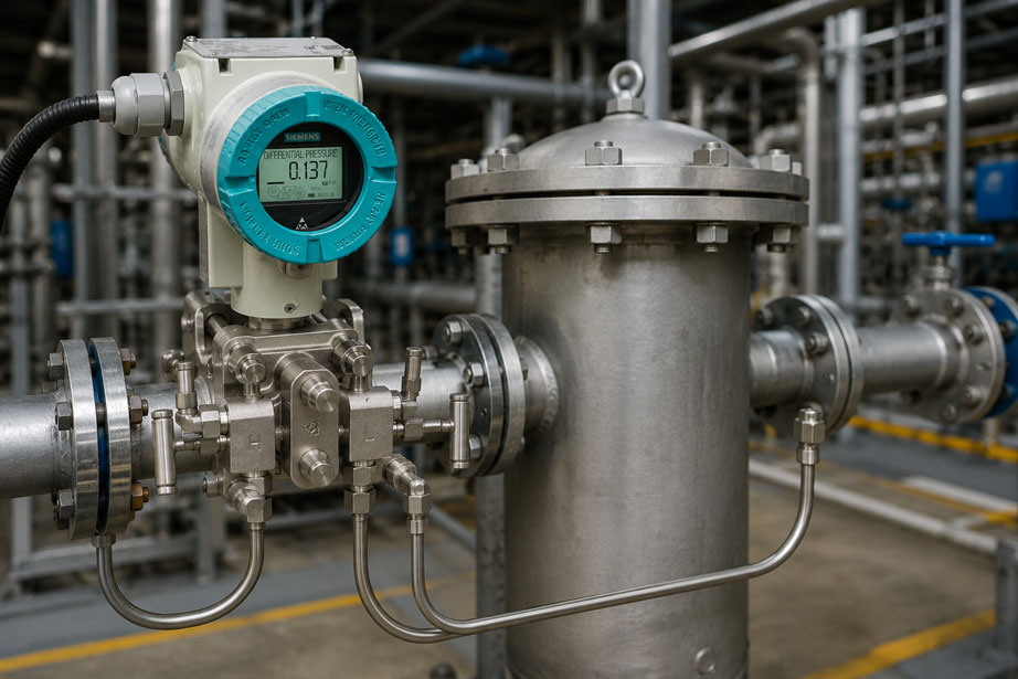
The differential pressure across a filter continues to increase – even though the filter was replaced only a few days ago. Or the measured value suddenly remains almost constant even though the flow rate and operating conditions change significantly. In such cases, the differential pressure transmitter is often suspected first. In practice, however, the cause is frequently located between the process and the measuring instrument: in the impulse lines, at the pressure tapping points, in the valve manifold or in an unequal liquid fill of the measuring lines.
Particularly with small differential pressures, even a few centimeters of condensate column can cause a significant measurement error. In liquid filters, trapped gas bubbles can affect the measurement; in gas filters, accumulated condensate can have the same effect. Deposits can partially or completely block an impulse line. The measuring instrument itself may therefore be operating perfectly correctly – it simply no longer receives the correct process pressures.
Reliable filter monitoring must therefore consider the entire measuring chain: high-pressure side, low-pressure side, pressure tapping points, impulse lines, valve manifold, fill condition, installation position and zero point of the differential pressure transmitter.
Suitable measuring instruments can be found at ICS Schneider under pressure sensors and differential pressure sensors. For simple limit monitoring, pressure switches and differential pressure switches are also available.
Table of Contents
- How differential pressure indicates filter condition
- Connecting the high- and low-pressure sides correctly
- Why flow rate must be considered in the evaluation
- Impulse lines as part of the measurement
- How condensate causes incorrect differential pressure readings
- Gas bubbles in liquid filter applications
- Detecting clogged impulse lines
- Valve manifold, isolation and pressure equalization
- Zero-point errors and installation position
- Frost and frozen impulse lines
- Selecting the correct measuring range and static pressure rating
- Evaluating filter condition using trend data
- Defining warning and replacement limits correctly
- Typical fault patterns
- Systematic diagnostic procedure
- Practical example: filter suddenly appears clogged
- Suitable differential pressure instruments
- Conclusion
- FAQ
How differential pressure indicates filter condition
A filter creates flow resistance. With the normal direction of flow, the pressure upstream of the filter is therefore higher than the pressure downstream of the filter.
The differential pressure can be expressed in simplified form as:
Δp = pH − pL
Where:
- pH = pressure on the high-pressure side upstream of the filter,
- pL = pressure on the low-pressure side downstream of the filter,
- Δp = pressure drop across the filter element.
A clean filter has a characteristic initial pressure drop at a defined flow rate. As particles accumulate in the filter medium, flow resistance increases. At a comparable flow rate, the differential pressure therefore normally increases.
Typical conditions include:
| Observation | Possible interpretation |
|---|---|
| Low and stable Δp | Clean filter or low flow rate |
| Slowly increasing Δp | Increasing filter loading |
| Very high Δp | Heavily loaded or blocked filter |
| Sudden significant drop | Reduced flow, bypass open, damaged filter or measurement error |
| Suddenly constant value despite process changes | Blocked impulse line or frozen pressure transmission possible |
Differential pressure is therefore an excellent condition parameter – but only if both process pressures reach the measuring instrument without distortion.
Connecting the high- and low-pressure sides correctly
A differential pressure transmitter has two pressure connections. These are usually identified as High or H and Low or L.
For a filter with the normal direction of flow:
- H side: pressure tapping point upstream of the filter,
- L side: pressure tapping point downstream of the filter.
If the two connections are reversed, the measuring instrument receives a negative differential pressure or a signal with the opposite sign. Depending on the configuration, this may appear as a negative measured value, underrange condition or apparently implausible output signal.
Particularly after maintenance work, the following should therefore be checked:
- Which line actually comes from the filter inlet side?
- Which line comes from the filter outlet side?
- Is the H line actually connected to H?
- Is the L line actually connected to L?
- Does the transmitter configuration correspond to the required measuring direction?
For longer pipe runs, the assignment should be permanently identified. Relying solely on hose colors or historical labels can lead to errors after modifications.
Why flow rate must be considered in the evaluation
One frequently overlooked factor is the dependence of filter pressure drop on the volumetric or mass flow rate.
The differential pressure across a filter is not purely a measure of contamination. If more medium flows through the same filter, the pressure drop normally also increases.
This means:
A filter differential pressure of 80 mbar at maximum flow is not automatically worse than 60 mbar at a significantly lower flow rate.
The current flow rate must be considered particularly in systems with:
- variable-speed fans,
- speed-controlled pumps,
- variable production rates,
- changing valve positions,
- parallel filter trains.
For trend analyses, differential pressure values should therefore ideally be evaluated under comparable operating conditions. Alternatively, the control system can record differential pressure, flow rate and, where applicable, rotational speed together.
A universal correction factor should not be applied without knowledge of the filter characteristic. The relationship between flow and pressure drop depends on filter type, medium, filter loading and flow conditions.
Impulse lines as part of the measurement
The two small pipes or hoses between the process and the differential pressure transmitter are commonly referred to as impulse lines.
Their task sounds simple: they transmit the static pressure from the two process points to the measuring instrument.
In practice, however, these lines are among the most frequent causes of incorrect differential pressure measurements.
Typical problems include:
- deposits or particles in the line,
- condensate in gas impulse lines,
- gas bubbles in liquid impulse lines,
- different liquid columns on the H and L sides,
- leaks,
- kinked hoses,
- closed or partially closed valves,
- frost,
- different line routing.
A highly accurate transmitter cannot detect or compensate for these errors if incorrect pressures are already present at its two connections.
The impulse line should therefore be considered part of the entire measuring chain rather than merely a mechanical connection to the process.
How condensate causes incorrect differential pressure readings
Particularly in gas, compressed-air and humid process-gas applications, liquid can accumulate in an impulse line.
Possible causes include:
- cooling of the process gas,
- falling below the dew point,
- unfavorable low points in the line,
- lack of a drainage facility,
- temperature differences between the two lines.
A different amount of condensate on the H and L sides is particularly problematic.
A liquid column generates additional hydrostatic pressure:
Δphyd = ρ · g · Δh
Where:
- ρ = density of the liquid,
- g = gravitational acceleration,
- Δh = height difference of the liquid column.
Even a few centimeters can be significant
For water, an additional liquid column of 50 mm corresponds approximately to:
Δp ≈ 1000 kg/m³ · 9.81 m/s² · 0.05 m ≈ 490 Pa ≈ 4.9 mbar
For a filter measurement in the range of only a few tens of millibar, this already represents a significant error.
The decisive factor is not whether liquid is present in principle, but whether the H and L sides have hydrostatically comparable conditions.
Condensate pots are not a universal solution
In applications where a defined liquid column is technically required – for example in certain steam or condensate applications – condensate pots or defined wet legs can be used.
In such cases, both sides must have controlled and, as far as possible, identical hydrostatic conditions.
In a normal gas filter measurement, however, the objective is often to keep condensate out of the impulse lines or to drain it in a controlled manner. The correct line arrangement therefore depends on the medium and the specific system design.
Gas bubbles in liquid filter applications
In liquid applications, the opposite problem occurs: the impulse lines should normally be completely filled with liquid.
If a line contains a trapped gas bubble, pressure transmission becomes compressible. As a result, the measured value may:
- respond more slowly,
- follow rapid pressure changes with a delay,
- respond differently on the H and L sides,
- initially appear unstable after maintenance work.
Typical causes include:
- insufficient venting after maintenance,
- high points in the pipe routing,
- outgassing of the medium,
- leaks through which air enters the system.
In liquid measurements, impulse lines should therefore be designed and commissioned so that trapped gases can be safely vented in accordance with the system design.
Detecting clogged impulse lines
Deposits can gradually clog an impulse line. Small line diameters and processes involving the following are particularly critical:
- dust,
- sludge,
- crystallization,
- corrosion products,
- sticky process components,
- solids in the medium.
A completely blocked line no longer transmits pressure changes correctly. A partially blocked line, on the other hand, can act like a severe restriction.
Typical behavior of a partially clogged line
The measured value still responds, but unusually slowly.
For example, the actual pressure upstream of the filter suddenly increases. The unrestricted H side follows this change immediately, while a partially clogged L side responds with a significant delay. During this transition period, an incorrect differential pressure is displayed.
Typical behavior of a completely blocked line
The pressure in the blocked line can effectively become “frozen”. The measuring instrument then compares a current process pressure with an old trapped pressure.
Depending on which side is blocked and how the process subsequently changes, the displayed differential pressure may therefore be:
- too high,
- too low,
- almost constant over an extended period.
For this reason, the direction of the measurement error alone does not always clearly indicate which impulse line is blocked.
Valve manifold, isolation and pressure equalization
Industrial differential pressure transmitters are frequently fitted with a 3- or 5-valve manifold.
Depending on the design, such a manifold can provide functions including:
- isolating the high-pressure side,
- isolating the low-pressure side,
- equalizing the two measuring chambers,
- venting or draining,
- connecting a test instrument.
Equalization is particularly useful for diagnostics. If both transmitter sides are exposed to the same pressure under defined conditions, the differential pressure should ideally be close to zero.
If the transmitter shows a significant value in the equalized condition, possible causes include:
- zero-point shift,
- installation-position effect,
- unequal liquid columns,
- contaminated valve passages,
- an actual sensor fault.
The specific valve operating sequence must always follow the operating instructions for the measuring instrument and the plant’s operating procedure. At high static pressures, an incorrect valve sequence can expose the differential pressure sensor to excessive one-sided pressure.
Zero-point errors and installation position
A differential pressure transmitter may display a small value even when nominally the same pressure is applied to both inputs.
One possible cause is the installation position. With sensitive differential pressure measuring cells, changes in orientation can cause a zero-point shift due to mechanical effects or internal fill fluids.
A zero-point or position adjustment should therefore only be performed once the instrument:
- has been finally installed,
- is in its intended mounting position,
- has correctly filled or vented impulse lines,
- is thermally stable.
Zero adjustment must not hide an installation error
A very important point:
A zero trim should not be used to compensate for an unequal condensate column or an incorrectly filled impulse line.
If, for example, an additional 50 mm water column on one side were simply trimmed out, the indication would only remain correct for as long as this liquid column remained exactly the same.
If condensate evaporates or additional liquid accumulates, the error will reappear.
The hydraulic or pneumatic conditions should therefore be corrected first – and only then should the zero point be checked.
Frost and frozen impulse lines
In outdoor installations and cold process areas, condensate in an impulse line can freeze.
In the worst case, a frozen line behaves like a completely closed line. The process pressure then no longer reaches the differential pressure transmitter.
Particularly vulnerable are:
- low points containing accumulated condensate,
- small uninsulated pipes,
- outdoor-mounted valve manifolds,
- measuring points with frequent transitions between warm and cold process conditions.
Depending on the process and system requirements, suitable countermeasures can include:
- line routing designed for condensate management,
- avoiding unnecessary low points,
- thermal insulation,
- suitable heat tracing,
- protected installation of the transmitter,
- regular drainage.
Heat tracing and frost protection must, however, be suitable for the medium, hazardous area classification and permissible temperature of the measuring instrument and impulse lines.
Selecting the correct measuring range and static pressure rating
In filter measurements, the actual differential pressure is often small while the absolute process pressure can be very high.
Example:
A process gas filter operates at a line pressure of 25 bar, while the expected filter pressure drop is only 50 to 300 mbar.
The measuring instrument must therefore simultaneously:
- resolve the small differential pressure with sufficient accuracy,
- withstand the high static pressure on both sides,
- withstand possible one-sided overloads when valves are operated or during process disturbances.
When selecting the instrument, not only measuring span and accuracy should therefore be considered, but also:
- maximum permissible static pressure,
- one-sided overload capability,
- media compatibility,
- process temperature,
- pressure connections,
- materials and seals,
- required hazardous-area approvals.
Selecting the smallest possible measuring range does not automatically improve every measurement if operating or overload limits are exceeded as a result.
Evaluating filter condition using trend data
A continuous differential pressure signal offers one major advantage over a simple switching contact: the development of filter condition becomes visible.
A typical filter trend shows:
- a defined initial pressure drop after filter replacement,
- a slowly increasing differential pressure as the filter becomes loaded,
- the point at which the maintenance or replacement range is reached.
Unusual trend patterns, on the other hand, can indicate measurement problems.
| Trend | Possible cause |
|---|---|
| Slow, steady increase | Normal increasing filter loading |
| Sudden increase | Sudden filter loading, process change, condensate or line problem |
| Sudden decrease | Reduced flow, bypass, filter failure or impulse-line problem |
| Completely flat trend over a long period | Constant process or blocked pressure transmission |
| Very slow response to known process changes | Partially clogged impulse line or gas pocket |
| Shift depending on time of day | Possible temperature, condensate or frost problem |
Diagnosis becomes particularly informative when differential pressure is recorded together with flow rate, pump or fan speed and operating condition.
Defining warning and replacement limits correctly
A differential pressure switch or PLC requires a limit at which a warning or filter replacement is triggered.
This limit should not be selected arbitrarily.
The basis should include:
- filter manufacturer’s specifications,
- permissible final pressure drop of the filter element,
- nominal flow rate,
- permissible energy consumption of the system,
- required process performance,
- experience from actual operation.
Several thresholds can be useful:
- Pre-warning: filter is approaching the maintenance range.
- Maintenance limit: schedule filter replacement or cleaning.
- Alarm limit: permissible operating range is being exceeded.
With strongly variable flow rates, however, a simple fixed limit alone can result in false alarms. The filter manufacturer or system designer should define the operating conditions to which the permissible final pressure drop applies.
Typical fault patterns in filter differential pressure measurement
| Observation | Possible cause | Recommended check |
|---|---|---|
| Differential pressure remains high after filter replacement | Condensate, zero-point error, incorrect valve position or blocked line | Check valve manifold, impulse lines and zero condition |
| Differential pressure suddenly increases without an obvious process change | Condensate accumulation or partially clogged line | Check H and L lines for liquid and deposits |
| Differential pressure remains constant despite changes in pump or fan speed | One or both impulse lines blocked | Check pressure transmission and response of both sides |
| Measured value responds unusually slowly | Partial blockage, gas bubble or severely restricted line | Vent lines or check them for free passage |
| Measured value shows a negative sign after maintenance | H and L lines reversed | Check connection assignment |
| Zero point shifts after installation | Installation position or hydrostatic liquid column | Check mounting position and line fill condition |
| Measured value changes significantly with outdoor temperature | Condensation, density change of a liquid column or frost | Investigate line routing and temperature conditions |
| Filter appears more clogged at night than during the day | Temperature-related condensation in a gas impulse line possible | Compare trend with ambient temperature |
| Measured value suddenly approaches zero | Plant shutdown, bypass open, filter rupture or nearly equal pressure on both sides | Check flow rate and system condition |
| Transmitter does not indicate zero with the valve manifold equalized | Zero-point shift or unequal liquid columns | Correct installation conditions and then check zero point |
Systematic diagnostic procedure for incorrect filter differential pressure
If the differential pressure is implausible, the transmitter should not immediately be removed or recalibrated. A more useful approach is to check the system from the process connection through to the measuring instrument.
- Check the process condition: Is the system actually operating at the expected flow rate?
- Check filter condition: Was the filter recently replaced or cleaned?
- Check H and L assignment: Are the upstream and downstream filter sides connected correctly?
- Check valve positions: Are the isolation and equalizing valves fully in their normal operating positions?
- Check pressure tapping points: Are the process openings free?
- Inspect the impulse lines: Are there kinks, low points, condensate or visible deposits?
- Drain gas applications: Check condensate in accordance with the intended design.
- Vent liquid applications: Rule out trapped gas bubbles.
- Check response behavior: Do both sides follow known process changes plausibly?
- Equalize the transmitter: Bring both sides to the same pressure in accordance with the plant procedure.
- Evaluate the zero point: Only check zero or position correction once the measuring chain is correctly filled and vented.
- Check the electrical signal: Verify the 4–20 mA signal, scaling and control system.
- Only then calibrate: Once process connections and impulse lines have been ruled out, perform a metrological check of the transmitter.
This procedure prevents a correctly operating differential pressure transmitter from being removed and calibrated when the actual cause is a blocked measuring line.
Practical example: filter suddenly appears clogged
In a process gas system, a filter is continuously monitored by a differential pressure transmitter. After the filter has been replaced, the normal differential pressure is approximately 35 mbar.
Several weeks later, the indication rises to 75 mbar within a few hours. The flow rate and the other process parameters remain almost unchanged.
The initial assumption is that the new filter has become clogged unusually quickly.
Step 1: Compare process data
The flow rate has not increased significantly. A throughput-related increase in filter pressure drop is therefore unlikely.
Step 2: Examine the trend
The differential pressure did not increase gradually, but rose suddenly within a short period. This does not match the previous filter loading behavior.
Step 3: Inspect the impulse lines
During the visual inspection, it becomes apparent that the line to the low-pressure side has a low point. Condensate has accumulated there.
Step 4: Eliminate the hydrostatic influence
The line is drained in accordance with the plant procedure and the line routing is checked.
Step 5: Check the zero point
After pressure equalization via the valve manifold, the transmitter is again close to its correct zero point.
After recommissioning, the differential pressure is 39 mbar.
Result: The filter was not unusually heavily contaminated. An unequally filled impulse line had generated an additional hydrostatic pressure.
This example demonstrates: At low differential pressures, the quality of the impulse lines can have a greater influence on the measurement result than the nominal accuracy of the transmitter.
Suitable differential pressure instruments for filter monitoring
The appropriate measuring technology depends strongly on the medium, differential pressure range, static process pressure and required evaluation. A differential pressure transmitter is useful for continuous trend monitoring. For simple limit indication, a differential pressure switch may be sufficient.
Siemens SITRANS P320 – for continuous differential pressure measurement in process applications
The Siemens SITRANS P320 is suitable for demanding process applications and is available, among other configurations, for differential pressure measurement.
For filter monitoring, continuous measured-value transmission is particularly useful. Differential pressure can therefore not only be monitored against a fixed limit, but also evaluated as a trend via the control system.
Depending on the instrument version, available features include:
- 4–20 mA signal with HART communication,
- diagnostic functions according to NAMUR NE107,
- different measuring ranges for process pressure and differential pressure,
- versions for demanding process media,
- different wetted materials.
The SITRANS P320 is therefore particularly suitable for filter systems in the process industry where, in addition to the current differential pressure, diagnostics, parameterization and long-term measurement trends are relevant.
Further information can be found under Siemens SITRANS P320 at ICS Schneider.
WIKA DPT-20 – differential pressure transmitter for filter and process applications
Another solution for industrial differential pressure measurement is the WIKA DPT-20.
The transmitter is intended, among other applications, for filter and pump monitoring and, depending on the version, offers:
- scalable differential pressure measuring ranges,
- 4–20 mA or 4–20 mA with HART,
- high static pressure capability,
- different housing and process configurations.
The instrument is therefore particularly suitable for industrial filter measuring points where a comparatively small differential pressure must be measured while a significantly higher process pressure is present.
WIKA A2G-40 – simple filter limit monitoring in ventilation systems
In ventilation and air-conditioning systems with dry, clean and non-aggressive air, continuous process measurement is often not required. A mechanical or electromechanical differential pressure switch can be useful in such applications.
The WIKA A2G-40 is specifically designed for air-conditioning and ventilation applications and can be used, among other things, to monitor filters and fans.
Such a switch is suitable, for example, for the indication:
“Filter differential pressure exceeded – check or replace filter.”
Further information can be found under WIKA A2G-40 differential pressure switch at ICS Schneider.
Transmitter or switch?
| Requirement | Suitable solution |
|---|---|
| Warning only when the filter is contaminated | Differential pressure switch |
| Display the current Δp value in the control system | Differential pressure transmitter |
| Evaluate filter loading as a trend | Differential pressure transmitter with analog or digital signal |
| High static process pressure with low Δp | Suitable process differential pressure transmitter |
| HVAC with dry air and a simple limit value | Low-pressure differential pressure switch |
Further instruments can be found under pressure sensors and differential pressure sensors at ICS Schneider as well as under pressure switches and differential pressure switches.
Conclusion
Differential pressure is one of the most important parameters for monitoring filters. An increasing value can indicate increasing filter loading – but only if the measuring chain is operating correctly and the operating conditions are comparable.
If measured values are implausible, the transmitter should therefore not automatically be suspected. Condensate, gas bubbles, clogged impulse lines, incorrect valve positions and hydrostatic differences can cause significantly greater errors than the sensor itself.
Particularly at low differential pressures, even small liquid columns are sufficient to cause significant zero-point shifts. Zero adjustment must not simply be used to compensate for such installation errors. Both impulse lines must first be brought into a defined hydraulic or pneumatic condition.
For condition monitoring, it is also essential not to evaluate differential pressure in isolation. Filter pressure drop, flow rate and operating condition belong together. Trend recording can help distinguish normal filter loading from a suddenly occurring measurement problem.
The most important troubleshooting rule is therefore: First check the process and impulse lines, then the zero point and electrical signal – and only then calibrate or replace the differential pressure transmitter.
FAQ: Differential pressure measurement across filters
How is differential pressure measured across a filter?
The pressure upstream of the filter is connected to the high-pressure side of the differential pressure instrument, while the pressure downstream of the filter is connected to the low-pressure side. The instrument calculates the difference pH − pL.
Why does differential pressure increase when a filter becomes contaminated?
As particle loading increases, the flow resistance of the filter medium normally increases. At a comparable flow rate, a greater pressure drop is therefore required to force the medium through the filter.
Can high differential pressure occur even if the filter is not clogged?
Yes. Possible causes include a higher flow rate, condensate in an impulse line, a zero-point error, an incorrect valve position or a blocked impulse line.
Why must flow rate be considered when monitoring a filter?
The pressure drop across a filter depends not only on contamination but also on the amount of medium flowing through it. Differential pressure values are therefore particularly meaningful when the operating conditions are similar.
What is an impulse line?
An impulse line connects a process pressure tapping point to the differential pressure measuring instrument. In filter monitoring, one line is connected to the upstream side and one to the downstream side of the filter.
How can a clogged impulse line be detected?
Typical indications include an unusually slow measured value, an almost unchanged value despite process changes or a suddenly implausible differential pressure. The free passage of both lines must then be checked individually.
Can a blocked high-pressure line cause a reading that is too low?
Yes. The direction of the error depends on which line is blocked and how the process pressures subsequently change. A blocked line can trap an old pressure and therefore cause either an excessively high or excessively low differential pressure.
Why does condensate cause a measurement error?
A liquid column generates hydrostatic pressure. If more liquid is present on one side of the differential pressure measuring system than on the other, an additional pressure component is created and measured by the transmitter as part of the differential pressure.
How large is the error caused by a 5 cm water column?
A water column of 50 mm generates approximately 490 Pa or 4.9 mbar of hydrostatic pressure. In a low-range filter differential pressure measurement, this can already represent a significant proportion of the measuring range.
What happens if there is a gas bubble in a liquid impulse line?
The trapped gas is compressible. Pressure transmission can therefore be delayed or damped. Particularly during rapid process changes, this can result in different response times on the H and L sides.
What is the purpose of a 3-valve manifold on a differential pressure transmitter?
A 3-valve manifold normally allows the two process sides to be isolated and the high- and low-pressure sides to be connected or equalized. This allows the zero point to be checked under defined conditions, for example.
What is the difference between a 3-valve and a 5-valve manifold?
A 5-valve manifold includes additional valves for venting, draining or connecting test instruments. The exact function depends on the specific manifold design.
When should the zero point of a differential pressure transmitter be adjusted?
The zero point should only be checked or corrected once the transmitter has been finally installed, the impulse lines have been correctly filled or vented and both sides have been brought to the same pressure under defined conditions.
Can a condensate error simply be compensated by zero adjustment?
This is not advisable. If the height of the liquid column subsequently changes, the hydrostatic error will also change. The cause of the unequal liquid columns must therefore be eliminated first.
Why does a differential pressure transmitter show different values in winter?
At outdoor measuring points, condensation, temperature-dependent liquid columns or even frozen impulse lines can affect the measurement. Line routing, frost protection and temperature conditions should therefore be checked.
How can a filter rupture be detected using differential pressure?
A sudden significant drop in filter pressure loss can indicate a damaged filter or bypassing of the filter element. However, a reduced flow rate or measurement error can cause the same observation. The process condition must therefore also be considered.
How should the limit for filter replacement be defined?
The replacement limit should be based on the filter manufacturer’s specifications and the actual operating conditions. Important parameters include permissible final pressure drop, nominal flow rate and system performance.
Is a differential pressure switch or a differential pressure transmitter better?
A differential pressure switch may be sufficient for simple limit indication. If filter condition is to be recorded continuously, displayed in the control system or evaluated as a trend, a differential pressure transmitter is the more suitable solution.
Why is a trend more useful than an alarm contact alone?
A trend shows whether differential pressure is increasing gradually as the filter becomes loaded or whether it changes suddenly. This makes maintenance and troubleshooting easier to plan and allows measurement problems to be detected earlier.
What should be checked first if the filter differential pressure is implausible?
First check the process condition, flow rate, H/L connections, valve positions, pressure tapping points and impulse lines. Only after these causes have been ruled out should the zero point, output signal and calibration of the differential pressure transmitter be investigated in more detail.