


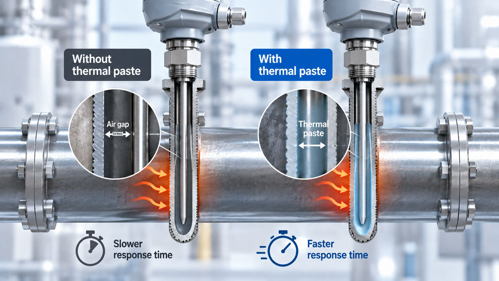
A Pt100 resistance thermometer monitors the temperature of an industrial pipeline. The sensor is installed as a replaceable measuring insert inside a metallic thermowell. Although the Pt100 is correctly calibrated, the temperature indication responds unusually slowly to temperature changes.
During an inspection, it becomes apparent that the measuring insert has a significantly smaller outside diameter than the thermowell bore. An air gap exists between the two components, impairing heat transfer.
One possible solution is thermal paste. It can reduce the thermal resistance of the gap and thereby improve response time.
However, thermal paste is not necessarily the best solution for every temperature measuring point. Depending on the product and operating temperature, it may age, dry out, harden or leave residues. This can make subsequent replacement of the measuring insert more difficult.
Particularly in industrial thermowell assemblies with spring-loaded measuring inserts, heat transfer, temperature resistance and maintainability must therefore be considered together.
This article explains the effects of air gaps, highlights the limitations of thermal compounds and shows how fast temperature measurement can be combined with a permanently service-friendly design.
Table of Contents
- Measurement Task and Typical Problems
- Design of a Temperature Measuring Point with Thermowell
- Heat Transfer from the Process to the Sensor
- Influence of the Air Gap
- How Thermal Paste Works
- Thermal Paste or a Properly Fitting Measuring Insert?
- Selecting a Suitable Thermal Compound
- Practical Example: Thermal Resistance in the Annular Gap
- Correctly Evaluating Temperature Resistance
- Ageing, Drying Out and Hardening
- Considering Future Sensor Replacement
- Insertion Length and Tip Contact
- Measuring Insert and Thermowell Diameters
- Applying Thermal Paste Correctly
- Filling Quantity and Distribution
- Response Time and Measurement Dynamics
- Steady-State Measurement Deviations
- Diagnosing Slow Temperature Measurement
- Calibration and Functional Testing
- Operational Safety and Process Conditions
- Testing and Installation Procedure
- Suitable ICS Products
- Conclusion
- Frequently Asked Questions
1. Measurement Task and Typical Problems
In a suitable configuration, a thermowell allows the actual temperature measuring insert to be replaced without opening the process-side thermowell connection.
However, the additional metallic wall and a possible air gap influence heat transfer.
A slow temperature indication can therefore occur even with a fully functional Pt100 or thermocouple. Before thermal paste is used, the mechanical design of the measuring point should be checked.
2. Design of a Temperature Measuring Point with Thermowell
A typical industrial measuring point consists of a thermowell, a replaceable measuring insert and a connection head or temperature transmitter.
The process first heats or cools the thermowell wall. Heat is then transferred to the tip of the measuring insert and finally to the temperature-sensitive sensing element.
The WIKA TR10-B, for example, uses a spring-loaded, replaceable measuring insert. When correctly dimensioned, the spring provides the intended contact with the thermowell tip.
3. Heat Transfer from the Process to the Sensor
The heat transfer path includes several thermal resistances:
- Heat transfer between the process medium and the thermowell.
- Heat conduction through the thermowell material.
- Heat transfer between the thermowell and the measuring insert.
- Heat conduction to the temperature-sensitive sensing element.
A large air gap can cause additional thermal resistance. Insufficient immersion depth and heat dissipation through the connection area can also influence the measurement result.
4. Influence of the Air Gap
Air has a significantly lower thermal conductivity than typical metallic thermowell materials.
With a large annular gap, heat is therefore transferred more slowly from the inner thermowell wall to the measuring insert, unless sufficient metallic contact exists elsewhere.
A large air gap becomes particularly critical if the required contact between the measuring insert tip and the bottom of the thermowell is also missing.
The air gap should therefore not be considered in isolation. The complete heat transfer path, including tip contact, is decisive.
5. How Thermal Paste Works
Thermal paste can partially or largely replace air gaps with a material having higher thermal conductivity.
This reduces thermal resistance in the affected area. At suitable measuring points, temperature changes can therefore reach the measuring insert more quickly.
However, the paste must reach the thermally relevant area and remain effective there during operation.
An unsuitable product or unfavorable distribution can significantly reduce the expected improvement.
6. Thermal Paste or a Properly Fitting Measuring Insert?
For new industrial temperature measuring points, the first priority should be to select a geometrically compatible combination of thermowell and measuring insert.
Correct tip contact, suitable diameters and the intended spring force enable reproducible heat transfer without necessarily requiring additional paste.
For existing thermowells with larger internal bores, a specially designed measuring insert with an adapter sleeve may also be appropriate.
Thermal paste is therefore a possible supplementary measure, but not a substitute for an incorrectly dimensioned measuring point.
7. Selecting a Suitable Thermal Compound
Selection depends on operating temperature, material compatibility, ageing behavior and the required replaceability of the measuring insert.
| Configuration | Advantage | Important Limitation |
|---|---|---|
| Properly fitting spring-loaded measuring insert without paste | Defined tip contact and good maintainability | Dimensions and spring travel must be correct |
| Suitable thermal paste | Reduces thermal resistance in the air gap | Consider temperature limits, ageing and removal |
| Temperature-compatible graphite-based thermal compound | May be suitable for certain higher temperatures | Check residues, material compatibility and manufacturer specifications |
| Suitable metallic adapter sleeve | Reduces the effective air gap in suitable designs | Must be specifically compatible with the thermowell and measuring insert |
| Unsuitable thin measuring insert with a large air gap | No additional thermal compound application | Poor heat transfer and slower measurement possible |
There is no universal thermal paste suitable for every temperature range, thermowell material and application.
8. Practical Example: Thermal Resistance in the Annular Gap
A hypothetical Pt100 measuring insert with an outside diameter of 6.0 mm is installed in a thermowell with an inside diameter of 7.0 mm.
A cylindrical contact zone with a length of 30 mm is assumed for the calculation.
8.1 Initial Data
- Measuring insert diameter: 6.0 mm.
- Thermowell inside diameter: 7.0 mm.
- Radial air gap: 0.5 mm.
- Length considered: 30 mm.
- Assumed thermal conductivity of air: 0.026 W/(m·K).
- Assumed thermal conductivity of the paste: 1.0 W/(m·K).
All values are freely selected model assumptions. They are not technical specifications of any particular WIKA thermometer or thermal compound.
8.2 Calculating the Radial Air Gap
The radial gap is:
s = (Dinside – Dsensor) / 2
s = (7.0 – 6.0) / 2 mm
s = 0.5 mm
8.3 Calculating Thermal Resistance
For idealized steady-state radial heat conduction through a cylindrical annular gap:
Rth = ln(r2/r1) / (2 · π · λ · L)
With r1 = 0.003 m, r2 = 0.0035 m and L = 0.03 m, the result for air is:
Rth,air ≈ 31.45 K/W
If the annular gap is completely filled in the simplified model with a material having an assumed thermal conductivity of 1.0 W/(m·K), the result is:
Rth,paste ≈ 0.82 K/W
8.4 Resistance Ratio
The ratio is:
31.45 / 0.82 ≈ 38.5
In the model, the calculated thermal resistance of the isolated annular gap is therefore approximately 38.5 times lower with thermal paste.
8.5 Summary of Results
| Parameter | Air | Thermal Paste |
|---|---|---|
| Measuring insert diameter | 6.0 mm | 6.0 mm |
| Thermowell inside diameter | 7.0 mm | 7.0 mm |
| Radial gap | 0.5 mm | 0.5 mm |
| Length considered | 30 mm | 30 mm |
| Assumed thermal conductivity | 0.026 W/(m·K) | 1.0 W/(m·K) |
| Calculated thermal resistance | 31.45 K/W | 0.82 K/W |
| Relative thermal resistance | 38.5 | 1.0 |
8.6 Limitations of the Calculation
The model considers only steady-state radial heat conduction through an idealized annular gap.
The actual temperature measuring point has additional heat transfer paths, particularly contact at the thermowell tip. Thermal capacities, insertion length, contact surfaces and heat transfer from the process medium also influence response time.
The calculated ratio therefore does not mean that the temperature sensor responds 38.5 times faster with thermal paste. The actual improvement must be verified on the complete measuring point.
9. Correctly Evaluating Temperature Resistance
The temperature resistance of the thermal compound must be suitable for the temperatures that may occur inside the thermowell.
A silicone-based thermal paste suitable for moderate temperatures is not automatically suitable for several hundred degrees Celsius.
For higher temperatures, other appropriately specified thermal compounds may be required.
The maximum permissible sensor temperature – for example, up to +600 °C for suitable TR10-B configurations – must not be equated with the permissible temperature of the thermal paste used.
10. Ageing, Drying Out and Hardening
Thermal compounds can change their properties due to prolonged exposure to high temperatures and repeated thermal cycling.
Possible effects include drying out, shrinkage, material separation, deposits or hardening.
These effects can impair thermal contact. Residues can also make it more difficult to remove a replaceable measuring insert.
Long-term suitability should therefore not be evaluated solely on the basis of a short-term functional test.
11. Considering Future Sensor Replacement
An important advantage of industrial thermowell assemblies is the ability to replace the measuring insert during maintenance.
If thermal paste hardens or forms adhesive residues inside the thermowell, this advantage may be compromised.
This becomes particularly problematic if the measuring insert can only be removed by applying considerable force.
Before using a thermal compound, the expected maintenance frequency, thermowell cleaning requirements and replaceability after prolonged operation should therefore be evaluated.
12. Insertion Length and Tip Contact
For spring-loaded measuring inserts, proper contact with the bottom of the thermowell is essential for heat transfer.
A measuring insert that is too short may not adequately reach the thermowell bottom. An excessive insertion length, on the other hand, can cause impermissible mechanical stresses.
The spring must operate within its specified working range.
Thermal paste should not be used to compensate for an obviously incorrect measuring insert length.
13. Measuring Insert and Thermowell Diameters
The outside diameter of the measuring insert must be compatible with the inside diameter of the thermowell bore.
An excessively large gap impairs thermal contact. Insufficient clearance can make installation and subsequent removal more difficult.
WIKA also offers versions with adapter sleeves for suitable measuring inserts.
The appropriate combination depends on the actual dimensions and manufacturer specifications.
14. Applying Thermal Paste Correctly
Thermal paste may only be used if the compound is suitable for the specific design and operating conditions.
Before installation, the thermowell bore and measuring insert must be inspected and prepared according to the manufacturer’s instructions.
The thermal compound must reach the intended thermal contact area. The region near the temperature-sensitive measuring insert tip is particularly important.
The application method and quantity must comply with the approved installation instructions. Uncontrolled complete filling is not a universally applicable recommendation.
15. Filling Quantity and Distribution
The required quantity depends on the inside diameter, measuring insert diameter, contact length and installation orientation.
Insufficient paste can leave air gaps. Unfavorable distribution can result in inadequate heat transfer, particularly in the sensitive tip area.
An unnecessarily large quantity, on the other hand, can make installation more difficult and cause unwanted residues.
For vertical or downward-facing thermowells, it must also be considered whether the thermal compound remains in position at the intended operating temperature.
16. Response Time and Measurement Dynamics
Response time describes how quickly a temperature measuring system responds to a temperature change.
Parameters such as t50 and t90 are frequently used for this purpose.
Thermal paste can shorten response time if the thermal resistance of the air gap contributes significantly to the delay.
However, the effect is not universal: A large, heavy thermowell, unfavorable insertion length or slow process flow can still determine the measurement dynamics.
17. Steady-State Measurement Deviations
Poor heat transfer does not only result in a delayed temperature indication.
If heat is dissipated to the surroundings through the thermowell and connection area, an additional steady-state measurement deviation may occur.
An improved thermal compound can reduce this deviation under suitable conditions.
However, it cannot eliminate all errors caused by unfavorable installation positions, insufficient immersion depth or heat dissipation.
18. Diagnosing Slow Temperature Measurement
If a temperature indication responds unusually slowly, the following causes should be investigated first:
- Incorrect measuring insert length or missing tip contact.
- Excessively large thermowell inside diameter.
- Unsuitable thermowell mass or installation conditions.
- Poor heat transfer from the process medium.
- Excessive filtering in the temperature transmitter.
- Defective sensing element or unsuitable signal processing.
Only then should it be determined whether a suitable thermal compound can actually provide a meaningful improvement.
19. Calibration and Functional Testing
Calibration of a Pt100 or thermocouple confirms its metrological performance under the respective test conditions.
However, it does not automatically demonstrate that the installed sensor responds sufficiently quickly or measures without additional installation-related deviations inside the thermowell.
To evaluate heat transfer, it may therefore be useful to compare the dynamic behavior of the complete measuring point.
Before-and-after tests should be performed under conditions that are as similar as possible, using identical signal filters.
20. Operational Safety and Process Conditions
In many industrial applications, the thermowell provides a safety-relevant barrier to the pressurized process.
Thermal paste must not impair the process-side seal or the mechanical strength of the thermowell.
For aggressive, high-temperature or hazardous-area applications, manufacturer requirements and any applicable approval conditions must also be considered.
A measuring insert that has become stuck must not be pulled out uncontrollably using excessive force. Removal must be carried out under suitable safe conditions.
21. Testing and Installation Procedure
The following procedure is recommended for traceable selection and installation:
- Determine the measuring range and required response time.
- Check the thermowell design and internal bore.
- Verify measuring insert length and outside diameter.
- Check spring-loaded tip contact.
- Evaluate the need for a thermal compound.
- Check temperature resistance and material compatibility.
- Consider future replaceability.
- Apply the thermal compound according to approved instructions.
- Check the temperature indication and dynamic behavior.
- Document the configuration, thermal compound and maintenance instructions.
22. Suitable ICS Products
ICS Schneider Messtechnik offers various resistance thermometers, thermocouples, replaceable measuring inserts and thermowells for industrial temperature measuring points.
| Product | Important Features | Typical Application |
|---|---|---|
| WIKA TR10-B | Pt100/Pt1000, spring-loaded and replaceable measuring insert | Temperature measurement in a separate thermowell |
| WIKA TR10-A | Mineral-insulated, spring-loaded measuring insert, -196 to +600 °C depending on configuration | Maintenance and replacement of existing measuring inserts |
| WIKA TR10-C | Resistance thermometer with integrated multi-part thermowell | Direct threaded installation |
| WIKA TC10-A | Spring-loaded thermocouple measuring insert | Temperature measurement with a thermocouple in a thermowell |
| WIKA TW15 | Solid-machined thermowell in various process configurations | Mechanical process protection and replaceable sensing insert |
22.1 WIKA TR10-B
The WIKA TR10-B is a resistance thermometer designed for installation in common thermowell configurations.
When correctly dimensioned, the spring-loaded and replaceable measuring insert provides defined contact with the thermowell tip.
WIKA TR10-B – Product Information
22.2 WIKA TR10-A
The WIKA TR10-A is designed as a replacement measuring insert for resistance thermometers.
The manufacturer offers suitable configurations with compression springs and adapter sleeves for certain thermowell inside diameters.
WIKA TR10-A – Product Information
22.3 WIKA TR10-C
The WIKA TR10-C combines a resistance thermometer with a multi-part thermowell for threaded installation into the process.
A spring-loaded, replaceable measuring insert provides a service-friendly design under suitable operating conditions.
WIKA TR10-C – Product Information
22.4 WIKA TC10-A
The WIKA TC10-A is a spring-loaded measuring insert for thermocouples.
Here too, the intended contact with the thermowell tip is important for good heat transfer.
WIKA TC10-A – Product Information
22.5 WIKA TW15
The WIKA TW15 is a solid-machined thermowell for threaded installation in suitable process applications.
Its dimensions must be matched to the intended temperature measuring insert.
WIKA TW15 – Product Information
Selection of a suitable measuring point must consider the thermowell, measuring insert, temperature range, response time and maintenance requirements together.
Additional Temperature Measurement Technology at ICS Schneider Messtechnik
23. Conclusion
Thermal paste can reduce the thermal resistance between the temperature measuring insert and thermowell.
Particularly with larger air gaps, it can improve the response behavior of a temperature measuring point.
However, the actual effect depends on the complete heat transfer path. Incorrect insertion length, missing tip contact or an unsuitable thermowell cannot be corrected by thermal paste alone.
Long-term maintainability must also be considered. Ageing, hardening or residues can make subsequent sensor replacement more difficult.
The preferred foundation is therefore a geometrically compatible thermowell and measuring insert combination with defined heat transfer. Thermal paste is a supplementary option when its suitability for temperature, materials and future maintenance has been verified.
24. Frequently Asked Questions
24.1 Why Is Thermal Paste Used in a Thermowell?
It can reduce the thermal resistance of the air gap between the thermowell and temperature measuring insert, thereby improving heat transfer.
24.2 Does Thermal Paste Improve Response Time?
Yes, under suitable conditions. The extent of the improvement depends on the complete thermal design of the measuring point.
24.3 Is Thermal Paste Always Necessary?
No. With a geometrically compatible, spring-loaded measuring insert, the required heat transfer can also be achieved without additional paste.
24.4 What Happens if the Air Gap Is Too Large?
Thermal resistance can increase. As a result, the temperature sensor may respond more slowly and, under certain conditions, may show additional installation-related measurement deviations.
24.5 Can Thermal Paste Compensate for Incorrect Insertion Length?
No. Missing or inadequate contact with the thermowell bottom must be corrected through proper mechanical design.
24.6 Which Thermal Paste Is Suitable?
This depends on operating temperature, thermowell material, measuring insert and installation conditions. Suitability must be verified using the specific product specifications.
24.7 Can Ordinary Thermal Paste Be Used at 400 °C?
Not without explicit approval for this temperature range. Many thermal compounds designed for moderate temperatures are not suitable for such conditions.
24.8 Can Thermal Paste Dry Out?
Depending on its composition and temperature exposure, drying out, material separation or other ageing effects may occur.
24.9 Can Thermal Paste Cause the Measuring Insert to Become Stuck?
Yes. Unsuitable or aged thermal compounds can make subsequent removal more difficult.
24.10 How Much Thermal Paste Is Required?
The quantity depends on the thermowell geometry and approved installation instructions. There is no universally applicable filling quantity.
24.11 Does the Entire Thermowell Need to Be Filled?
This depends on the design and intended application of the thermal compound. Uncontrolled filling should be avoided.
24.12 What Is a Spring-Loaded Measuring Insert?
With the correct insertion length, a spring ensures that the measuring insert tip is pressed against the thermowell bottom with the intended contact force.
24.13 Can an Adapter Sleeve Reduce the Air Gap?
Yes. In suitable thermowell designs, a correctly dimensioned sleeve can improve thermal contact.
24.14 Is Thermal Paste Also Suitable for Thermocouples?
In principle, a suitable thermal compound can also improve heat transfer in thermocouple applications. The temperature limits and requirements of the specific measuring point are decisive.
24.15 Why Does a Correctly Calibrated Pt100 Still Respond Slowly?
Calibration of the sensing element does not automatically account for all delays caused by the thermowell, air gap, insertion length and heat transfer within the process.
24.16 Can a Measuring Insert Be Replaced Without Interrupting the Process?
This is often possible with a suitable and intact thermowell design. However, operational safety and installation requirements must be observed.
24.17 Which WIKA Thermometer Is Suitable for Replaceable Measuring Inserts?
The WIKA TR10-B uses a replaceable, spring-loaded measuring insert. A suitable TR10-A, for example, can be used as a replacement component.
24.18 What Information Does ICS Need for Product Selection?
The required information includes the temperature range, thermowell inside diameter, measuring insert diameter, insertion length, sensor type, process conditions, desired response time and maintenance requirements.