


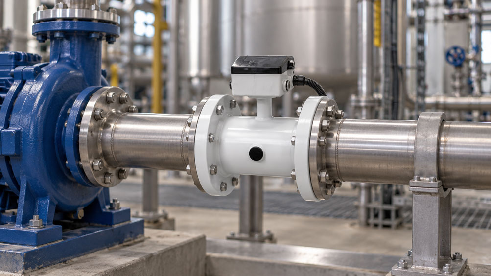
A flowmeter is installed directly downstream of a centrifugal pump in an industrial water pipeline. The pipeline is correctly sized, the measuring instrument has been calibrated and the configuration is correct. Nevertheless, the indicated volumetric flow rate fluctuates more than expected.
Inspection reveals that only a short straight pipe section is available between the pump outlet and the flowmeter. Additionally, a pipe elbow is located immediately downstream of the measuring instrument.
The cause may be a disturbed flow profile. Downstream of a pump, swirl, uneven velocity distributions and hydraulic pulsations may occur. Under unfavorable operating conditions, vapor or gas bubbles can also affect the measurement.
A correctly calibrated flowmeter can only provide reliable process values if its hydraulic installation conditions are also suitable for the measuring principle.
The required distance from the pump is not the same for all instruments. Electromagnetic flowmeters, clamp-on ultrasonic systems and vortex flowmeters respond differently to disturbed flow profiles.
This technical article explains the most important influencing factors and uses a calculation example to show how upstream and downstream straight pipe runs should be considered during measurement point planning.
Table of Contents
- Measurement Task Downstream of a Pump
- Flow Profile and Velocity Distribution
- Swirl and Turbulence Downstream of Pumps
- Identifying Cavitation and Vapor Bubbles
- Air Bubbles and Partially Filled Pipelines
- Determining Upstream Straight Pipe Runs Correctly
- Downstream Straight Pipe Runs and Fittings
- Practical Example: Installation Distances and Flow Velocity
- Influence of Pump Design
- Pipe Elbows, T-Pieces and Valves
- Electromagnetic Flowmeters
- Clamp-On Ultrasonic Flowmeters
- Vortex Flowmeters
- Coriolis Flow Measurement
- Horizontal and Vertical Installation Orientation
- Medium, Temperature and Viscosity
- Nominal Diameter and Flow Velocity
- Measurement Signals and Signal Filtering
- Identifying Typical Measurement Errors
- Testing and Commissioning Procedure
- Solutions for Insufficient Straight Pipe Runs
- Suitable ICS Products
- Conclusion
- Frequently Asked Questions
1. Measurement Task Downstream of a Pump
Flowmeters are installed downstream of pumps to monitor delivery rates, cooling circuits, dosing processes and industrial utility systems, for example.
The installation location should ensure sufficient operating pressure, a completely filled pipeline and flow conditions that are as well-defined as possible.
Whether installation directly at the pump outlet is permissible depends on the requirements of the respective flowmeter.
2. Flow Profile and Velocity Distribution
In a straight pipeline, a characteristic velocity distribution develops depending on the Reynolds number and inlet conditions.
Downstream of pumps, valves or pipe elbows, this distribution can be significantly asymmetrical.
Many flow measurement methods require a sufficiently well-defined flow profile or account for its typical shape during calibration.
If the actual profile deviates significantly from this, systematic measurement errors may occur.
3. Swirl and Turbulence Downstream of Pumps
In swirling flow, the fluid has a rotational velocity component in addition to its axial movement.
Such flow conditions can be caused by pump impellers and unfavorable piping arrangements.
A combination of a pump and a pipe elbow installed immediately downstream can be particularly critical.
The upstream straight pipe run should allow the flow profile to stabilize sufficiently. The actual pipe length required depends on the measuring instrument and the flow disturbance.
4. Identifying Cavitation and Vapor Bubbles
Cavitation occurs when the local liquid pressure falls below the temperature-dependent vapor pressure and vapor bubbles form.
When the pressure subsequently increases, these bubbles may collapse again. This can cause hydraulic disturbances, noise, vibrations and component damage.
Cavitation is particularly relevant at locations with locally low pressure, for example in the suction region or inside a pump.
A flowmeter installed downstream of the pump can be affected by the resulting two-phase flow.
A longer upstream straight pipe run is not a reliable method of eliminating cavitation. The causes must be investigated by evaluating pump design, available NPSH, temperature and pressure conditions.
5. Air Bubbles and Partially Filled Pipelines
Not every gas bubble is caused by cavitation. Air may enter through leaking suction lines or be released from the liquid, for example.
Gas bubbles can particularly affect ultrasonic measurements. Electromagnetic flowmeters also require a sufficiently filled measuring tube for their intended operation.
Installation at the highest point of the pipeline should therefore be avoided for corresponding liquid measurements.
6. Determining Upstream Straight Pipe Runs Correctly
The upstream straight pipe run is the straight section of pipe before the flowmeter in which the flow should stabilize after an upstream disturbance.
The required length is frequently specified as a multiple of the internal pipe diameter D.
For example, 10 × D with an internal pipe diameter of 100 mm corresponds to a straight pipe length of 1,000 mm.
For the Siemens SITRANS FS220, a minimum of 10 × D upstream of the measuring instrument is typically specified. For the MAG 5100 W, Siemens specifies 5 × D as a general installation requirement.
The specific manufacturer instructions are decisive. Longer distances may be necessary depending on the disturbance.
7. Downstream Straight Pipe Runs and Fittings
The pipe section downstream of the measuring instrument can also be important for measurement quality.
Valves, pipe elbows or changes in cross-section located immediately downstream can influence the flow conditions.
For the SITRANS FS220, Siemens typically specifies at least 5 × D downstream straight pipe run, while 3 × D is generally specified for the MAG 5100 W.
These values must not be applied to arbitrary other instruments.
| Installation Condition | Possible Influence | Planning Recommendation |
|---|---|---|
| Pump immediately upstream of the measuring instrument | Swirl, asymmetrical flow profile or pulsation | Check instrument-specific upstream straight pipe requirements |
| Pipe elbow upstream of the sensor | Uneven velocity distribution | Consider the distance from the last relevant flow disturbance |
| Two elbows in different planes | Pronounced three-dimensional flow | Extended upstream straight pipe run may be required |
| Partially closed valve | Strongly asymmetrical flow | Select suitable spacing and valve position |
| Cavitation or air bubbles | Signal disturbances and two-phase flow | Investigate the hydraulic cause and degassing |
| Incompletely filled measuring tube | Invalid or unstable liquid measurement | Ensure suitable piping arrangement and installation orientation |
8. Practical Example: Installation Distances and Flow Velocity
A flowmeter is to be installed downstream of a centrifugal pump in an industrial water pipeline.
The available options are a SITRANS FS220 clamp-on ultrasonic system and an electromagnetic flow measurement system with a MAG 5100 W.
The following geometrical and hydraulic data are freely selected example values.
8.1 Initial Data
- Internal pipe diameter: 100 mm.
- Volumetric flow rate: 30 m³/h.
- Straight pipe section between the last hydraulic disturbance and the measuring instrument: 0.60 m.
- Straight pipe section downstream of the measuring instrument to the next pipe elbow: 0.40 m.
- Typical FS220 requirement: 10 × D upstream, 5 × D downstream.
- General MAG 5100 W requirement: 5 × D upstream, 3 × D downstream.
8.2 Calculating the Pipe Cross-Section
The internal diameter is:
D = 100 mm = 0.100 m
For a circular pipeline:
A = π · D² / 4
A = π · 0.100² / 4
A ≈ 0.007854 m²
8.3 Converting the Volumetric Flow Rate
The specified volumetric flow rate is:
V̇ = 30 m³/h
Converted to seconds:
V̇ = 30 / 3,600
V̇ ≈ 0.008333 m³/s
8.4 Average Flow Velocity
The average velocity is calculated as:
v = V̇ / A
v = 0.008333 / 0.007854
v ≈ 1.06 m/s
This is the flow velocity averaged over the pipe cross-section. The actual local velocity distribution may differ considerably.
8.5 Required Straight Pipe Runs for the SITRANS FS220
For the typical upstream straight pipe run:
LInlet = 10 · 0.100 m
LInlet = 1.00 m
For the downstream straight pipe run:
LOutlet = 5 · 0.100 m
LOutlet = 0.50 m
However, only 0.60 m and 0.40 m are available, respectively.
For this typical installation condition, the following lengths are therefore missing:
0.40 m upstream straight pipe run and 0.10 m downstream straight pipe run.
8.6 Required Straight Pipe Runs for the MAG 5100 W
For the general upstream requirement:
LInlet = 5 · 0.100 m
LInlet = 0.50 m
For the downstream requirement:
LOutlet = 3 · 0.100 m
LOutlet = 0.30 m
The available lengths of 0.60 m and 0.40 m meet these general geometric minimum requirements.
However, this does not yet demonstrate that the complete installation directly downstream of the specific pump will achieve the required measurement accuracy. The actual flow profile and additional manufacturer specifications must also be checked.
8.7 Summary of Results
| Parameter | SITRANS FS220 | MAG 5100 W |
|---|---|---|
| Measuring principle | Clamp-on ultrasonic | Electromagnetic |
| Internal pipe diameter | 100 mm | 100 mm |
| Volumetric flow rate | 30 m³/h | 30 m³/h |
| Average velocity | 1.06 m/s | 1.06 m/s |
| Typical upstream requirement | 10 × D | 5 × D |
| Required upstream straight pipe run | 1.00 m | 0.50 m |
| Available upstream straight pipe run | 0.60 m | 0.60 m |
| Typical downstream requirement | 5 × D | 3 × D |
| Required downstream straight pipe run | 0.50 m | 0.30 m |
| Available downstream straight pipe run | 0.40 m | 0.40 m |
| Geometric assessment | Typical minimum straight pipe runs not met | General minimum straight pipe runs met |
8.8 Interpreting the Result
In this example, the available straight pipe run is too short for the FS220 according to the typical requirements specified. For the MAG 5100 W, however, it initially meets the general minimum requirements.
Electromagnetic measurement also requires a sufficiently conductive liquid, a completely filled measuring tube and correct electrical installation.
A specific percentage measurement error cannot be calculated solely from an insufficient straight pipe run. The error depends on the actual flow disturbance, measuring method and measuring point design.
9. Influence of Pump Design
Centrifugal pumps and positive displacement pumps can produce different flow conditions.
For centrifugal pumps, swirl, operating conditions and flow distribution must be considered in particular.
Positive displacement pumps can cause pronounced time-dependent fluctuations in delivery rate. Multi-pump installations with changing operating conditions should also be considered when planning measurement points.
10. Pipe Elbows, T-Pieces and Valves
A pipe elbow changes the velocity profile. Several elbows arranged in different planes can generate additional swirl components.
Partially closed control valves can cause particularly strong local velocity differences and pressure fluctuations.
The required flow stabilization length should therefore not be determined solely from the pump outlet, but should take all relevant upstream disturbances into account.
11. Electromagnetic Flowmeters
Electromagnetic flowmeters measure the volumetric flow rate of electrically conductive liquids according to Faraday’s principle.
The sensor must be sufficiently filled and requires suitable electrical equipotential bonding with the medium.
The measuring principle does not require mechanical components inside the flow channel to perform the actual measurement.
Nevertheless, unfavorable flow profiles can impair measurement accuracy. The instrument-specific installation conditions remain decisive.
12. Clamp-On Ultrasonic Flowmeters
Clamp-on ultrasonic flowmeters measure liquid flow externally through the pipe wall.
In the transit-time difference method, differences in ultrasonic transit time with and against the flow direction are evaluated.
The system requires correct pipe parameters, suitable sensor positions and sufficiently stable acoustic signal transmission.
Swirl, unfavorable velocity profiles and gas bubbles can impair measurement quality.
For the SITRANS FS220, the specified upstream straight pipe runs and the requirements for mounting position and pipe filling must therefore be considered.
13. Vortex Flowmeters
Vortex flowmeters measure the vortex shedding frequency downstream of a specially designed bluff body.
Under suitable conditions, the vortex frequency is related to the flow velocity.
A strongly disturbed inlet flow profile, pronounced pulsations or significant vibrations can affect the evaluation.
The appropriate upstream straight pipe run must therefore be determined based on the specific instrument configuration and upstream fittings.
14. Coriolis Flow Measurement
Coriolis flowmeters measure mass flow through the dynamic effect of the flowing medium on vibrating measuring tubes.
They frequently do not require the same conventional straight pipe runs as flow-profile-dependent measuring methods.
However, gas bubbles, mechanical vibrations, unfavorable two-phase flow and instrument-specific installation requirements must be considered.
Selection should therefore not be based solely on the shortest possible required straight pipe run.
15. Horizontal and Vertical Installation Orientation
Installation orientation particularly influences pipe filling and possible gas accumulation.
In horizontal pipelines, gas bubbles can accumulate in the upper section. Certain clamp-on systems therefore specify sensor positions offset to the side.
In vertical liquid pipelines, an upward flow direction may be advantageous to support complete pipe filling.
The final orientation depends on the specific instrument and process conditions.
16. Medium, Temperature and Viscosity
Water, glycol mixtures, oils and process liquids have different densities, viscosities and acoustic properties.
These influence both the flow profile and the suitability of certain measuring principles.
For ultrasonic measurements, factors including the speed of sound and pipe wall structure must be considered.
Electromagnetic instruments require sufficient electrical conductivity. Temperature also affects vapor pressure and therefore the possible occurrence of cavitation.
17. Nominal Diameter and Flow Velocity
The nominal pipe diameter alone is insufficient for calculating flow velocity. The actual internal diameter of the flow cross-section is decisive.
When selecting an instrument, minimum and maximum flow rates, velocity, pressure drop and available installation length must be considered.
A larger measuring tube can reduce flow velocity. However, this is not automatically better from a measurement perspective if the velocity falls below the instrument’s favorable operating range.
18. Measurement Signals and Signal Filtering
Depending on their configuration, flowmeters may have current outputs, pulse or frequency outputs and digital communication interfaces.
Measurement filters and damping times can stabilize the indication when the delivery rate is pulsating.
However, strong filtering does not eliminate an unfavorable flow profile, gas bubbles or cavitation.
The actual response time of the complete measurement chain must also be considered for control and monitoring applications.
19. Identifying Typical Measurement Errors
An unusually fluctuating flow reading can result from actual changes in delivery rate or from a disturbed measurement.
For diagnosis, pump speed, valve position, pressure profile and instrument diagnostics should be evaluated together.
For ultrasonic flowmeters, signal quality and acoustic coupling can provide important diagnostic information.
For electromagnetic instruments, pipe filling, conductivity, equipotential bonding and empty pipe diagnostics should be checked in particular.
20. Testing and Commissioning Procedure
The following procedure is recommended for systematic commissioning:
- Record the medium, temperature and pressure conditions.
- Document pump design and operating conditions.
- Determine the volumetric flow range and internal pipe diameter.
- Record the piping arrangement and relevant flow disturbances.
- Select a suitable measuring principle.
- Check the required upstream and downstream straight pipe runs.
- Evaluate pipe filling and possible gas bubbles.
- Install the measuring instrument according to manufacturer instructions.
- Check the measured value, diagnostics and scaling.
- Test and document the measuring point under typical operating conditions.
21. Solutions for Insufficient Straight Pipe Runs
If the existing pipeline does not provide the required installation length, alternative measuring locations should be investigated.
A longer straight pipe section, a modified piping arrangement or a suitable alternative measuring principle may resolve the problem.
Special flow conditioners may be used in certain applications, provided the instrument manufacturer approves the combination.
However, an apparently more stable indication achieved through increased damping does not demonstrate that measurement accuracy has been corrected.
22. Suitable ICS Products
ICS Schneider Messtechnik offers various Siemens flowmeters for industrial pump and pipeline installations.
| Product | Measuring Principle | Important Selection Criteria |
|---|---|---|
| Siemens SITRANS FS220 | Clamp-on ultrasonic | Liquid measurement without contact with the medium; check pipe parameters and upstream straight pipe run |
| Siemens MAG 5100 W | Electromagnetic | Water and wastewater, conductive medium, pipe filling and equipotential bonding |
| Siemens MAG 3100 | Electromagnetic | Industrial liquids, suitable materials and process conditions |
| Siemens MAG 5000 / 6000 | Transmitters for SITRANS FM | Select compatible sensor; consider signals and diagnostic functions |
| Siemens SITRANS FMT020 | Transmitter for compatible electromagnetic flow sensors | Flow, conductivity and empty pipe diagnostics |
| Siemens SITRANS FX300 | Vortex | Liquids, steam and gases; check instrument-specific upstream straight pipe requirements |
22.1 Siemens SITRANS FS220
The SITRANS FS220 is a clamp-on ultrasonic flowmeter for liquids.
It consists of the SITRANS FST020 transmitter and suitable FSS200 clamp-on sensors.
Measurement takes place externally through the pipe wall. Pipe parameters, flow profile, pipe filling and the specified upstream straight pipe runs are important when planning the measuring point.
SITRANS FS220 – Product Information
22.2 Siemens SITRANS FM MAG 5100 W
The MAG 5100 W is an electromagnetic flow sensor for water and wastewater applications.
It is available for suitable nominal pipe sizes from DN 15 to DN 2000 and can be combined with compatible Siemens transmitters.
Important requirements include a completely filled pipeline, suitable equipotential bonding and the specified upstream and downstream straight pipe runs.
MAG 5100 W – Product Information
22.3 Siemens SITRANS FM MAG 3100
The MAG 3100 is an electromagnetic flow sensor for various industrial process liquids.
Depending on the variant, different liners, electrode materials and process connections are available.
It is operated with a compatible MAG transmitter.
MAG 3100 – Product Information
22.4 Siemens MAG 5000 and MAG 6000
The MAG 5000 and MAG 6000 transmitters form an electromagnetic flow measurement system when combined with compatible SITRANS FM flow sensors.
They provide flow readings, totalizers and diagnostic information, among other functions.
MAG 5000 / MAG 6000 – Product Information
22.5 Siemens SITRANS FMT020
The FMT020 is a transmitter for compatible Siemens flow sensors and supports the measurement of flow, flow velocity and electrical conductivity, among other parameters.
Empty pipe monitoring and instrument self-diagnostics are also available.
SITRANS FMT020 – Product Information
22.6 Siemens SITRANS FX300
The SITRANS FX300 is a vortex flowmeter for suitable liquids, steam and gases.
It provides HART communication and corresponding versions with pressure and temperature compensation.
For installation downstream of pumps, the flow profile, possible pulsations and specific upstream straight pipe requirements must be checked in particular.
SITRANS FX300 – Product Information
Additional Flow Measurement Instruments at ICS Schneider Messtechnik
23. Conclusion
Flowmeters installed directly downstream of pumps may be affected by swirl, uneven flow profiles, pulsations and the presence of gas and vapor bubbles.
The required upstream and downstream straight pipe runs depend on the measuring principle used and the specific instrument configuration.
For the SITRANS FS220, for example, typical upstream straight pipe runs of 10 × D and downstream runs of 5 × D are documented. For the MAG 5100 W, the general installation requirements are 5 × D and 3 × D, respectively.
These values do not replace an assessment of the actual pump and piping conditions.
Cavitation must be investigated as a separate hydraulic problem. A longer pipe section does not automatically eliminate its cause.
The decisive factor is therefore not simply the distance from the pump. Reliable flow measurement requires a suitable measuring principle, sufficient straight pipe runs, a completely filled pipeline and an assessment of all relevant flow disturbances.
24. Frequently Asked Questions
24.1 Can a Flowmeter Be Installed Directly Downstream of a Pump?
Only if the instrument-specific installation conditions are met. A suitable straight upstream pipe run is frequently required.
24.2 Why Do Pumps Affect Flow Measurement?
They can cause swirl, uneven velocity profiles and hydraulic pulsations.
24.3 What Does Swirl Mean in a Pipeline?
Swirl describes an additional rotational flow component that influences the local velocity distribution.
24.4 What Is an Upstream Straight Pipe Run?
It is a straight pipe section before the flowmeter that allows the flow profile to stabilize.
24.5 How Long Must the Upstream Straight Pipe Run Be?
This depends on the instrument and upstream disturbances. Manufacturer specifications are decisive.
24.6 What Upstream Straight Pipe Run Does the SITRANS FS220 Require?
Siemens typically specifies at least 10 × the internal pipe diameter upstream and 5 × downstream. Longer distances may be required for certain disturbances.
24.7 What Straight Pipe Runs Does the MAG 5100 W Require?
The Siemens operating manual generally specifies 5 × the internal pipe diameter upstream and 3 × downstream. Different conditions may apply to certain approved applications.
24.8 What Does 10 × D Mean for DN 100?
If the actual internal pipe diameter is 100 mm, this corresponds to 1,000 mm of straight pipe. However, DN 100 alone does not define the exact internal diameter.
24.9 What Is Cavitation?
Cavitation occurs when the local liquid pressure falls below the vapor pressure, causing vapor bubbles to form. These may collapse when the pressure rises again.
24.10 Can Cavitation Disturb a Flowmeter?
Yes. The presence of vapor bubbles and the resulting two-phase flow can affect measurement quality.
24.11 Does a Longer Upstream Straight Pipe Run Prevent Cavitation?
No. The cause must be eliminated by evaluating the hydraulic pressure conditions and pump operating conditions.
24.12 Why Are Air Bubbles Problematic in Ultrasonic Measurements?
They can interfere with the transmission and evaluation of ultrasonic signals.
24.13 Is an Electromagnetic Flowmeter Less Sensitive to Swirl?
Sensitivity differs depending on the measuring principle and design. Electromagnetic instruments must also be installed according to their installation specifications.
24.14 Does a Coriolis Flowmeter Require Straight Pipe Runs?
Frequently not to the same extent as other measuring methods. The specific manufacturer requirements and possible effects of gas bubbles and vibrations remain important.
24.15 Can Increased Signal Damping Correct an Installation Error?
No. Damping can reduce fluctuations but does not eliminate systematic measurement errors caused by an unsuitable flow profile.
24.16 Is a Vertical Pipeline Better?
For liquids, upward flow may help keep the measuring tube completely filled. The suitable installation orientation depends on the instrument.
24.17 What Can Be Done if There Is Insufficient Straight Pipe Length?
Consider a different measuring location, a modified piping arrangement or a suitable alternative measuring method.
24.18 What Information Does ICS Need to Prepare a Quotation?
The required information includes the medium, flow range, internal pipe diameter, pressure, temperature, pump type, piping arrangement, available installation lengths, output signals and required approvals.