


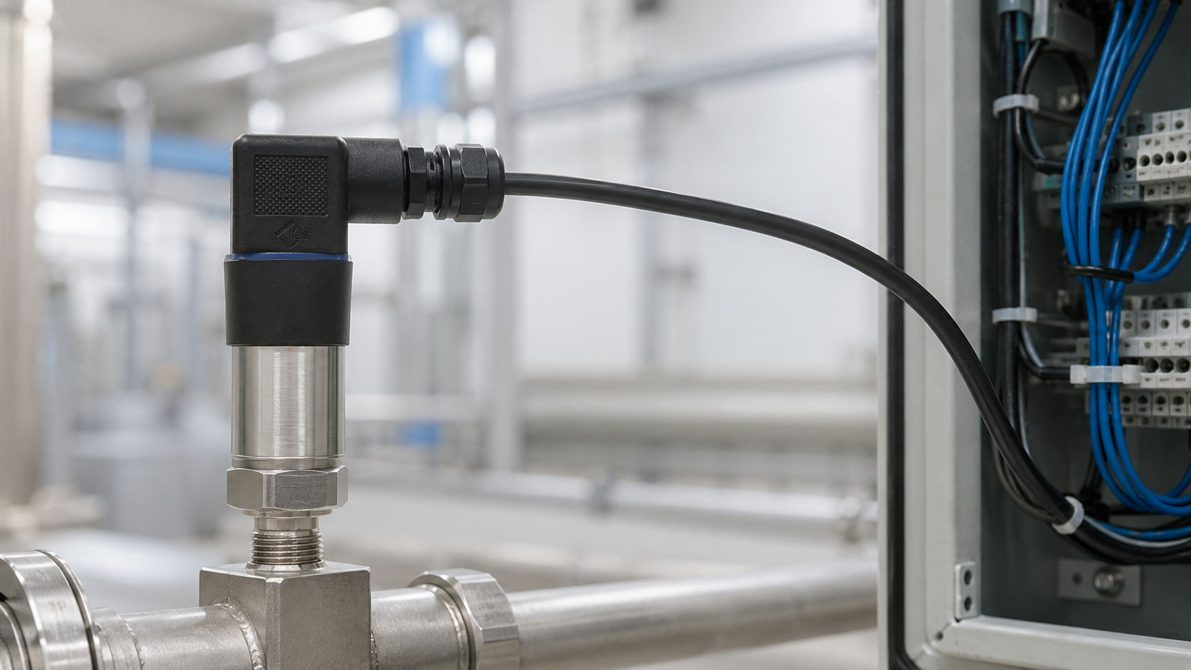
If a 4–20 mA pressure sensor does not provide a signal, a sensor defect is often suspected first. In practice, however, the cause is very often found in the wiring, power supply, current loop, burden or PLC input. Especially with 2-wire transmitters, the complete measuring loop must be considered, not just the sensor itself.
A 4–20 mA signal is generally robust and suitable for industrial use. Nevertheless, failures can occur due to reversed polarity, cable breakage, missing supply voltage, incorrect input card, excessive load resistance or an incorrect measuring method. The difference between 0 mA, an error current such as 3.6 mA and a valid 4 mA signal is also important for troubleshooting.
This article shows how a 4–20 mA pressure sensor can be checked systematically, which typical wiring errors occur and how the sensor, cable, power supply and PLC input can be narrowed down with a multimeter or loop calibrator.
Table of contents
- Basics: How does a 4–20 mA pressure sensor work?
- Understanding 2-wire connection correctly
- No signal: What does that actually mean?
- Checking the supply voltage
- Measuring the current loop correctly
- Taking burden and load resistance into account
- Reversed polarity and incorrect terminals
- Checking cable breakage, wiring faults and shielding
- Incorrect PLC input or incorrect parameterisation
- 0 mA, 3.6 mA or 21 mA: Interpreting fault states correctly
- Checking the signal with a loop calibrator
- Step-by-step troubleshooting
- Table: Fault pattern, possible cause and test step
- Practical example: Pressure sensor without signal at the PLC
- Which measuring instruments are suitable?
- Conclusion: Check the measuring loop first, then replace the sensor
- FAQ: Frequently asked questions about 4–20 mA pressure sensors without signal
Basics: How does a 4–20 mA pressure sensor work?
A 4–20 mA pressure sensor converts the measured pressure into an analogue current signal. 4 mA typically represents the lower measuring range limit and 20 mA the upper measuring range limit. For example, with a 0…10 bar pressure sensor, this means: 4 mA at 0 bar and 20 mA at 10 bar.
The advantage of a current signal is that it is less sensitive to voltage drops over long cables. As long as the supply voltage and permissible burden are sufficient, the current in the loop can be clearly evaluated.
A valid measuring signal usually does not start at 0 mA. This is important for diagnostics. 0 mA usually means there is no active current loop, for example due to missing supply, cable breakage, incorrect wiring or a defective output. 4 mA, on the other hand, is a valid measured value at the start of the measuring range.
For troubleshooting, it must therefore always be checked whether no current is actually flowing or whether the sensor is outputting a valid lower measured value.
Understanding 2-wire connection correctly
Many industrial pressure transmitters with a 4–20 mA output are designed as 2-wire devices. This means that the supply voltage and measuring signal run through the same two wires. The sensor regulates the current in the loop according to the measured pressure.
The typical setup consists of power supply, sensor, cable, burden or PLC input and return line. All elements are part of one current loop. If this loop is interrupted at any point, no signal current flows.
A common misconception is to treat the sensor like a 3-wire device. With a 2-wire transmitter, there is no separate signal output against ground; instead, the current flow through the entire loop is the signal.
For this reason, the measuring instrument must be connected in series into the loop for current measurement. A parallel measurement as used for voltage does not provide the correct result here.
No signal: What does that actually mean?
The statement “no signal” can mean different things. It may mean that 0 mA is actually flowing. However, it may also mean that the PLC displays 0 bar even though the sensor is delivering 4 mA. Or the input may be incorrectly parameterised and may not interpret the current value correctly.
Therefore, the first step should be to clarify exactly what is being observed: Does the PLC show an error? Is 0 mA measured? Is there voltage at the sensor? Is there a fixed current value that does not change when pressure changes? Or is a value outside the expected range displayed?
A true 0 mA value often indicates an interrupted loop, missing supply voltage, reversed polarity, cable breakage or a defective sensor. A value around 3.6 mA, on the other hand, may be a defined fault state. A value of 4 mA can be a valid measured value if the sensor is at the start of its measuring range.
The exact interpretation depends on the sensor, the output signal and the configuration of the evaluation system.
Checking the supply voltage
One of the first checks is the supply voltage. A 4–20 mA pressure sensor requires sufficient voltage to drive the measuring current through the sensor, cable and burden. Typical industrial supplies are often 24 V DC.
It is important not only to check the voltage at the power supply unit, but preferably also at the sensor or in the measuring loop. Due to cable losses, incorrect terminals, fuses, isolating amplifiers or input modules, the voltage at the sensor may be missing or too low.
If there is no supply voltage at the sensor, the sensor cannot deliver a valid 4–20 mA signal. In this case, the power supply should be checked backwards: power supply unit, fuse, terminals, cable, connectors and input card.
If supply voltage is present but no current is flowing, the loop must be checked further. Possible causes then include reversed polarity, interruption, defective sensor, excessive burden or incorrect connection.
Measuring the current loop correctly
The 4–20 mA signal is measured as current. For this purpose, the multimeter, process calibrator or a suitable loop calibrator must be connected in series into the current loop. The measuring instrument is therefore not connected in parallel to the sensor, but directly inserted into the current path.
A common error is selecting the wrong measuring mode on the multimeter. If voltage mode is accidentally used, the actual loop current is not measured. If the current range is selected incorrectly or the test leads are plugged into the wrong socket, no meaningful measured value can be obtained either.
During current measurement, the internal fuse of the multimeter must also be intact. If the current measurement fuse has blown, the device may show no current even though the current loop is basically functioning.
For service work, a loop calibrator is often much more convenient than a simple multimeter. Devices such as the UPS4E loop calibrator can measure and simulate 4–20 mA signals and, depending on the application, be used to check the measuring chain. This makes it easier to distinguish whether the fault is located at the pressure sensor, the cable, the power supply or the PLC input.
Taking burden and load resistance into account
The burden is the electrical resistance against which the sensor must drive the loop current. This includes the input resistance of the PLC, cable resistance, isolating amplifiers, display instruments and other components connected in series.
If the burden is too high, the supply voltage is no longer sufficient to reliably drive 20 mA. The signal may then remain too low, drop out at higher pressure values or become implausible.
Especially with long cables, several devices in series, additional displays or isolating amplifiers, it should be checked whether the permissible total burden of the sensor is being observed. The maximum permissible burden depends on the supply voltage and sensor data.
A typical fault pattern is that the sensor appears to work at low values, but no longer reaches 20 mA at higher pressure. In this case, the burden should be checked specifically.
Reversed polarity and incorrect terminals
Reversed polarity is a simple but common cause. If plus and minus are swapped, the sensor will not work or will not deliver a correct signal, depending on the design. Some modern sensors have reverse polarity protection, but no valid measuring signal is still generated.
Incorrect terminals at the connector or PLC can also cause failures. Especially with M12 connectors, angled connectors or different connection diagrams, the data sheet or wiring diagram must be checked.
Another error is confusing 2-wire, 3-wire and 4-wire connections. A sensor with 4–20 mA in 2-wire technology is connected differently from an active output with a separate supply.
For unknown sensors, wiring should therefore not be done based on cable colour alone. The pin assignment, wiring diagram and output type of the specific device are decisive.
Checking cable breakage, wiring faults and shielding
A cable break or poor contact interrupts the current loop. No current then flows, and the evaluation system shows 0 mA, an error or a substitute value. Such faults occur particularly often on moving cables, connectors, cable glands or machine connections.
Contact resistance at terminals, loose screw terminals, corroded contacts or damaged connectors can also affect the signal. The fault does not have to occur permanently. With vibration or movement, the signal can fail sporadically.
Continuity measurement, visual inspection, wiggle testing, voltage measurement under load and current measurement at different points in the loop can be helpful for checking. It is important to assess the system safely beforehand and only use suitable measuring methods.
Shielding is also important for analogue signals. Missing or incorrectly connected shielding usually does not lead to 0 mA, but it can cause interference, fluctuating values or unstable signals.
Incorrect PLC input or incorrect parameterisation
Not every analogue input is automatically suitable for 4–20 mA. Some inputs are parameterised for voltage signals such as 0–10 V or require a different terminal assignment for current measurement. If the sensor is connected to the wrong input, the PLC cannot display a correct signal.
The PLC parameterisation is also decisive. The input must be set to 4–20 mA. In addition, the scaling must match the measuring range of the pressure sensor. Otherwise, the controller will display incorrect pressure values even though the current is correct.
Another point is whether the input is active or passive. With passive 2-wire transmitters, the loop must be supplied correctly. Some input cards provide the supply, while others require an external power supply.
For troubleshooting, it is helpful to measure the current directly before the PLC input or to feed in a known signal with a loop calibrator. If the PLC then displays correctly, the fault is more likely to be located at the sensor or in the cable.
0 mA, 3.6 mA or 21 mA: Interpreting fault states correctly
With 4–20 mA signals, 0 mA is usually not a valid measured value. 0 mA usually indicates an interrupted current loop, missing supply or a serious fault. 4 mA, on the other hand, is the normal start of the measuring range.
Many sensors can output defined fault currents in the event of an error, for example below 4 mA or above 20 mA. Common values are, for example, around 3.6 mA or above 21 mA. The exact meaning depends on the sensor and its configuration.
A current value below 4 mA can therefore indicate a sensor fault, underrange or fault state. A value above 20 mA can indicate overrange, sensor fault or a configured fault output.
It is important to check the fault current limits in the data sheet or parameterisation. Without this information, a value outside the measuring range can easily be misinterpreted.
Checking the signal with a loop calibrator
A loop calibrator is a very helpful tool for troubleshooting 4–20 mA signals. Depending on the version, it can measure loop current, simulate a 4–20 mA signal and sometimes also supply the loop with voltage.
This allows the measuring chain to be separated in a targeted way. If the sensor is disconnected and a defined current of 4 mA, 12 mA or 20 mA is fed into the PLC input, it can be checked whether the input, scaling and display are working correctly.
Conversely, the sensor can be checked with the loop calibrator by directly measuring the current supplied by the sensor. If the current changes correctly when the pressure changes, the sensor is probably working correctly.
The major advantage is clear fault isolation: sensor, cable, power supply and evaluation can be checked separately step by step.
Step-by-step troubleshooting
The following procedure helps narrow down the cause systematically. Depending on the system, sensor and safety requirements, manufacturer specifications and company requirements must be observed.
- Clarify the fault pattern: Does the PLC show 0, error, overrange or a fixed value?
- Check the connection diagram: Check sensor type, pin assignment, 2-wire/3-wire connection and output signal.
- Check supply: Measure voltage at the power supply unit and, if possible, at the sensor or in the loop.
- Measure current: Measure loop current in series or use a loop calibrator.
- Exclude reversed polarity: Check plus, minus, terminals and connector assignment.
- Check cable: Check cable breakage, loose terminals, connectors, shielding and continuity.
- Check burden: Consider load resistors, input resistance, isolating amplifier and cable length.
- Check PLC input: Check input type, parameterisation, scaling and active/passive supply.
- Simulate signal: Feed in 4 mA, 12 mA and 20 mA with a loop calibrator and check the display.
- Check sensor separately: Test sensor with known supply and pressure change.
- Document result: Note measuring points, currents, voltages and configuration.
Table: Fault pattern, possible cause and test step
| Fault pattern | Possible cause | Next test step |
|---|---|---|
| 0 mA measured | No supply, cable break, reversed polarity, open loop or defective sensor | Check supply, wiring and loop continuity |
| PLC shows 0 bar, current is 4 mA | 4 mA corresponds to measuring range start or scaling is incorrect | Check PLC scaling and current pressure |
| Current remains constant | No pressure change, sensor blocked, incorrect connection or sensor fault | Generate pressure change and measure sensor directly |
| Signal drops out at higher pressure | Burden too high or supply voltage too low | Check total burden and voltage under load |
| PLC shows incorrect pressure value | Incorrect scaling or wrong input type | Simulate 4/12/20 mA and compare PLC display |
| Signal fluctuates strongly | Shielding, EMC, loose terminals, contact problem or unstable supply | Check terminals, shielding, cable and supply |
| Current is below 4 mA | Fault current, underrange, sensor fault or supply too low | Check data sheet and test sensor separately |
| Current is above 20 mA | Overrange, fault current or incorrect measuring range | Check pressure range, fault output and scaling |
Practical example: Pressure sensor without signal at the PLC
After replacing a pressure sensor, the PLC no longer displays a pressure value. The sensor is initially suspected of being defective because 0 bar is shown on the operator panel. The system is stopped, and the fault needs to be narrowed down quickly.
First, the wiring is compared with the sensor connection diagram. This shows that it is a 2-wire transmitter. The supply voltage in the loop is then checked. 24 V DC is present at the power supply unit, but there is no sufficient voltage at the sensor.
Further testing shows that the sensor was connected to an analogue input that was parameterised for a 0–10 V voltage signal. In addition, the current loop was not closed correctly. After rewiring to the correct 4–20 mA input and adapting the PLC parameterisation, the measurement is repeated.
The loop current is now around 4 mA in the depressurised state and increases when pressure is applied. The sensor is therefore not defective. The cause was incorrect input wiring and parameterisation.
Which measuring instruments are suitable?
Multimeters, process calibrators and loop calibrators are suitable for troubleshooting 4–20 mA pressure sensors. A multimeter can check supply voltage, continuity and loop current. It is important that the current range is used correctly.
A loop calibrator is particularly practical because it can measure and simulate 4–20 mA signals. This makes it quick to check whether the PLC displays the correct value or whether the sensor outputs correctly.
For service work, devices that can both measure and source current are helpful. In more complex systems, isolating amplifiers, supply units, test terminals and documentation functions may also be relevant.
The choice of measuring instrument depends on whether only a simple signal is to be checked or a complete measuring chain consisting of sensor, cable, supply, isolating amplifier and PLC is to be examined.
Conclusion: Check the measuring loop first, then replace the sensor
If a 4–20 mA pressure sensor does not provide a signal, the sensor is not automatically defective. The causes are often found in wiring, supply voltage, burden, cable, reversed polarity, PLC input or parameterisation.
Systematic testing saves time and avoids unnecessary sensor replacement. The decisive factor is to consider the complete current loop: supply, sensor, cable, load resistance, evaluation and scaling.
With a multimeter and loop calibrator, it can be quickly narrowed down whether the sensor is providing a correct signal, whether the PLC is evaluating it correctly or whether the loop is interrupted. Only once supply, wiring and evaluation have been ruled out should a sensor defect be considered likely.
FAQ: Frequently asked questions about 4–20 mA pressure sensors without signal
Why does my 4–20 mA pressure sensor not provide a signal?
Common causes include missing supply voltage, cable breakage, reversed polarity, open current loop, incorrect PLC input, excessive burden or a defective sensor.
How do you check a 4–20 mA signal?
The loop current is measured in series. Alternatively, a loop calibrator can be used to measure the current or simulate a defined signal.
What does 0 mA mean with a 4–20 mA sensor?
0 mA is normally not a valid measured value. It usually indicates an interrupted loop, missing supply, reversed polarity or a serious fault.
Is 4 mA an error?
No. 4 mA is normally the valid start of the measuring range. For a 0…10 bar pressure sensor, for example, 4 mA corresponds to 0 bar.
What does a current value below 4 mA mean?
A value below 4 mA can be a defined fault current, underrange, sensor fault or a problem with the supply. The exact meaning can be found in the data sheet or parameterisation.
What is the burden in a 4–20 mA signal?
The burden is the total resistance in the current loop. This includes PLC input, cables, isolating amplifiers and other devices connected in series.
What happens if the burden is too high?
If the burden is too high, the supply voltage may not be sufficient to drive the required current. The signal can then remain too low or drop out.
How do you identify a pressure sensor with reversed polarity?
With reversed polarity, the sensor usually does not provide a signal. Plus, minus and pin assignment must be compared with the sensor connection diagram.
Can an incorrect PLC input be the cause?
Yes. If the input is set to 0–10 V instead of 4–20 mA, or if a different terminal assignment is required, the signal will not be evaluated correctly.
How do you check the PLC evaluation?
A loop calibrator can be used to feed in a defined current of 4 mA, 12 mA or 20 mA. The PLC display must then respond according to the scaled pressure value.
What is the difference between a 2-wire and 3-wire pressure sensor?
With a 2-wire sensor, supply and signal run through the same two wires. With a 3-wire sensor, there are typically separate wires for supply and signal output.
When should the sensor be replaced?
Only once supply, wiring, burden, cable, PLC input and parameterisation have been checked and the sensor still does not provide a correct signal is a sensor defect likely.