


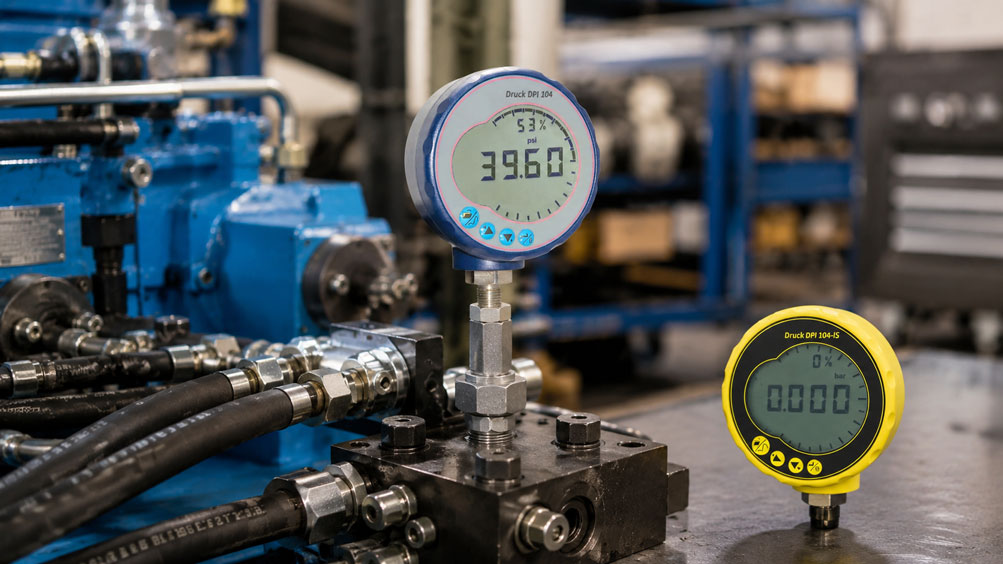
If a hydraulic system no longer reaches full force, works too slowly or reacts unevenly, hydraulic pressure is one of the most important values to check. Pressure that is too low can indicate a worn pump, an incorrectly adjusted pressure relief valve, internal leakage, clogged filters, defective valves or problems in the hydraulic circuit.
With a digital pressure gauge, the pressure in a hydraulic system can be checked and documented precisely. Compared with a simple analogue pressure gauge, many digital pressure gauges offer better readability, higher accuracy, min/max memory, peak value recording or leak test functions. This is particularly helpful in service and maintenance because pressure peaks, working pressure and maximum pressure can be evaluated in a targeted way.
This article shows step by step how hydraulic pressure can be checked safely, what must be considered regarding measuring range, Minimess connection, pressure peaks and safety valves, and how typical causes of faults can be narrowed down.
Table of contents
- Why hydraulic pressure is so important
- Why a digital pressure gauge is useful for hydraulic testing
- Selecting a suitable measuring range
- Connecting a hydraulic pressure gauge correctly
- Using a Minimess connection for service and maintenance
- Taking pressure peaks and overload into account
- Step-by-step guide to hydraulic pressure testing
- Checking and evaluating working pressure
- Storing maximum pressure and peak values
- Checking the pressure relief valve and safety valve
- Hydraulic pressure too low: Possible causes
- Typical measuring errors during hydraulic pressure testing
- Table: Measurement pattern, possible cause and test step
- Practical example: Machine no longer reaches full force
- Which digital pressure gauge is suitable?
- Conclusion: Check hydraulic pressure systematically instead of guessing
- FAQ: Frequently asked questions about hydraulic pressure testing
Why hydraulic pressure is so important
Hydraulic systems transmit force through pressure. If a machine no longer delivers the desired force, a cylinder moves more slowly or a press no longer reaches its target value, hydraulic pressure is one of the first values that should be checked.
The pressure shows whether the pump, valves, lines, consumers and pressure limitation are basically working together. Pressure that is too low can indicate that the pump no longer delivers enough flow, that a valve is leaking internally, that the pressure relief valve opens too early or that flow is being lost somewhere in the system.
Excessive pressure is also critical. It can overload components, damage seals, endanger hoses or unnecessarily stress safety valves. This is why not only a minimum pressure is important, but also the control of the permissible maximum pressure.
Pressure measurement is therefore a central part of hydraulic diagnostics. It helps distinguish mechanical problems, hydraulic faults and incorrect settings from one another.
Why a digital pressure gauge is useful for hydraulic testing
A digital pressure gauge displays pressure digitally and, depending on the version, offers additional functions such as min/max memory, peak value recording, tare function, different pressure units, data recording or leak test function. This is particularly practical for hydraulic testing.
With an analogue pressure gauge, fast pressure peaks can easily be missed. A digital pressure gauge with maximum value memory, however, can record the highest pressure reached during a working cycle. This helps, for example, when checking pumps, pressure relief valves or load peaks.
Readability is another advantage. In machines, tight installation spaces or changing light conditions, a digital display is often easier to read than a scale. In addition, the measurement can be documented more accurately.
However, it is important that the digital pressure gauge is suitable for hydraulic applications. Measuring range, overload resistance, process connection, sealing material, media compatibility and dynamic pressure load must match the system.
Selecting a suitable measuring range
The measuring range of the digital pressure gauge must match the expected hydraulic pressure. If the measuring range is too low, the device can be damaged by overpressure. If the measuring range is much too high, resolution suffers and small pressure changes are harder to detect.
As a guideline, the normal working pressure of the system should be known. Possible pressure peaks must also be taken into account. In hydraulic systems, significantly higher pressures than during normal operation can briefly occur when valves switch, when a cylinder reaches its end stop or during load changes.
A digital pressure gauge should therefore not only cover the operating pressure, but also have sufficient safety reserve. The permissible overload of the device and the maximum system pressure must be observed.
Example: If a system operates with a working pressure of 180 bar, a measuring range up to 250 bar or 400 bar may be useful, depending on pressure peaks, accuracy requirement and safety reserve. The specific measuring range must match the respective system.
Connecting a hydraulic pressure gauge correctly
The pressure gauge connection must fit mechanically and hydraulically. Thread type, seal, pressure rating, installation situation and measuring point are decisive. Measuring connections, adapters or Minimess couplings are often used to connect the digital pressure gauge safely and quickly.
Before connection, it must be checked whether the measuring point can be depressurised or whether a measuring connection is designed for connection under pressure. Hydraulic systems can store very high pressures. Improper loosening of fittings can be dangerous.
The sealing surface and thread should be clean and undamaged. Incorrect threads, unsuitable adapters or damaged seals can cause leaks or dangerous pressure discharge.
After connection, the measuring point should be pressurised slowly. Leaks, unusual noises and secure positioning of the pressure gauge should be checked.
Using a Minimess connection for service and maintenance
Minimess connections are very common in hydraulic systems. They allow quick pressure testing without opening the main line. The digital pressure gauge can be connected to the measuring port using a suitable measuring hose.
The advantage is simple and clean service testing. The measuring point is defined, the connection is intended for pressure measurements and the measuring instrument can be positioned flexibly. This is particularly helpful on machines, mobile systems, presses, power units or hydraulic blocks.
It is important that the measuring hose, coupling and digital pressure gauge are suitable for the maximum pressure. The condition of the measuring hose must also be checked. Damaged, kinked or aged hoses must not be used.
During measurement, the hose should be routed so that it cannot be trapped, driven over, kinked or endangered by moving machine parts.
Taking pressure peaks and overload into account
Hydraulic systems can be very dynamic. When valves switch, when a cylinder stops abruptly, during load changes or when moving against an end stop, brief pressure peaks can occur. These peaks are often significantly higher than the normal working pressure.
A digital pressure gauge with maximum value memory can record such peaks, provided that the measuring rate and device are suitable for this. This is important because pressure peaks stress components and can cause long-term damage.
If very fast pressure peaks are expected, a normal pressure gauge may not be sufficient. In that case, a fast pressure sensor with data logger or a suitable measuring system may be required.
Depending on the application, restrictors, pressure snubbers or suitable adapters can be used to protect the measuring instrument. However, it must be noted that strong damping can also falsify or hide fast events.
Step-by-step guide to hydraulic pressure testing
The following procedure serves as general guidance. Depending on the machine, pressure level, medium and safety requirements, manufacturer specifications and company regulations must be observed.
- Check documentation: Check target values, maximum permissible pressure, measuring points and hydraulic diagram.
- Select measuring instrument: Choose a digital pressure gauge with suitable measuring range, accuracy, connection and overload resistance.
- Define measuring point: Select a suitable measuring point, for example pump outlet, valve block, consumer line or Minimess connection.
- Secure the system: Bring the machine into a safe state and consider movements, loads and stored pressure energy.
- Connect pressure gauge: Connect measuring hose, adapter or Minimess coupling correctly and leak-tight.
- Build up pressure slowly: Start the system and observe the pressure build-up in a controlled manner.
- Measure working pressure: Record the pressure in the normal operating condition and compare it with the target value.
- Store maximum pressure: Use the min/max function if required and run through the working cycle.
- Check pressure limitation: Check the safety or pressure relief valve only according to the approved procedure.
- Document measured values: Note measuring point, operating condition, pressure values and abnormalities.
- Release pressure: Safely depressurise the system before removing the measuring hose or adapter.
Checking and evaluating working pressure
Working pressure is the pressure present during normal operation of a hydraulic system. It depends on load, valve position, pump output, cylinder area, process condition and machine function. Therefore, pressure must always be measured in the appropriate operating condition.
A measured value at idle is not automatically meaningful. Many hydraulic systems only build up the relevant working pressure under load or during a specific movement. It should therefore be clear when and where the measurement must be taken.
The measured pressure is compared with the target value from the hydraulic diagram, machine documentation or service specification. Deviations should not be considered only as a number, but in connection with machine behaviour, noise, temperature, speed and force.
If the working pressure is too low although the machine requires load, the cause must be narrowed down. If the pressure is too high, it must be checked whether a valve is blocked, a consumer is stuck or the pressure limitation is incorrectly set.
Storing maximum pressure and peak values
Many faults in hydraulic systems do not occur permanently, but only during certain movements or load changes. This is why the maximum value function of a digital pressure gauge is very helpful.
With the min/max function, it can be checked which highest pressure was reached during a working cycle. This is relevant, for example, for presses, lifting systems, pumps, clamping devices or machines with changing loads.
If the maximum pressure is significantly above the expected range, pressure peaks, incorrectly adjusted valves, blocked lines or mechanical end stops may be the cause. If the maximum pressure is not reached, the pump may be worn, the pressure relief valve may open too early or internal leakage may be present.
It is important to always document the maximum value together with the operating condition. A maximum pressure without specifying the measuring point and working cycle is of limited value later.
Checking the pressure relief valve and safety valve
The pressure relief valve protects the hydraulic system from excessive pressure. It opens when the set limit pressure is reached and diverts oil back to the tank or into a relief path. If this valve is incorrectly adjusted or not working properly, the system may either fail to build enough force or reach dangerously high pressure.
If the valve opens too early, the machine does not reach the required working pressure. If it opens too late or not at all, the pump, lines, hoses, cylinders and seals can be overloaded.
The pressure relief valve may only be checked according to manufacturer specifications and with a suitable measuring instrument. The permissible maximum pressure and the conditions under which the valve may be tested must be known.
A digital pressure gauge helps detect and document the response pressure of the valve. Changes to safety or pressure relief devices should only be carried out by qualified personnel.
Hydraulic pressure too low: Possible causes
Hydraulic pressure that is too low can have many causes. A common cause is a worn or damaged pump. If the pump no longer delivers sufficient flow or pressure, the system no longer reaches the required force.
Internal leakage can also reduce pressure. Oil then flows past sealing points inside valves, cylinders or pumps. Leakage is not always visible externally, but pressure performance is still lost.
An incorrectly adjusted or defective pressure relief valve can also cause the pressure to remain too low. The valve then opens too early and prevents the required pressure build-up.
Other possible causes include clogged filters, low oil level, air in the system, incorrect oil viscosity, defective valves, worn seals, incorrect pump rotation direction or problems with the pump drive.
Typical measuring errors during hydraulic pressure testing
A common error is choosing an unsuitable measuring range. If the pressure gauge is rated too low, it can be damaged by pressure peaks. If it is rated much too high, small deviations are harder to detect.
Another error is measuring at the wrong point. The pressure at the pump outlet is not always identical to the pressure at the consumer. Pressure losses, valves, restrictors and line routes can cause different measuring points to provide different information.
The operating condition is also decisive. A measurement without load may be unremarkable, even though the pressure collapses under load. Conversely, pressure peaks may only occur during certain movements.
Incorrect adapters, damaged measuring hoses, air in the measuring hose, leaking connections or strong damping can also falsify the measurement.
Table: Measurement pattern, possible cause and test step
| Measurement pattern | Possible cause | Next test step |
|---|---|---|
| Working pressure too low | Pump worn, pressure relief valve opens too early, internal leakage | Check pump pressure, valve setting and consumer |
| Pressure does not rise | Pump not delivering, valve open, oil level too low or incorrect rotation direction | Check oil level, pump drive, valve position and suction side |
| Pressure drops under load | Internal leakage, pump too weak, filter clogged or air in the system | Repeat load condition and document pressure curve |
| Maximum pressure is not reached | Pressure relief valve incorrectly set or pump worn | Check response pressure and pump performance |
| Pressure peaks very high | Valve switching, end stop, load change or missing damping | Store maximum value and analyse switching processes |
| Pressure fluctuates strongly | Air in the system, pump pulsation, unstable valve or changing load | Check venting, oil condition, pump and valves |
| Pressure gauge shows sluggish values | Damping too strong, measuring hose clogged or air in the connection | Check measuring setup and connection |
| Leakage at measuring connection | Incorrect adapter, damaged seal or thread problem | Depressurise connection and check sealing point |
Practical example: Machine no longer reaches full force
A hydraulic machine no longer reaches full pressing force. The operator notices that the working cycle takes longer and that the workpiece is no longer processed reliably. At first, no obvious mechanical damage is visible.
A digital pressure gauge is connected to the hydraulic block via a Minimess connection. First, the pressure is checked at idle. The value appears unremarkable. The pressure is then measured during the actual working cycle under load.
It becomes clear that the pressure remains significantly below the target value at the load point. The maximum value function confirms that the required maximum pressure is not reached. The pressure relief valve is then checked. It opens earlier than intended.
After professional inspection and adjustment of the valve, the working cycle is performed again. The pressure once again reaches the target range and the machine delivers the required force. The pump is also checked to rule out existing wear.
The example shows: Only pressure measurement under real load provides a reliable statement. A visual inspection or idle measurement alone would not have shown the cause reliably.
Which digital pressure gauge is suitable?
For hydraulic testing, a digital pressure gauge with a suitable pressure range, sufficient accuracy, robust design and suitable process connection should be used. Overload resistance, good readability and simple operation are also important.
For service work, functions such as min/max memory, tare function, switchable pressure units and, if necessary, data logging are helpful. In dynamic hydraulic systems, it should be checked whether the measuring rate of the device is sufficient for the expected pressure changes.
The accessories must also be suitable. Measuring hoses, Minimess couplings, adapters and seals must be suitable for the maximum pressure and the hydraulic medium. A high-quality digital pressure gauge is of little use if the measuring hose does not match the application.
For very fast pressure peaks or detailed fault analysis, a pressure sensor with data logger or a specialised hydraulic measuring system may be useful.
Conclusion: Check hydraulic pressure systematically instead of guessing
If a hydraulic system no longer reaches full force, works slowly or reacts unusually, the hydraulic pressure should be checked systematically. A digital pressure gauge helps make working pressure, maximum pressure and pressure curve visible.
The correct measuring range, a safe connection, the suitable measuring point and measurement in the correct operating condition are decisive. A careful procedure is especially important with pressure peaks, load changes and safety valves.
Pressure measurement alone does not replace a complete diagnosis, but it provides a central indication. In combination with the hydraulic diagram, machine behaviour and further tests, it can quickly be narrowed down whether the pump, valve, consumer, pressure limitation or measuring setup is the cause.
FAQ: Frequently asked questions about hydraulic pressure testing
How do you check hydraulic pressure?
Hydraulic pressure is measured at a designated measuring point using a suitable pressure gauge or digital pressure gauge. A Minimess connection is often used. The correct measuring range, safe connection and measurement in the correct operating condition are important.
Where do you connect a hydraulic pressure gauge?
The pressure gauge is connected at a suitable measuring point, for example at the pump outlet, valve block, consumer line or Minimess connection. The correct measuring point depends on the question being investigated.
Why is a digital pressure gauge better than a simple pressure gauge?
A digital pressure gauge often offers better readability, higher accuracy, min/max memory, unit switching and sometimes data recording. This allows working pressure and pressure peaks to be documented more effectively.
Which measuring range should the pressure gauge have?
The measuring range must safely cover the expected working pressure and possible pressure peaks. At the same time, it should not be selected unnecessarily high so that resolution remains sufficient.
What is a Minimess connection?
A Minimess connection is a service measuring port in hydraulic systems. A pressure gauge can be connected via a suitable measuring hose without opening the main line.
What does it mean if hydraulic pressure is too low?
Low pressure can indicate a worn pump, internal leakage, an incorrectly adjusted pressure relief valve, air in the system, low oil level or clogged filters.
Why does the pressure drop under load?
If the pressure only drops under load, internal leakage, pump wear, a pressure relief valve opening too early or a problem in the consumer may be present.
How can pressure peaks be detected?
Pressure peaks can be detected with a digital pressure gauge with maximum value memory or with a fast pressure sensor and data logger. An analogue pressure gauge often does not reliably show short peaks.
Can the pressure relief valve simply be adjusted?
No. Pressure relief valves and safety valves may only be checked or adjusted according to manufacturer specifications and by qualified personnel. Incorrect settings can be dangerous.
Why is idle measurement often not sufficient?
Many hydraulic faults only occur under load. At idle, the pressure may appear normal, even though the system does not reach the required pressure during the actual working process.
Which safety rules apply during hydraulic pressure measurements?
Hydraulic systems can store very high pressures. Measuring hoses, adapters and pressure gauges must be suitable. Connections must be made safely and professionally. Before loosening connections, the pressure must be released.
Which measuring instrument is suitable for service and maintenance?
A robust digital pressure gauge with a suitable pressure range, sufficient accuracy, overload resistance, min/max function and suitable accessories such as measuring hose and Minimess coupling is suitable.