


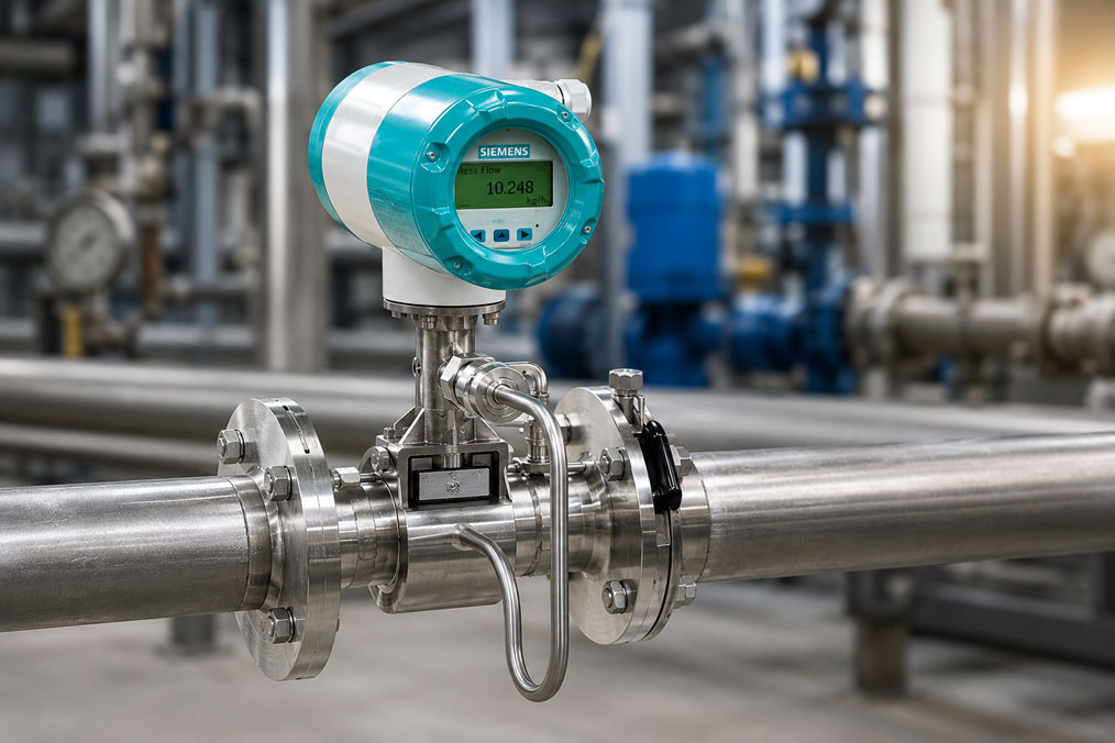
When a vortex flowmeter shows fluctuating values, the cause is often first suspected in the measuring instrument itself. In many cases, however, the problem is not the device, but the flow, the installation situation or the process control. Especially with steam, gases, compressed air, cooling water or process media, pulsating flow, unfavorable pipe routing, vibrations or flow velocities that are too low can lead to unstable measured values.
Vortex flowmeters work reliably when stable vortex shedding forms in the measuring tube. This exact requirement can be disturbed by pumps, compressors, control valves, pipe bends, reducers, pressure and temperature fluctuations or an unfavorable measuring point. The device then displays values, but they appear jumpy, fluctuating or not reproducible.
This article explains why vortex measured values can fluctuate, how to distinguish between real process pulsation and an unsuitable measuring point, and what role minimum flow, vibration, damping, parameterization, diagnostics and signal testing play. The goal is not to simply “smooth out” individual values, but to find the actual cause of the fluctuation.
Table of contents
- Basics: Why a vortex flowmeter needs stable flow
- Fluctuating values: Measurement error or real process condition?
- Process pulsation caused by pumps, compressors and valves
- Wrong measuring point: Pipe routing, inlet section and disturbances
- Flow too low: Why vortex measurements can become unstable at the lower end
- Vibrations and mechanical influences
- Steam flow: Consider pressure, temperature and operating condition
- Using parameterization, damping and diagnostics correctly
- Checking output signal and 4–20 mA
- Table: Typical causes of fluctuating vortex values
- Practical example: Fluctuating steam flow downstream of a control valve
- Table: Testing approach for troubleshooting
- Which measuring instruments / products are suitable?
- Conclusion: Fluctuating vortex values are often an indication of the process
- FAQ: Frequently asked questions about fluctuating vortex flowmeters
Basics: Why a vortex flowmeter needs stable flow
A vortex flowmeter uses vortex shedding behind a bluff body in the measuring tube. When a medium flows past this body at sufficient velocity, alternating vortices are generated. The frequency of these vortices is related to the flow velocity and therefore to the volume flow.
For this measuring principle to work reliably, the flow must be sufficiently uniform and fast enough. The flowmeter needs a usable vortex signal. If the flow is heavily disturbed, pulsating, turbulent or too slow, the signal can become unstable. The device is then not necessarily measuring incorrectly; rather, it is not receiving a clean flow profile.
The installation situation is particularly important. Directly downstream of pumps, compressors, control valves, pipe bends, T-pieces, reducers or throttling points, the flow profile is often not yet stable. Pipe vibrations or strong pressure fluctuations can also influence the measuring signal.
Vortex flowmeters are therefore not sensors that can be installed “anywhere”. They deliver the best results when measuring range, medium, piping, inlet section, outlet section, process condition and parameterization match the application.
Fluctuating values: Measurement error or real process condition?
A fluctuating flow value does not automatically mean that the flowmeter is defective. Often, the device is actually showing a fluctuating process. This is the most important first thought during troubleshooting: Is the measured value unstable because the measurement is unstable, or is the process itself unstable?
A steam system can fluctuate due to control valves, pressure changes or condensate content. A pump line can generate pulsating flow. A compressor can cause pressure and flow waves. A flow rate that is too low can cause the vortex meter to operate temporarily below its stable working range.
The assessment should therefore not be based only on the flowmeter display. It is useful to compare the value with process variables such as pressure, temperature, valve position, pump speed, compressor load or system condition. If the flow value fluctuates whenever a valve controls or a compressor cycles, this is an important indication of the process.
Only once process changes have been ruled out should sensor, parameterization, electronics, output signal or wiring be examined more closely. In practice, however, causes are often combined: an unfavorable installation location amplifies real process pulsations, and insufficient damping makes the fluctuation particularly visible.
Process pulsation caused by pumps, compressors and valves
Pulsating flow is one of the most common causes of fluctuating vortex values. It can be caused, for example, by piston pumps, dosing pumps, compressors, compressed air systems, fast-acting control valves or cycling consumers. The volume flow is then not constant, but changes periodically or abruptly.
A vortex flowmeter can make such fluctuations visible. In principle, this is not an error. It only becomes problematic when the pulsation is so strong that the measured value can no longer be used as a stable operating value or when the plant control system reacts to every short peak.
In such cases, it should be checked whether the pulsation must be accepted as process-related or whether it can be reduced. Depending on the system, pulsation dampers, a different measuring location, a calmer pipe section, adjusted valve control or a different evaluation method can help.
It is important not to simply increase damping in the measuring instrument too quickly. High damping can visually stabilize the value, but it can also hide real process events. For control and diagnostics, it is often better to know that the process is pulsating than to merely smooth the fluctuation in the display.
Wrong measuring point: Pipe routing, inlet section and disturbances
The measuring point plays a major role in determining whether a vortex flowmeter receives a clean signal. Directly after a pipe bend, fitting, valve, reducer, T-piece or pump, the flow profile is often distorted. The flow is then not distributed evenly across the pipe cross-section.
A disturbed flow profile can cause irregular vortex shedding. The device then shows fluctuating values even though the average flow may be relatively constant. Measuring points directly downstream of control valves are particularly critical because pressure changes, turbulence and sound or vibration components can additionally occur there.
In new systems, the measuring point should therefore be planned early. In existing systems, the cause is more difficult because pipework and connections are often already fixed. Nevertheless, it is worth looking closely at the surroundings of the measuring point: What is located upstream of the device? Are there short bends, valves, pumps, compressors, branches or strong changes in cross-section?
If the measuring point is unfavorable, the problem cannot always be fully solved by parameterization. Damping can calm the display, but it does not turn a poor measuring point into a good measuring section. In critical cases, it should be checked whether the flowmeter can be moved to a more suitable position.
Flow too low: Why vortex measurements can become unstable at the lower end
Vortex flowmeters require a minimum flow velocity so that a stable vortex signal can form. If the actual flow is too close to the lower measuring range or temporarily below it, the measured value can jump, drop out or fluctuate strongly.
This is often overlooked in practice. A device may have been selected to match the maximum flow, but in normal part-load operation it works mostly at the lower edge of its measuring range. In that case, the sensor is not defective; the design simply does not match the actual operating range optimally.
Operating conditions often vary greatly, especially in steam or compressed air applications. A system may be designed for high peak loads but run for long periods with very low consumption. Exactly during these phases, vortex values can appear unstable.
For troubleshooting, it is therefore important to compare the current operating flow with the permissible or recommended working range of the device. If fluctuations only occur at very low flow and disappear at higher load, this is a clear indication of operation near the lower measuring range.
Vibrations and mechanical influences
Vortex flowmeters detect a dynamic flow signal. Mechanical vibrations of the pipework can influence or overlay this signal. This should be checked especially near pumps, compressors, large valves, compressed air stations or vibrating machines.
Vibrations can create periodic peaks that appear like flow fluctuations. They can also stress the electronics, sensor pickup or mechanical mounting. Poorly supported pipes or long free pipe sections can also be problematic.
During troubleshooting, the focus should therefore not only be on the process, but also on the mechanics. Does the measured value change when a machine starts? Are visible pipe vibrations present? Is the flowmeter installed free of mechanical stress? Are sufficient pipe supports in place?
If vibrations are the cause, pure signal filters only help to a limited extent. It is better to reduce the mechanical cause, stabilize the piping, relocate the measuring point or change the installation so that the flowmeter is exposed to less mechanical stress.
Steam flow: Consider pressure, temperature and operating condition
In steam applications, several influencing factors act at the same time. Steam can be superheated, saturated, wet, dry, strongly fluctuating or influenced by control processes. The flow value depends not only on velocity, but also on pressure, temperature and density.
If pressure or temperature fluctuates, the calculated mass flow can also fluctuate. With saturated steam, temperature or pressure compensation can help evaluate the flow more accurately. Nevertheless, it remains important that the actual operating condition of the steam matches the measurement task.
Wet steam, condensate content or unfavorable drainage can additionally disturb the measurement. Droplets, surges or changing steam quality lead to unstable measuring conditions. The vortex flowmeter then not only shows “flow”, but also the instability of the medium.
Safety must also be considered with steam. Work on steam lines, pressure systems and measuring points may only be carried out by qualified personnel. Before any intervention, pressure, temperature, isolation, depressurization and occupational safety must be clearly clarified.
Using parameterization, damping and diagnostics correctly
The parameterization of the flowmeter has a major influence on how measured values are displayed and transmitted. Measuring range, unit, damping, low-flow cut-off, output scaling, medium data and compensation parameters must match the application.
Damping that is too low makes real fluctuations very clearly visible. Damping that is too high, on the other hand, can hide pressure surges, short load changes or process problems. The correct setting depends on whether the measured value is used for control, balancing, trend monitoring or troubleshooting.
The low-flow cut-off can also play a role. If it is set too high, small real flows are suppressed. If it is set too low or missing, an unstable value may be displayed at very small signals. This setting is particularly important near the lower measuring range.
Modern devices provide diagnostic information, status messages or indications of signal quality. These should be used when values fluctuate. They can help distinguish whether the device detects a weak vortex signal, whether parameterization is implausible or whether the process conditions are outside the useful range.
Checking output signal and 4–20 mA
Fluctuating values can also originate from the electrical measuring chain. If the flowmeter appears stable on the display, but the PLC or data logger shows fluctuating values, the output signal should be checked. Possible causes include wiring, input card, scaling, interference or incorrect signal processing.
For vortex flowmeters with a 4–20 mA output, separate testing of the current loop is useful. The UPS4E current loop calibrator / loop calibrator is suitable for this. It can be used to measure the mA signal or simulate an mA value in order to check PLC input, display and scaling independently of the measuring device.
A practical approach is to compare the local display, output signal and PLC value. If the display and mA signal match, but the PLC shows deviating values, the cause is more likely to be scaling or the input card. If the mA signal already fluctuates in the same way as the local display, the focus should shift more toward the process, measuring point or device settings.
For HART-capable devices, it should also be checked whether the digital measured value, analog output and control system value match. Different damping settings, scaling or update rates can otherwise make values appear inconsistent.
Table: Typical causes of fluctuating vortex values
| Cause | Typical indication | Likely background |
|---|---|---|
| Pulsating flow | Value fluctuates periodically or in rhythm with pump, compressor or valve | The process itself creates varying flows |
| Unfavorable measuring point | Unstable values directly downstream of bends, valves or reducers | Disturbed flow profile prevents clean vortex formation |
| Flow too low | Fluctuation occurs mainly at part load or low consumption | Flow is close to the lower stable measuring range |
| Pipe vibration | Measured value changes with machine operation or mechanical vibration | Mechanical influences overlay the sensor signal |
| Pressure and temperature fluctuation | Mass flow fluctuates more strongly than volume flow | Density or compensation changes influence the calculation |
| Incorrect parameterization | Values do not match process or PLC display | Measuring range, unit, damping or scaling not set correctly |
Practical example: Fluctuating steam flow downstream of a control valve
In a plant, steam flow is measured using a vortex flowmeter. The displayed value fluctuates significantly, although the operator expects relatively constant consumption. Initially, the flowmeter is suspected to be faulty.
On closer inspection, it becomes clear that the flowmeter is installed relatively close downstream of a control valve. The valve operates in part-load range and frequently readjusts. At the same time, pressure and temperature fluctuate slightly. The measuring point is therefore located in a zone where flow profile, pressure condition and valve movement strongly interact.
A comparison with the valve position shows that the flow fluctuations correspond in time to the control movements. In addition, the flow is close to the lower stable range of the device during certain operating phases. The cause is therefore not primarily the flowmeter, but the combination of measuring point, control behavior and operating range.
As measures, damping is adjusted deliberately, the measured values are evaluated together with pressure and temperature, and an alternative measuring point is checked. In addition, the 4–20 mA signal is checked with a loop calibrator to rule out that the fluctuation only arises in the PLC scaling.
Table: Testing approach for troubleshooting
| Test | What is clarified? | Practical note |
|---|---|---|
| Compare local display with PLC value | Does the fluctuation already occur at the device or only in the evaluation? | In case of deviation, check scaling, input card and signal |
| Compare process data | Does the fluctuation match valve position, pump operation or compressor load? | Always assess the flow value together with the process condition |
| Check measuring point | Are there bends, valves, reducers or disturbances directly upstream of the device? | Unfavorable installation position is a common cause |
| Check flow range | Is the device operating near the lower measuring range? | Fluctuations at part load often indicate too little flow |
| Assess vibration | Do machines or pipe vibrations influence the measured value? | Check mechanical stability and pipe supports |
| Check mA signal with UPS4E | Does the analog value match the display and PLC scaling? | Helps separate process, device and evaluation errors |
Which measuring instruments / products are suitable?
For flow measurement of steam, gases and liquids, the SITRANS FX300 is suitable when a vortex flowmeter with integrated pressure and temperature compensation, HART communication and industrial integration is required. The device is particularly interesting for applications in which steam, gas or liquid is to be continuously monitored and integrated into plant control.
For a broader selection of suitable flowmeters, the category Coriolis / Vortex is relevant. It includes solutions for different flow tasks, media and process requirements.
If a vortex flowmeter is connected to a PLC, display or process control system via a 4–20 mA signal, the UPS4E current loop calibrator / loop calibrator should also be planned. It helps with checking the analog signal, scaling and input card and is particularly useful when it is unclear whether a fluctuation originates from the process or from the electrical measuring chain.
In the case of fluctuating flow values, product selection should always be assessed together with the application. Medium, pipe nominal size, measuring range, pressure, temperature, installation location, inlet section, output signal and desired evaluation determine whether a vortex meter is suitable or whether another measuring principle would be more appropriate.
Conclusion: Fluctuating vortex values are often an indication of the process
Fluctuating values on a vortex flowmeter do not automatically mean that the device is defective. They often indicate real process pulsations, an unfavorable measuring point, flow that is too low, vibrations or pressure and temperature fluctuations. This relationship is especially important with steam, gases, compressed air and dynamic systems.
Troubleshooting should therefore be systematic. First, it is checked whether the process itself is fluctuating. Then measuring point, operating range, vibration, parameterization, damping and signal processing are evaluated. Only with this overall view can it be reliably determined whether the problem lies in the process, installation, evaluation or actually in the measuring instrument.
With a suitable vortex flowmeter such as the SITRANS FX300, a properly planned measuring point and targeted testing of the 4–20 mA signal with the UPS4E, fluctuating flow values can be classified much better and controlled permanently.
FAQ: Frequently asked questions about fluctuating vortex flowmeters
Why does a vortex flowmeter fluctuate?
Common causes include pulsating flow, pumps or compressors, control valves, unfavorable measuring points, flow that is too low, vibrations, pressure and temperature fluctuations or incorrect parameterization. The measured value should therefore always be assessed together with the process condition and installation situation.
Is a fluctuating vortex value automatically a device fault?
No. A vortex flowmeter may show a genuinely fluctuating process. A device fault can only be assessed meaningfully once process, measuring point, output signal and parameterization have been checked.
Why is the measuring point so important?
The vortex measuring principle requires the most stable flow profile possible. Directly downstream of bends, valves, pumps, reducers or T-pieces, the flow can be disturbed. This can cause irregular vortex formation.
What happens if the flow is too low?
Below or near the lower operating limit, the vortex signal no longer forms stably. The measured value can jump, drop out or fluctuate strongly. If the fluctuation only occurs at part load, the actual flow range should be checked.
Can pumps or compressors influence vortex values?
Yes. Pumps and compressors can generate pulsating flow, pressure waves or vibrations. These influences can be visibly detected by the vortex flowmeter or displayed as an unstable value.
Why are control valves directly upstream of the measuring device critical?
Control valves often generate turbulence, pressure changes and unstable flow profiles. If measurement takes place directly downstream, the vortex signal can become unstable. A calmer measuring section is usually better.
Can fluctuating values simply be smoothed with damping?
The display can be stabilized, but the cause is not eliminated. Excessive damping can hide real pressure surges, load changes or process problems. Damping should therefore be set deliberately and according to the task.
When is low-flow cut-off useful?
It is useful when very small, non-relevant signals should not be displayed as flow. However, it must not be set so high that real small flows are suppressed.
Why does steam flow often fluctuate in particular?
Steam flow depends strongly on operating condition, pressure, temperature, steam quality and control. Wet steam, condensate, pressure fluctuations or valve movements can significantly influence the measured value.
How can I tell whether the fluctuation comes from the PLC?
Compare local display, mA output and PLC value. If the display is stable but the PLC value fluctuates, wiring, input card, scaling or signal processing are more likely causes.
How does the UPS4E help with troubleshooting?
With the UPS4E, a 4–20 mA signal can be measured or simulated. This makes it possible to check whether the analog output of the flowmeter is working correctly and whether the PLC input or display is scaled correctly.
What role does HART play in vortex measuring devices?
HART can help read out device data, diagnostic information and measured values digitally. If there are deviations between analog value, digital value and control system, it should be checked whether scaling and damping are set consistently.
Can vibration distort the measured value?
Yes. Mechanical pipe vibrations can influence or overlay the dynamic sensor signal. This influence should be checked especially near pumps, compressors or vibrating machines.
When should another measuring principle be selected?
If the process is permanently strongly pulsating, the installation section is very unfavorable, the flow is too low or additional measured variables such as density and direct mass are important, another measuring principle may be more suitable. The selection should be based on medium, measuring range, installation location and evaluation objective.
What is the most important first step with fluctuating vortex values?
The most important step is comparing the value with the process condition. If fluctuations correspond in time to valve movements, pump operation, compressor cycles or load changes, the cause is often in the process and not in the flowmeter.