


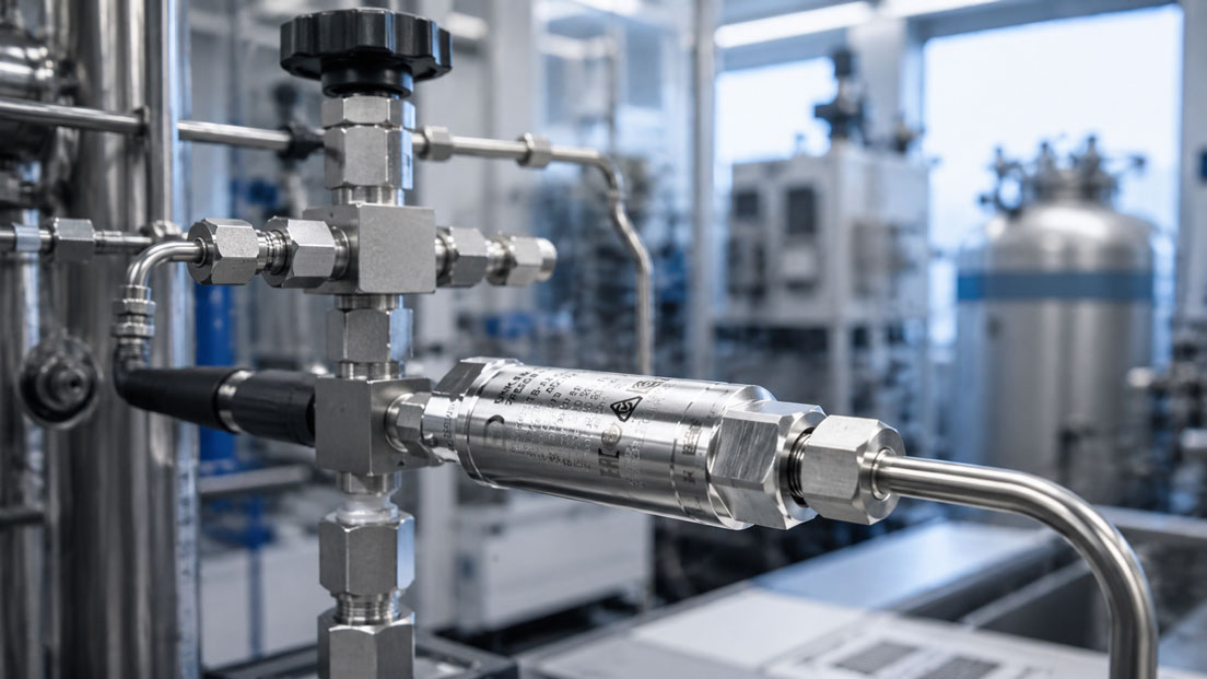
Hydrogen test benches place high demands on pressure measurement technology. In development, research, fuel cell testing, component testing and quality assurance, pressure values must not only be recorded safely, but also evaluated in a stable, precise and documentable way. This often involves not just a static pressure point, but pressure profiles, fast load changes, temperature changes and integration into data acquisition, PLC or test bench software.
A hydrogen pressure sensor in a test bench therefore has to do more than a simple standard pressure sensor. Decisive factors include hydrogen-compatible wetted materials, a suitable pressure range, appropriate accuracy, sufficient dynamics, a stable temperature range and an output signal that matches the existing measuring chain.
This article explains what must be considered for H2 pressure measurements in test benches, why fast pressure changes and long-term stability are particularly important, how 4–20 mA or voltage outputs can be tested effectively and why calibration, data loggers and the safety concept should be considered together from the start.
Table of contents
- Basics: Why hydrogen pressure measurement in test benches is particularly demanding
- Test bench applications: Where H2 pressure sensors are used
- Dynamics: Reliably capturing fast pressure changes
- Accuracy and stability: Why the measured value must be reliable
- Temperature range: Influence on sensor, measurement error and test sequence
- Materials and hydrogen compatibility
- Output signals: Combining mA, voltage and data acquisition correctly
- Testing 4–20 mA in the test bench: Why the UPS4E is useful
- Calibration and documentation in the H2 test bench
- Safety concept: Pressure measurement is only one part of the system
- Table: Selection criteria for hydrogen pressure sensors in the test bench
- Practical example: Pressure measurement in a fuel cell test bench
- Table: Typical errors in H2 pressure measurements in the test bench
- Which measuring instruments / products are suitable?
- Conclusion: Precise H2 pressure measurement requires the right measuring chain
- FAQ: Frequently asked questions about hydrogen pressure sensors in test benches
Basics: Why hydrogen pressure measurement in test benches is particularly demanding
Hydrogen is a special test medium. It has very small molecules, can place high demands on tightness and material selection, and is used under increased pressure in many applications. At the same time, many H2 applications are close to development, safety-relevant or quality-critical. Pressure measurement must therefore be designed reliably, reproducibly and appropriately for the test task.
A pressure sensor in a hydrogen test bench does not measure in isolation. It is part of a measuring chain consisting of process connection, sensor, electrical connection, data acquisition, test bench software, safety logic and documentation. If one of these elements does not fit, even a good sensor can provide incorrect or difficult-to-interpret measured values.
A particularly important question is whether the sensor is suitable for hydrogen. This is not only about the pressure range, but also about the wetted materials, seal, process connection, temperature conditions and, where applicable, approvals or safety requirements of the system.
Test benches also often involve changing operating states. Pressure build-up, pressure drop, purging processes, load changes, valve switching operations or fast control processes can place significant stress on the measuring point. Dynamics, accuracy and long-term stability must therefore be considered together.
Test bench applications: Where H2 pressure sensors are used
Hydrogen pressure sensors are used in very different test benches. These include fuel cell test benches, electrolyzer test benches, component test benches, leak tests, pressure control lines, storage and refueling components, valve tests, research systems and development test benches for H2 systems.
In a fuel cell test bench, for example, the pressure sensor can record the supply pressure, the differential pressure across a component or the pressure profile during a load change. In a component test bench, it can be checked how a valve, regulator, filter, compressor or storage component reacts to defined pressure states.
For development work, final values alone are not enough. It is often necessary to see how quickly pressure is built up, whether overshoots occur, whether a control loop operates stably or whether pressure pulsations arise. In such cases, the time profile of the pressure signal is more important than a single static measured value.
In quality assurance, by contrast, repeatability is often the main focus. The same test specimen type should deliver comparable measured values under identical conditions. For this, sensor, measuring range, calibration status, installation position and evaluation must be clearly defined.
Dynamics: Reliably capturing fast pressure changes
In many H2 test benches, pressures change quickly. Valves open and close, regulators respond to load changes, storage systems are filled or emptied, and test cycles run automatically. A pressure sensor must be able to capture these changes quickly enough if the pressure profile is to be evaluated.
Dynamics do not depend only on the sensor itself. Process connection, dead volume, damping, cable length, measured value filters, sampling rate and software evaluation also influence how quickly a pressure event becomes visible. A fast sensor is of little use if the signal is sampled too slowly in data acquisition or smoothed too heavily in the software.
For dynamic tests, it is therefore important to align the entire measuring chain with the test cycle. If short pressure peaks, overshoots or pulsations are to be evaluated, sensor frequency response, sampling rate and data recording must match this. If, on the other hand, a stable control value is to be documented, moderate damping may be useful to reduce noise and short-term disturbances.
Pressure peaks that occur only briefly but can stress components or safety functions are particularly critical. If they are not detected because the measuring chain is too slow, the test bench may appear stable even though relevant pressure events are occurring in the process.
Accuracy and stability: Why the measured value must be reliable
The required accuracy depends strongly on the test task. Simple monitoring often requires a different accuracy class than development, characteristic curve measurement, validation or comparison measurements between test specimens. In the test bench, the maximum pressure range should therefore not be selected as a blanket solution. Instead, a meaningful range with sufficient reserve and good usable resolution should be chosen.
A common mistake is using a sensor with a measuring range that is too large. The sensor is then well protected against overpressure, but in the actual working range it may provide poorer resolution and higher relative measurement uncertainty. Conversely, the sensor must not be selected so narrowly that pressure peaks or fault states overload it.
Long-term stability is also important. Test benches are often used for comparison measurements, series tests or long-term tests. If a sensor drifts over time, measured values may appear to show a process change even though the measuring point itself has actually changed.
For reliable results, accuracy, total error band, temperature behavior, repeatability, hysteresis and calibration interval should be evaluated together. Especially in development and research test benches, it is useful to document the measurement uncertainty of the entire measuring chain.
Temperature range: Influence on sensor, measurement error and test sequence
Temperature has several effects in H2 test benches. First, the pressure sensor itself must be suitable for the occurring ambient and media temperature range. Second, temperature influences measuring behavior, seals, materials, electronics and, where applicable, sensor compensation.
In fuel cell test benches, climate chambers or research systems, sensors can be exposed to changing temperatures. The test bench may start at room temperature and later be operated significantly warmer or colder. If the temperature behavior of the sensor is not taken into account, measured value changes can be incorrectly interpreted as process changes.
The installation position also plays a role. A sensor located directly near a warm component, compressor or temperature-controlled test area can experience different ambient conditions than the rest of the measuring chain. Cables, connectors and electronics must also match the temperature range.
For tests with documentation-required results, temperature should be recorded wherever possible. This makes it possible to determine later whether pressure changes actually originate from the process or whether temperature changes explain part of the measurement deviation.
Materials and hydrogen compatibility
Material selection is particularly important in hydrogen applications. Wetted parts must be suitable for the planned pressure, temperature and H2 conditions. Depending on the application, hydrogen embrittlement, permeation, tightness, surface quality and mechanical load can play a role.
A sensor for general gases is not automatically suitable for hydrogen test benches. Even if pressure range and output signal match, materials, seals or process connection may be unsuitable for H2 applications. Hydrogen compatibility should therefore always be checked based on the specific sensor version.
In test benches, stainless steel housings and suitable wetted materials are often used. However, the sensor is not the only decisive factor; the entire measuring point is important. Adapters, seals, valves, fittings and pipes must also match the medium and the safety concept.
At high pressures, under cyclic load or during dynamic test cycles, it should also be evaluated how mechanical stress affects the service life of the measuring point. A stable measured value starts with an installation that is suitable both mechanically and in terms of materials.
Output signals: Combining mA, voltage and data acquisition correctly
Depending on the version, hydrogen pressure sensors can provide different output signals. In test benches, 4–20 mA, 0–10 V, other voltage outputs, mV signals or digital interfaces are possible. The selection should match the measuring task and the existing data acquisition system.
A voltage output can be interesting in test benches when short cable runs, fast acquisition and direct connection to a data acquisition system are the main priorities. Interference, ground references and cable routing must be considered carefully.
A 4–20 mA signal is particularly robust for industrial environments and longer cable runs. It is well suited for PLCs, process control systems and test benches where a standardized signal must be transmitted reliably. The current range also makes it easier to evaluate wire breaks or fault signals, provided that the measuring chain is designed accordingly.
For evaluation, it is decisive that signal type, measuring range and scaling match. If a sensor measures 0…400 bar but the data acquisition is scaled to 0…250 bar, incorrect values occur even though the sensor is working correctly. Signal testing should therefore always be part of commissioning.
Testing 4–20 mA in the test bench: Why the UPS4E is useful
If a hydrogen pressure sensor with a 4–20 mA output is used, the current loop should be tested specifically. Especially in a test bench, it is important that not only the sensor itself works, but also that the signal is transmitted correctly to the PLC, data logger, display or test bench software.
The UPS4E current loop calibrator / loop calibrator is suitable for this task. It can measure and simulate mA signals and helps separate sensor, wiring, input card and scaling from one another.
A useful test procedure is to first measure the real mA signal of the pressure sensor at defined pressure points. Then an mA signal can be simulated directly at the PLC or data acquisition input. This makes it possible to determine whether a deviation is caused by the sensor, the cable, the analog input or the software scaling.
This separation is particularly helpful for recurring test bench tests. If a pressure value appears implausible, the sensor does not immediately have to be removed. In many cases, mA measurement and mA simulation already show whether the electrical measuring chain is working correctly.
Calibration and documentation in the H2 test bench
Test benches often provide data used for development, approval, quality assurance or research reports. The calibration status of the pressure sensors used must therefore be known. A sensor without traceable calibration can provide a value, but the significance of the test report is limited.
Calibration should match the measuring range and the test task. If a sensor is evaluated particularly accurately in a narrow working range, calibration over relevant test points may be more useful than only a general assessment across the full nominal range.
Documentation of the measuring chain is also important. This includes sensor designation, serial number, measuring range, output signal, scaling, calibration status, installation position, data acquisition rate and software version of the evaluation. Only then do measurement results remain traceable later.
For H2 test benches, it should also be documented under which pressure, temperature and operating conditions the measurement was carried out. This improves comparability between test runs and helps to classify deviations correctly.
Safety concept: Pressure measurement is only one part of the system
Hydrogen is flammable and requires a suitable safety concept. Pressure measurement can play an important role, but it does not replace a complete safety-related assessment of the test bench. Pressure sensors provide measured values for monitoring, control and documentation. Safety functions, however, must be planned and evaluated according to the system requirements.
Depending on the test bench, overpressure protection, leak detection, ventilation, gas warning, emergency shutdown, explosion protection, safe venting and suitable materials may be required. Which measures are necessary depends on pressure, gas quantity, room, application, operating mode and applicable regulations.
The selection of the pressure sensor should be embedded in this safety concept. This includes suitable pressure ranges, overpressure resistance, electrical connections, protection class, possible Ex requirements and defined behavior in the event of signal faults.
Work on hydrogen systems and test benches may only be carried out by qualified personnel. Before commissioning, modification or sensor replacement, the system, medium, pressure state and safety requirements must be clearly evaluated.
Table: Selection criteria for hydrogen pressure sensors in the test bench
| Criterion | Why important? | Practical effect |
|---|---|---|
| Hydrogen compatibility | Wetted parts must be suitable for H2 | Specifically check materials, seals and process connection |
| Pressure range | Operating pressure and pressure peaks must be recorded safely | Select measuring range with reserve, but not unnecessarily large |
| Dynamics / frequency response | Fast pressure changes should remain visible | Align sensor, sampling rate and software filter with the test cycle |
| Accuracy | Measured values must match the test task | Consider total error band, temperature behavior and calibration |
| Temperature range | Environment and medium influence sensor and measurement error | Document temperature and choose suitable sensor version |
| Output signal | Signal must match the data acquisition system | Select 4–20 mA, voltage or digital signal appropriately |
Practical example: Pressure measurement in a fuel cell test bench
In a fuel cell test bench, the hydrogen pressure is to be recorded during various load profiles. The test bench approaches defined pressure points, simulates load changes and documents the pressure profile together with temperature, flow and electrical power.
An H2-suitable pressure sensor is selected so that pressure range, wetted materials, temperature range and output signal match the system. Since fast pressure changes during load changes should remain visible, frequency response, sampling rate and software filters are also checked.
During commissioning, the sensor is first compared with defined pressure points. The output signal is then checked in the data acquisition system. With a 4–20 mA sensor, the current loop is additionally checked so that it is clear whether sensor value, mA signal and software display match.
During later operation, the recording shows that short pressure overshoots occur during certain load changes. These would hardly have been visible with a heavily smoothed or too slowly sampled measuring chain. With the right sensor and data acquisition selection, the test bench can evaluate not only final values, but also the dynamic behavior of the system.
Table: Typical errors in H2 pressure measurements in the test bench
| Error | Possible consequence | Better approach |
|---|---|---|
| Standard pressure sensor selected without H2 check | Material or seal problem during operation | Check hydrogen compatibility of the specific version |
| Measuring range selected too large | Poorer usable resolution in the working range | Design operating pressure, peaks and safety reserve together |
| Sampling rate too low | Fast pressure events are not detected | Select sensor frequency response and data acquisition appropriately |
| Software filter set too strongly | Pressure peaks or pulsations are smoothed | Adjust filtering deliberately to the test objective |
| 4–20 mA scaling incorrect | PLC or data logger displays incorrect pressure values | Check mA signal with UPS4E and verify scaling |
| Calibration status unclear | Test results are difficult to trace | Define calibration and measuring chain documentation |
Which measuring instruments / products are suitable?
For hydrogen test benches, fuel cell applications, component testing and research, the UNIK 5000H analog pressure sensor for hydrogen applications is a suitable solution when an H2-optimized analog pressure sensor with high accuracy, stability and suitable output signals is required.
For a broader selection of pressure measurement solutions, the category pressure sensors / differential pressure sensors is also relevant. It includes different sensor and transmitter solutions for gauge pressure, absolute pressure, differential pressure, test benches, process applications and automation.
If H2 applications are the main focus, the category H² pressure sensors is also useful. There, pressure sensors for hydrogen applications are grouped together, where material selection, pressure range and signal type must specifically match the application.
For 4–20 mA outputs, the UPS4E current loop calibrator / loop calibrator should be planned as a test instrument. It helps to measure or simulate mA signals and check the current loop up to the PLC, display or data acquisition system.
For the complete test bench, further measured variables are often important, for example temperature, flow, electrical power, valve status or gas warning technology. Only the combined recording of these values enables a reliable assessment of the H2 system.
Conclusion: Precise H2 pressure measurement requires the right measuring chain
A hydrogen pressure sensor in the test bench must match the entire application. The decisive factors are not only pressure range and connection thread, but also hydrogen compatibility, dynamics, accuracy, temperature range, output signal, calibration and integration into data acquisition.
Especially in fuel cell test benches, component tests and research systems, pressure profiles are often more important than individual final values. Fast pressure changes, overshoots or pulsations only become visible when sensor, measuring chain and software evaluation are designed appropriately.
With an H2-suitable sensor such as the UNIK 5000H, clean measuring chain documentation, suitable calibration and targeted testing of 4–20 mA signals with the UPS4E, a pressure measuring point is created that not only provides values, but reliably supports the test bench.
FAQ: Frequently asked questions about hydrogen pressure sensors in test benches
Why do you need a special pressure sensor for hydrogen?
Hydrogen places special demands on materials, tightness and process connection. A standard pressure sensor is not automatically suitable for H2. The decisive factor is that the specific sensor version is designed for hydrogen applications.
Which pressure ranges are typical in H2 test benches?
This depends strongly on the application. Fuel cell test benches, component tests, storage applications or pressure control lines can require very different ranges. It is important to evaluate operating pressure, pressure peaks and safety reserve together.
Why should the measuring range not be selected unnecessarily large?
A very large measuring range can lead to poorer usable resolution and higher relative measurement uncertainty in the actual working range. The sensor should have sufficient reserve, but still match the actual test task.
What does dynamics mean for a pressure sensor?
Dynamics describe how well the sensor can capture fast pressure changes. In test benches, this is important when load changes, valve switching operations, pressure peaks or pulsations need to be evaluated.
Why is an accurate sensor alone not enough?
The entire measuring chain influences the result. Process connection, line, sampling rate, software filter, signal type, scaling and calibration can change the displayed pressure value or hide fast events.
When is a 4–20 mA output useful?
4–20 mA is useful when a robust industrial signal is to be transmitted over longer cable runs to a PLC, data logger or control system. The current loop can also be tested and monitored well.
How do you test a 4–20 mA signal in the H2 test bench?
The mA signal can be measured or simulated with a loop calibrator such as the UPS4E. This makes it possible to check whether sensor, wiring, input card and scaling work together correctly.
When is a voltage output better suited?
A voltage output can be useful when short cable runs and fast data acquisition are the main priorities. Interference, grounding and EMC must be considered carefully.
Why is temperature important in the test bench?
Temperature influences sensor behavior, electronics, seals and measurement deviation. When pressure values are documented or compared, temperature should also be recorded or at least considered.
What must be considered with fast pressure peaks?
Sensor frequency response, sampling rate and software filters must be fast enough. Otherwise, pressure peaks can be smoothed or missed completely, even though they are relevant for component load and safety.
How often should an H2 pressure sensor in the test bench be calibrated?
This depends on usage, accuracy requirements, internal test equipment monitoring and load. In quality- or development-relevant test benches, the calibration status should be checked and documented regularly.
What should be included in measuring chain documentation?
Useful information includes sensor designation, serial number, measuring range, output signal, scaling, calibration status, installation position, data acquisition rate, software version and relevant test conditions such as pressure and temperature.
Can a pressure sensor replace safety functions?
No. A pressure sensor can provide measured values for monitoring and control, but it does not replace a complete safety concept. Overpressure protection, leak detection, gas warning and shutdowns must be evaluated for the specific system.
What role does the installation position play?
The installation position influences pressure dynamics, temperature load, dead volume and maintainability. An unfavorable installation can mean that the sensor does not record the actually relevant pressure profile.
Which additional measured variables are useful in the H2 test bench?
Temperature, flow, valve position, electrical power, gas warning signals and switching states are often important. Only the combination of several measured variables enables safe interpretation of the test sequence.