


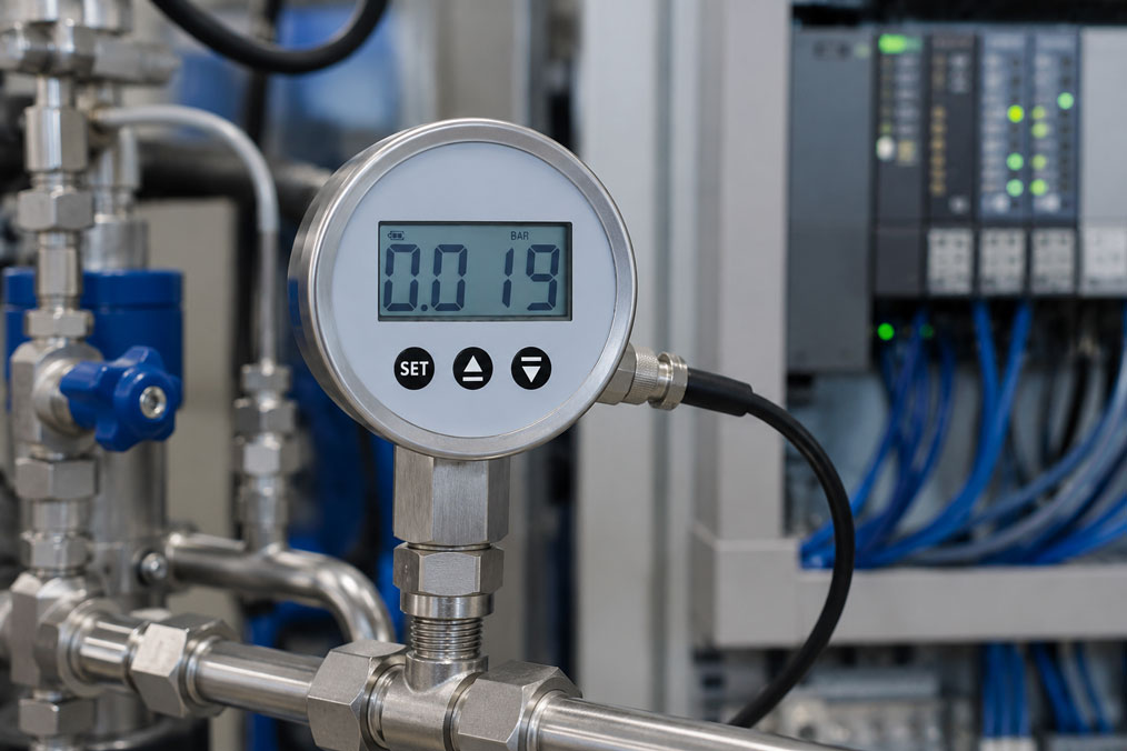
A digital pressure gauge is often used when the pressure should be easy to read directly on site. In many applications, however, the local display alone is not sufficient. The measured value should also be transmitted to a PLC, data logger, test bench, control system or process monitoring system. This is exactly where digital pressure gauges with an output signal come into play.
They combine two functions in one device: direct pressure indication at the measuring point and an electrical output signal for further processing. This makes them particularly suitable for test benches, service tasks, mechanical engineering, hydraulics, pneumatics, water technology, wastewater technology and systems where the operator wants to see the pressure locally while measurement data is recorded or monitored at the same time.
In practice, the question then often arises: should the digital pressure gauge have a 4–20 mA output, or is RS485 the better choice? The answer depends on whether a single robust analog signal is required or whether digital communication, multiple measuring points and structured data transmission are more important.
Table of contents
- Basics: What is a digital pressure gauge with output signal?
- Local display plus signal transmission: why this combination makes sense
- 4–20 mA: the robust standard for PLC and process monitoring
- RS485: digital data transmission for bus and multi-point applications
- 4–20 mA or RS485 in direct comparison
- Digital pressure gauge or pressure transmitter: what is the difference?
- Typical applications in test benches, hydraulics and plant engineering
- Connection, power supply, scaling and data logger integration
- Practical example: pressure display and measurement data acquisition in a test bench
- Which measuring instruments / products are suitable?
- Conclusion: the right output signal depends on the measuring task
- FAQ: Frequently asked questions about digital pressure gauges with output signal
Basics: What is a digital pressure gauge with output signal?
A digital pressure gauge is a pressure measuring instrument with an electronic measuring cell and digital display. It shows the pressure value directly on the device, usually in units such as bar, mbar, kPa, PSI or MPa. Unlike a classic mechanical pressure gauge with a pointer, the pressure is recorded electronically and shown on a display.
A digital pressure gauge with output signal goes one step further. It also provides the measured pressure as an electrical signal. This signal can be processed by a PLC, data logger, display, controller or test bench software. This turns a purely local display device into a measuring instrument that can also be integrated into automated systems.
Typical output signals are 4–20 mA or digital interfaces such as RS485. A 4–20 mA signal is particularly suitable for classic process automation and analog inputs. RS485 is interesting when several devices are to communicate via a bus line or when measured values are to be transmitted digitally.
It is important to distinguish this from a pressure transmitter. In many cases, a pressure transmitter is primarily designed for signal transmission to the control system and does not always have an easily readable local display. A digital pressure gauge with output signal, on the other hand, is particularly useful when the on-site display is just as important as the electrical signal.
| Device type | Main function | Typical advantage |
|---|---|---|
| Mechanical pressure gauge | Local pressure indication via pointer | Simple, robust, no electrical power supply required |
| Digital pressure gauge | Local digital pressure indication | Better readability, higher resolution, additional functions such as min/max or zero point correction |
| Digital pressure gauge with output signal | Local display and electrical signal transmission | Pressure visible on site and simultaneously transmittable to PLC, logger or test bench |
| Pressure transmitter | Continuous pressure transmission to control system or process control system | Compact process measurement for permanent automation |
Local display plus signal transmission: why this combination makes sense
In many systems, the local display is a major practical advantage. A service technician, maintenance engineer or plant operator can check the pressure directly at the measuring point without first having to open a PLC screen, laptop or control system. At the same time, the measured value can be automatically documented, monitored or further processed.
This combination is particularly useful when measuring points are checked regularly on site. A classic pressure transmitter can provide a very good signal, but without a display at the measuring point it is less convenient. A pure digital pressure gauge shows the pressure, but without an output signal it does not provide continuous data to the control system. A digital pressure gauge with output signal closes this gap.
Typical applications include test benches, mobile or stationary hydraulic systems, compressed air systems, pump tests, filter monitoring, water and wastewater technology or machines where the operator needs a quick plausibility check directly on the device. Especially during commissioning and service, it helps if the local value and the PLC value can be compared with each other.
Another advantage is retrofit capability. If a pressure gauge is already planned at an existing measuring point, but an additional signal for documentation or monitoring is required in the future, a digital pressure gauge with signal output can be a pragmatic solution. The prerequisite is that process connection, measuring range, power supply, protection rating and output signal match the application.
4–20 mA: the robust standard for PLC and process monitoring
The 4–20 mA signal is one of the most important standards in industrial process measurement technology. The measured pressure is scaled to a current range from 4 to 20 mA. 4 mA typically corresponds to the lower end of the measuring range, 20 mA to the upper end of the measuring range. A pressure range from 0 to 100 bar, for example, would therefore be scaled so that 4 mA stands for 0 bar and 20 mA for 100 bar.
The advantage of this signal lies in its robustness. Current signals are less sensitive to cable resistance than voltage signals. This makes 4–20 mA well suited for industrial environments, longer cables and connection to PLC analog inputs, data loggers or process displays. In addition, a signal below 4 mA can be interpreted in many systems as an indication of cable break or fault condition.
A digital pressure gauge with 4–20 mA output is particularly useful when exactly one pressure value is to be continuously transmitted to a control system. The PLC can monitor the pressure, process limit values, record trends or use the value for control and safety functions. On site, the pressure remains directly readable on the pressure gauge.
Correct scaling is important. The analog signal only makes sense if measuring range, output signal and PLC input match each other. If a 0–250 bar pressure gauge is incorrectly scaled in the PLC as 0–100 bar, the displayed values will not be correct. Errors often do not arise in the measuring instrument itself, but from incorrect parameterization, wiring or channel assignment.
RS485: digital data transmission for bus and multi-point applications
RS485 is a serial interface used in many industrial applications for robust digital communication. Unlike 4–20 mA, it does not transmit just an analog current value, but a digital measured value. Depending on the protocol and system structure, several devices can communicate via a common bus line.
A digital pressure gauge with RS485 output is particularly interesting when several pressure measuring points are to be recorded digitally. Instead of providing a separate analog input for each measuring point, several devices can be integrated into a bus system. In suitable applications, this reduces wiring effort and simplifies structured data acquisition.
RS485 can also offer advantages when measured values are to be transmitted directly to a data logger, industrial PC, test bench software or digital monitoring system. The pressure value is then available digitally and does not have to be recalculated from an analog signal. Depending on the system, additional information such as device address, status or several parameters can be transmitted.
However, RS485 requires clean planning. Bus address, protocol, terminating resistors, cable length, shielding, topology and evaluation hardware must match. While 4–20 mA is very easy to understand for many electricians and PLC applications, RS485 requires more attention regarding communication and parameterization.
4–20 mA or RS485 in direct comparison
The decision between 4–20 mA and RS485 should not be based only on personal preference. The decisive factor is how the measured value is further processed. If a single pressure value is to be transmitted to a classic PLC analog input, 4–20 mA is usually the obvious solution. If several measuring points are to be read digitally or integrated into test bench software, RS485 can be more useful.
The existing infrastructure also plays an important role. In many industrial plants, analog inputs for 4–20 mA are already available. In test benches, laboratories or data acquisition systems, on the other hand, a digital interface can be advantageous because measured values are processed directly in software.
| Criterion | 4–20 mA | RS485 |
|---|---|---|
| Signal type | Analog current signal | Digital serial communication |
| Typical use | PLC analog input, process display, classic data logger | Bus connection, test bench software, digital data acquisition |
| Wiring | One signal per measuring point | Several participants possible via one bus line, depending on the system |
| Commissioning | Usually simple if measuring range and scaling are known | Requires address, protocol, interface parameters and bus structure |
| Troubleshooting | Current value can be measured or simulated directly | Communication must be checked with suitable software or interface |
| Particularly useful for | Individual measuring points, robust standard signal, PLC connection | Several measuring points, digital documentation, test bench or PC connection |
Digital pressure gauge or pressure transmitter: what is the difference?
At first glance, a digital pressure gauge with output signal and a pressure transmitter can perform similar tasks. Both record pressure electronically and can provide a signal. The difference lies mainly in the operating and application concept.
A pressure transmitter is usually designed for permanent integration into a system. It continuously supplies a signal to the control system and is often used where no local display is required. The design is compact, and the focus is on electrical integration. Many transmitters are designed for harsh process conditions, high protection ratings, various process connections or special media.
A digital pressure gauge with output signal, on the other hand, is particularly interesting when the pressure value should be visible directly at the measuring point. It is well suited for test benches, service areas, machines with operator access or systems where the local comparison between display and control system is important. The digital display supports commissioning and makes quick on-site checks easier.
For pure automation tasks, a pressure transmitter can be the more economical and robust solution. For applications where display, output signal and operation on the device are equally important, the digital pressure gauge with signal output is often more practical.
| Requirement | Digital pressure gauge with output signal | Pressure transmitter |
|---|---|---|
| Local pressure display | Available directly on the device | Not always available or only optional |
| Permanent PLC connection | Possible, especially with 4–20 mA or RS485 | Typical main application |
| Test bench and service | Very well suited, as display and signal are combined | Suitable if no local display is required |
| Compact machine integration | Must be checked depending on available installation space | Often available in very compact designs |
| On-site plausibility check | Very simple via display | Usually only via PLC, handheld device or additional display |
Typical applications in test benches, hydraulics and plant engineering
Digital pressure gauges with output signal are particularly often used where measured values should be locally visible and documentable at the same time. In test benches, this is a typical case. The operator sees the pressure directly on the measuring instrument, while the test bench computer records the value. This allows pressure curves to be evaluated later and compared with other measured variables.
In hydraulics and pneumatics, a digital pressure gauge with signal output can be used to monitor system pressure, test pressures, filter conditions or pressure drops. The local display helps with troubleshooting, while the output signal supports limit values, trend recording or process releases.
In water and wastewater technology, such devices are useful when pumps, pipes, filters or tanks need to be monitored. The pressure value can be checked on site without having to connect a separate handheld measuring instrument. At the same time, pressure changes can be transmitted to a control system or data logger.
In mechanical and plant engineering, digital pressure gauges with output signal are particularly interesting for modular systems, service points and commissioning areas. They allow simple visual inspection and still provide an interface to automation. This can offer practical added value for both operators and service or maintenance personnel.
Connection, power supply, scaling and data logger integration
When selecting a digital pressure gauge with output signal, process connection, electrical connection and signal processing must be considered together. Mechanically, measuring range, pressure connection, medium, seal, material and installation position must fit. Electrically, supply voltage, output signal, wiring and input type of the target system are decisive.
For 4–20 mA devices, the current loop must be correctly set up. This includes a suitable power supply, correct polarity, sufficient load resistance and a correctly parameterized analog input. The PLC or data logger must know which pressure range is assigned to the current signal. Only then does the measured current value become a correct pressure value.
For RS485 devices, other points are central. Here, bus cable, address, communication parameters, protocol and evaluation software must match. In many applications, it is useful to first test communication with a single device and only then integrate several participants.
The UPS4E loop calibrator is a suitable tool for testing 4–20 mA signals. It allows the loop current to be measured, a defined mA value to be simulated and the scaling on the PLC, data logger or control system to be checked. This is particularly helpful during commissioning when it is not clear whether a fault lies with the digital pressure gauge, the wiring or the parameterization.
| Test point | Why important? | Typical error if ignored |
|---|---|---|
| Measuring range | Determines the scaling of display and output signal | PLC displays incorrect pressure values or uses only part of the range |
| Supply voltage | Required for electronics, display and output | Unstable display, no output signal or communication error |
| 4–20 mA scaling | Assigns 4 mA and 20 mA to the correct pressure range | Deviation between pressure gauge display and PLC value |
| RS485 address | Enables clear communication with the device | No communication or the wrong participant is read out |
| Media compatibility | Protects measuring cell and process connection | Corrosion, clogging, diaphragm damage or measurement deviation |
Practical example: pressure display and measurement data acquisition in a test bench
A machine builder operates a hydraulic test bench. During the test, the operator should see the pressure directly on the system. At the same time, the pressure curve should be stored in the test bench computer so that it can later be documented whether the test specimens complied with the required pressure curve.
A purely mechanical pressure gauge is not sufficient for this because no electrical signal is available for data acquisition. A simple pressure transmitter would provide a signal, but would not offer the operator a direct local display. Therefore, a digital pressure gauge with output signal is used.
If the test bench has only one or a few pressure measuring points and the existing control system uses classic analog inputs, a 4–20 mA output is an obvious choice. The pressure is shown on the device and simultaneously transmitted as a current signal to the data logger or PLC. During commissioning, a loop calibrator is used to check whether 4 mA and 20 mA correctly correspond to the set pressure range.
If several pressure measuring points are to be recorded digitally in the test bench and the test bench software supports bus communication, RS485 can be the better solution. Several measuring instruments can then be read out in a structured way, and the measured values are available directly in digital form for documentation. The decisive factor is that interface, protocol and software match properly.
Which measuring instruments / products are suitable?
For applications where a local pressure display and an output signal are required, the IDM-60A/R digital pressure gauge with output signal is suitable. The IDM-60A version is interesting for applications with analog 4–20 mA output. The IDM-60R version is suitable for applications where an RS485 bus system is to be used.
The device is particularly suitable when pressure should be locally readable and, at the same time, a signal is required for control system, data logger, test bench or process monitoring. Typical areas of application are hydraulics, pneumatics, water and wastewater technology as well as plant and mechanical engineering. For higher requirements, a more accurate device variant may be useful depending on version and option.
The digital pressure gauges / test gauges category is useful when different digital pressure gauges are to be compared. In addition to devices with signal output, it also includes battery-operated precision digital pressure gauges, precision digital pressure gauges and contact pressure gauges for different tasks.
If no local display is required and the signal is to be permanently integrated into a control system, a classic pressure transmitter may alternatively be the more suitable solution. If, on the other hand, display, usability and output signal are equally important, a digital pressure gauge with signal output is often the more practical choice.
For 4–20 mA applications, a suitable test instrument for commissioning and troubleshooting should also be planned. The UPS4E loop calibrator helps to measure and simulate mA signals, check loop supply and verify scaling between digital pressure gauge, data logger, PLC or control system.
| Product / area | Typical use | Particularly relevant for |
|---|---|---|
| IDM-60A/R digital pressure gauge with output signal | Local digital pressure display with 4–20 mA or RS485 output | Test benches, hydraulics, pneumatics, mechanical engineering, water and wastewater technology |
| IDM-60A | Digital pressure gauge with analog 4–20 mA output | PLC connection, process monitoring, data logger with analog input |
| IDM-60R | Digital pressure gauge with RS485 output | Digital data acquisition, bus connection, several measuring points and test bench software |
| Digital pressure gauges / test gauges | Selection of various digital pressure display devices | Service, testing, calibration, process control and local pressure indication |
| UPS4E loop calibrator | Testing and simulation of 4–20 mA signals | Commissioning, PLC scaling, troubleshooting and signal testing |
Conclusion: the right output signal depends on the measuring task
A digital pressure gauge with output signal is useful when the pressure should be visible directly on site and, at the same time, an electrical signal is required for control system, data logger, test bench or process monitoring. It combines the advantages of a local digital display with the possibility of further processing and documenting measured values.
4–20 mA is usually the right choice when a single pressure value is to be transmitted robustly to a PLC analog input, process display or classic data logger. RS485 is particularly interesting when several measuring points are to be read digitally or when test bench or PC-based data acquisition is planned.
The most important recommendation is: before selection, it should be clear how the measured value will be used. Should the operator check the pressure locally? Should the PLC monitor a limit value? Should a test bench document the pressure curve? Or should several devices be read out digitally? Only then do output signal, measuring range, accuracy, process connection, power supply and integration into the system determine the suitable device version.
FAQ: Frequently asked questions about digital pressure gauges with output signal
What is a digital pressure gauge with output signal?
A digital pressure gauge with output signal displays the pressure digitally directly on the device and also outputs the measured value as an electrical signal. This signal can be transmitted, for example, to a PLC, data logger, display or test bench system.
When is a digital pressure gauge with 4–20 mA useful?
A digital pressure gauge with 4–20 mA is useful when a pressure value needs to be transmitted robustly and continuously to a PLC, control system or data logger. It is particularly suitable for individual measuring points, classic process automation and applications where an analog signal can be processed easily.
When is a digital pressure gauge with RS485 useful?
RS485 is useful when measured values are to be transmitted digitally or several devices are to be read out via a bus structure. This is particularly interesting for test benches, PC-based data acquisition, multi-point measurements and applications where digital communication better matches the existing infrastructure.
What is the difference between 4–20 mA and RS485?
4–20 mA is an analog current signal. The pressure value is transmitted as a current between 4 and 20 mA. RS485 is a digital interface through which measured values are transmitted serially. 4–20 mA is usually easier for PLC analog inputs. RS485 is advantageous for digital data acquisition and several measuring points.
Is a digital pressure gauge with output signal a replacement for a pressure transmitter?
In some applications yes, but not always. If local display and output signal are needed at the same time, a digital pressure gauge with signal output can be very useful. If only a permanent signal for the control system is required and no local display is needed, a classic pressure transmitter is often the more suitable solution.
Why does the PLC show a different value than the digital pressure gauge?
The cause is often scaling or wiring. The PLC analog input must match the measuring range of the digital pressure gauge. If 4 mA and 20 mA are assigned incorrectly or the input has been parameterized for a different range, the PLC will display a deviating pressure value.
How do you test a 4–20 mA output signal?
The output signal can be checked with a loop calibrator or a suitable measuring instrument. This involves checking whether the loop current matches the displayed pressure. In addition, a defined mA value can be simulated in order to check the scaling of the PLC, data logger or control system independently of the pressure measuring instrument.
Can a digital pressure gauge with output signal be used in a test bench?
Yes, test benches are a typical application. The operator can read the pressure locally on the display while the measured value is simultaneously transmitted to a test bench computer or data logger. This allows pressure curves to be documented and evaluated later.
What advantages does RS485 offer with several measuring points?
With several measuring points, RS485 can reduce wiring effort because several devices can be read out via one bus line, depending on the system. In addition, the measured values are available digitally. This is useful when a test bench computer, industrial PC or digital monitoring system is used.
What disadvantages does RS485 have compared with 4–20 mA?
RS485 requires more attention regarding address, protocol, bus structure, terminating resistors, communication parameters and software. For simple PLC applications, 4–20 mA is often faster to commission because only the current loop and scaling need to be set up correctly.
What should be considered when selecting the measuring range?
The measuring range should match the process. It must not be selected too small in order to avoid overloads. However, it should also not be unnecessarily large, because otherwise resolution and usable signal range may fit the actual application less well. The typical operating pressure should lie sensibly within the measuring range.
Can a digital pressure gauge with signal output be used for hydraulics?
Yes, hydraulics is a typical application, provided that measuring range, pressure peaks, process connection, media compatibility and electrical power supply are suitable. Especially in test benches, service points and machines, the combination of local display and output signal can be very practical.
What should be considered regarding the power supply?
A digital pressure gauge with output signal requires a suitable electrical power supply. Voltage, wiring, polarity and load resistance must match the device and the target system. An unstable or incorrect power supply can lead to failures, incorrect signals or communication problems.
What role does accuracy play?
The accuracy should match the measuring task. Standard accuracy is often sufficient for simple monitoring. Higher accuracy may be required for test benches, quality documentation or calibration comparisons. The entire measuring chain should always be considered, not just the pressure gauge itself.
Can a digital pressure gauge with output signal be permanently used in the process?
Yes, if the device is suitable for the process conditions, medium, temperature, protection rating, pressure range and installation situation. In harsh environments, with vibrations, pressure peaks or aggressive media, the design should be checked carefully.
What should be clarified before selecting a digital pressure gauge with output signal?
Important points include pressure range, medium, process connection, accuracy, local display, output signal, target system, power supply, installation position, protection rating, data logger or PLC connection and the question of whether 4–20 mA or RS485 better fits the existing system.