


When a thermocouple displays incorrect temperatures, the sensor itself is often suspected first. In practice, however, the cause is often not the sensing element, but the entire measuring chain: wrong thermocouple type, unsuitable compensating cable, poor thermal coupling, incorrect installation position, EMC interference, cable break, faulty cold junction compensation or an incorrectly parameterized display or PLC.
Thermocouples are robust and versatile temperature sensors. They are suitable for high temperatures, fast temperature changes and many industrial applications. At the same time, they operate with very small voltages in the millivolt range. This makes them sensitive to incorrect cables, poor contacts, interference and unsuitable connection points.
This article explains in practical terms why a thermocouple can display incorrect values, how to identify the most common causes and how thermocouples can be systematically checked using comparison measurement, visual inspection, cable testing and a temperature calibrator.
Table of contents
- Basics: How a thermocouple measures
- Typical fault patterns: What does the system show?
- Wrong thermocouple type: Type K, J, T, N and others
- Compensating cable, extension cable and connection errors
- Installation errors: contact, immersion depth and heat dissipation
- Cold junction compensation and terminal temperature
- EMC, grounding problems and grounded measuring junctions
- Checking a thermocouple: comparison measurement and temperature calibrator
- Practical example: oven displays 40 °C too low
- Which measuring instruments / products are suitable?
- Conclusion: always check the entire measuring chain when thermocouple values are incorrect
- FAQ: Frequently asked questions about incorrect thermocouple readings
Basics: How a thermocouple measures
A thermocouple consists of two different metallic conductors that are joined together at the measuring point. When there is a temperature difference between the measuring point and the connection point, a very small thermoelectric voltage is generated. This voltage is typically in the millivolt range and is evaluated by a display, temperature controller, data logger, transmitter or PLC input card.
A thermocouple therefore does not simply measure an absolute temperature like a digital thermometer. It generates a voltage that depends on the temperature difference between the measuring point and the reference junction. In order to turn this into a correct temperature value, the evaluation device must know the thermocouple type and compensate for the temperature at the connection point. This so-called cold junction compensation is an important part of the measurement.
In practice, this means that a thermocouple only works correctly if sensor, cable, connector, terminals, evaluation unit and installation situation match. Even an incorrectly selected compensating cable or an incorrectly configured sensor type can cause significant deviations, even though the sensor itself is not defective.
Thermocouples are often used where high temperatures, fast response times or robust sensor designs are required. Typical applications include ovens, exhaust ducts, machines, plastics processing, heat treatment, laboratory tests, test benches, surface measurements and temporary service measurements.
Typical fault patterns: What does the system show?
Before a thermocouple is replaced, the fault pattern should be examined carefully. A permanently too high or too low value often has different causes than a jumping measured value or a display that only becomes unstable when the machine is running. The type of deviation provides important clues to the cause.
A constant offset often indicates a wrong thermocouple type, faulty cold junction compensation or incorrect parameterization. A strongly fluctuating value can be caused by a loose contact, cable break, EMC interference or poor terminal connections. A sluggish measured value often points to poor thermal coupling, overly large thermowells, incorrect installation position or insufficient immersion depth.
| Fault pattern | Probable cause | Practical assessment |
|---|---|---|
| Measured value constantly too high or too low | Wrong thermocouple type, incorrect parameterization, wrong compensating cable | First check type, cable, terminals and settings of the evaluation unit. |
| Measured value jumps or briefly drops out | Loose contact, cable break, loose terminal, EMC coupling | Move the cable, check terminals, consider sources of interference and shielding. |
| Measured value responds very slowly | Poor thermal coupling, overly massive thermowell, incorrect sensor position | Check installation situation and thermal contact, not only the sensor. |
| Display remains at ambient temperature | Sensor not in the process, interruption, wrong input or incorrect wiring | Systematically trace the signal path from the sensor to the display. |
| Fault occurs only when motors or heaters are running | EMC, grounding problem, potential differences, unsuitable cable routing | Check cable routing, grounding, grounded/ungrounded measuring junction and shielding concept. |
Wrong thermocouple type: Type K, J, T, N and others
One of the most common causes of incorrect temperature values is an incorrectly set or incorrectly connected thermocouple type. Thermocouples are not interchangeable at will. Type K, Type J, Type T, Type N, Type E, Type R, Type S and Type B have different material pairings and different characteristic curves. The evaluation device must be set exactly to the type used.
For example, if a Type J thermocouple is evaluated at an input that is parameterized for Type K, the displayed temperature value can deviate significantly. The error is not always immediately recognizable as “impossible”. Especially at medium temperatures, the value may appear plausible but still be wrong. This is particularly critical when processes are released, documented or controlled.
Errors also occur with replacement sensors. In maintenance, an available sensor is sometimes installed that fits mechanically but does not electrically correspond to the original thermocouple type. Connector colors, markings or old documentation can also be misinterpreted. For this reason, the sensor type should always be checked on the sensor, cable, connector and in the parameterization.
| Thermocouple type | Typical application | What to pay particular attention to? |
|---|---|---|
| Type K | Very common in industry, furnace construction, mechanical engineering and service | Sensor, connector and cable must consistently correspond to Type K. |
| Type J | Industrial applications, older systems, more limited high-temperature ranges | Do not accidentally evaluate as Type K; observe material pairing. |
| Type T | Lower temperatures, laboratory, refrigeration applications | Pay particular attention to suitable compensating cable and correct parameterization. |
| Type N | Higher temperatures and applications with better long-term stability | The evaluation unit must explicitly support Type N. |
| Type R / S / B | High temperature, laboratory, oven and calibration applications | Usually requires a more demanding measuring chain, suitable cables and calibration. |
Compensating cable, extension cable and connection errors
With thermocouples, the cable is part of the measuring chain. This is a key difference compared with many other sensor types. Arbitrary copper cables must not simply be used between the thermocouple and the evaluation device if they create additional unwanted thermoelectric voltages. Suitable thermocouple cables, extension cables or compensating cables are used for thermocouples.
An incorrect compensating cable can cause measurement deviations that are difficult to detect. The measured value may appear stable, but not match the actual temperature. Transitions between different materials at points with temperature gradients are particularly critical. Each additional material pairing can generate its own thermoelectric voltage if it is not correctly considered in the measuring concept.
Polarity is also important. Thermocouple cables have positive and negative conductors. If they are reversed, the display can react very incorrectly. Depending on the temperature relationship, the value may move in the wrong direction or appear implausible. During troubleshooting, it should therefore not only be checked whether a cable is present, but whether it is type-compatible, continuous and connected with the correct polarity.
Connectors, terminals and transitions deserve special attention. Corrosion, loose screw terminals, crushed cables, damaged insulation or subsequently inserted copper terminals at unsuitable points can cause errors. Especially in systems with vibration, moisture, oil, dust or high temperatures, the electrical connection should be checked regularly.
Installation errors: contact, immersion depth and heat dissipation
Not every incorrect measured value is an electrical problem. Very often, the thermocouple measures correctly – but not the temperature that is actually of interest. This happens when the sensor is installed unfavorably, has poor thermal contact or is influenced by heat dissipation.
For surface measurements, contact is decisive. A sensor that only rests loosely on a surface often measures a mixture of surface and ambient temperature. Air gaps, poor contact pressure, uneven surfaces or unsuitable mounting can cause large differences. For pipes or vessels, it is also important whether the surface is insulated, whether the sensor is located under the insulation and whether heat is dissipated via the sensor cable.
For immersion or penetration sensors, immersion depth is decisive. If the sensor is inserted too shallowly, the measuring point is influenced by the environment, connection head or pipe wall. In thermowells, the sensor must also have good contact with the thermowell tip. An excessively large air gap in the thermowell can make the measurement sluggish and cause deviations.
For oven or air measurements, it must be considered whether the temperature of the medium, a surface or a component is to be measured. In an oven, the air temperature can rise faster than the component temperature. A thermocouple hanging freely in the oven air therefore does not automatically provide the temperature inside the product core. For process approvals, the correct measuring point is often more important than the sensor design itself.
Cold junction compensation and terminal temperature
Cold junction compensation is essential for thermocouples. Since a thermocouple generates a voltage depending on the temperature difference between measuring point and connection point, the evaluation unit must take the temperature of the connection point into account. This connection point is often referred to as the reference junction or cold junction.
Modern temperature controllers, transmitters, data loggers or PLC input cards usually have internal cold junction compensation. However, this only works reliably if the connection terminals are thermally stable and the device is operated correctly. If a terminal is influenced by control cabinet heat, sunlight, power electronics or drafts, the compensation can also become faulty.
A typical error occurs when thermocouple cables are routed into a control cabinet where there are strong temperature differences between terminals. If material transitions are made there or terminals are heated differently, additional thermoelectric voltages can arise. The result is measurement deviations that change with the control cabinet temperature.
In particularly demanding applications, it should therefore be checked where the cold junction is located, how stable the temperature is at this point and whether a temperature transmitter close to the sensor would be more suitable. A suitable transmitter can convert the thermocouple signal into a more robust standard signal and perform cold junction compensation in a more defined manner.
EMC, grounding problems and grounded measuring junctions
Thermocouple signals are in the millivolt range. EMC interference can therefore play a major role. Cables routed in parallel with motor cables, frequency converters, contactors, heater power controllers or solenoid valves can pick up interference. This interference is superimposed on the small useful signal and leads to unstable or jumping displays.
The design of the measuring junction is also important. Grounded thermocouples often respond faster because the measuring junction has good thermal contact with the thermowell tip. At the same time, they can be more sensitive to potential differences and electrical interference. Ungrounded thermocouples are better electrically isolated, but depending on the design they may respond somewhat more slowly.
If measured values only become unstable when a machine is running, a frequency converter starts or a heater is cycling, the sensor should not be replaced first. Cable routing, shielding, grounding, equipotential bonding or the choice between grounded and ungrounded measuring junctions are more likely causes. In such cases, a galvanically isolated temperature transmitter can also help make the measuring chain more stable.
For thermocouples with a downstream 4–20 mA transmitter, the current loop should also be checked. If the thermocouple measures correctly but the value in the PLC appears incorrect or unstable, scaling, wiring, loop supply or analog input may be the cause. The UPS4E loop calibrator is suitable for this electrical test, allowing 4–20 mA signals to be measured and simulated and PLC scaling to be checked.
Checking a thermocouple: comparison measurement and temperature calibrator
A systematic check begins with the question of whether the displayed value matches the real measuring point. A comparison measurement is often carried out for this purpose. A second, known and suitable temperature sensor is positioned as close as possible to the same measuring point. If both sensors differ significantly, it must be checked whether the deviation comes from the sensor, installation or evaluation.
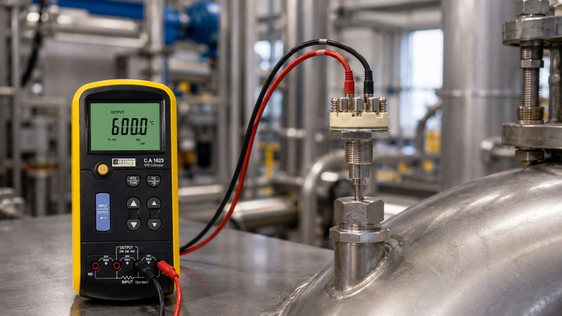
For a more accurate check, a temperature calibrator is useful. For thermocouples, a calibrator can either provide a defined temperature, for example via a dry block calibrator, or simulate a thermocouple signal or mV voltage. This makes it possible to distinguish whether the fault lies in the sensor, the cable or the display or input card.
A particularly helpful step is to simulate the thermocouple signal directly at the input of the evaluation device. If the calibrator outputs a defined thermocouple value and the display responds correctly, the input is probably parameterized correctly. If the error persists, the evaluation unit, cold junction compensation or parameterization should be checked. If the display is correct during simulation, but the real sensor measures incorrectly, the cause is more likely to be in the sensor, cable or installation.
In quality-relevant applications, the entire measuring chain should be considered. A calibrated sensor alone is not always sufficient if compensating cable, terminals, transmitter and display introduce additional errors. For reliable proof, testing or calibration of the complete measuring chain is therefore often useful.
Practical example: oven displays 40 °C too low
A company uses an industrial oven for heat treatment. The controller displays a temperature that is around 40 °C lower than the expected temperature. The process has not been changed, and the sensor was recently replaced. Initially, it is suspected that the new thermocouple is defective.
However, the check shows that a mechanically suitable sensor was installed, but electrically a different thermocouple type was supplied than originally used. The controller is still set to Type K, while the replacement sensor does not match the parameterization. In addition, a short piece of unsuitable copper cable was inserted in the control cabinet between the compensating cable and the controller.
A thermocouple calibrator is first used to check the controller input. When a Type K signal is simulated, the controller displays plausible values. This makes it clear that the input basically works. The sensor, cable and terminals are then checked. The wrong sensor type and the unsuitable intermediate wiring are corrected.
After replacement with a suitable thermocouple sensor and a continuous, type-compatible compensating cable, the display once again matches the comparison measurement. The example shows that an incorrect thermocouple value does not have to be caused by a defective sensor. Often, the combination of sensor type, cable and evaluation is the actual cause.
Which measuring instruments / products are suitable?
For selecting suitable sensors, ICS Schneider Messtechnik offers the category temperature sensors / temperature probes. There you will find, among other things, resistance thermometers, Pt100/Pt1000 sensors, thermocouples, cable sensors, infrared sensors as well as temperature transmitters and accessories. For applications with high temperatures, short response times or flexible measuring points, thermocouples are often a suitable solution.
If thermocouples are to be selected specifically, the category thermocouples is useful. When selecting a device, thermocouple type, measuring range, design, thermowell, sheath material, measuring junction design, connection head, cable type and required response time should be assessed together. Especially with replacement sensors, it is important that the new sensor not only fits mechanically, but also electrically belongs to the existing system.
Process calibrators and electrical calibrators are suitable for testing and troubleshooting. Especially with thermocouples, a calibrator that can measure or simulate various thermocouple types and mV signals is helpful. This makes it possible to check whether display, controller, data logger or PLC input respond correctly to the thermocouple type.
For calibrating the sensors themselves, temperature calibrators or dry block calibrators can be useful. They generate a defined temperature in which the sensor can be checked. For quality-relevant applications, it should always be considered whether only the sensor or the entire measuring chain including cable, transmitter and display needs to be checked.
If a thermocouple is converted into a 4–20 mA signal via a temperature transmitter, the electrical output side should also be checked. The UPS4E loop calibrator helps to measure and simulate mA signals and to identify scaling errors at PLC analog inputs or control systems.
| Product / area | Typical use | Particularly relevant for |
|---|---|---|
| Temperature sensors / temperature probes | Selection of suitable temperature sensors for industry, process, laboratory and service | Thermocouples, Pt100/Pt1000, cable sensors, screw-in sensors, surface and air sensors |
| Thermocouples | Temperature measurement with Type K, J, T, N and other thermocouple types | High temperatures, fast response times, furnace construction, mechanical engineering and test benches |
| Process calibrators / electrical calibrators | Simulation and testing of thermocouple, mV, current and voltage signals | Troubleshooting on displays, controllers, data loggers, PLC inputs and transmitters |
| Temperature calibrators | Testing temperature sensors at defined temperatures | Comparison measurement, calibration, quality assurance and service |
| UPS4E loop calibrator | Testing of 4–20 mA signals downstream of temperature transmitters | PLC scaling, signal testing, commissioning and troubleshooting current loops |
Conclusion: always check the entire measuring chain when thermocouple values are incorrect
When a thermocouple measures incorrectly, the sensor is only one possible cause. Errors are just as often found in the sensor type, compensating cable, polarity, terminal point, cold junction compensation, installation position, thermal coupling, EMC environment or parameterization of the evaluation unit. Replacing the sensor too quickly therefore often does not solve the problem permanently.
The most important recommendation is: always consider thermocouple measurements as a complete measuring chain. Sensor, cable, connector, terminals, input card, display, transmitter and installation location must match. Especially with replacement sensors and retrofit projects, it should be checked whether the new sensor really corresponds electrically to the original thermocouple type.
Comparison measurements and temperature calibrators are particularly helpful for troubleshooting. They show whether the deviation arises in the process, sensor, cable or evaluation. For thermocouples with a 4–20 mA transmitter, the current loop should also be checked so that sensor errors are not confused with scaling or wiring errors.
FAQ: Frequently asked questions about incorrect thermocouple readings
Why does my thermocouple measure incorrectly?
Common causes include a wrong thermocouple type, wrong compensating cable, reversed polarity, poor thermal coupling, insufficient immersion depth, faulty cold junction compensation, EMC interference, cable break or an incorrectly parameterized display or PLC.
How can I identify a wrong thermocouple type?
A wrong thermocouple type often shows a value that appears plausible but is permanently incorrect. Check the marking on the sensor, connector identification, compensating cable and the setting in the controller or data logger. Sensor and evaluation device must use the same thermocouple type.
Can a Type K thermocouple be replaced by Type J?
Only if the evaluation is also changed accordingly and the temperature range and application are suitable for the new type. Type K and Type J have different characteristic curves. If a Type J sensor is operated at a Type K input, incorrect temperature values will result.
Why is the compensating cable so important?
With thermocouples, the compensating cable is part of the measuring chain. It must match the thermocouple type. Incorrect cable materials or unfavorable transitions can generate additional thermoelectric voltages and thereby falsify the measured value.
What happens if positive and negative are reversed?
If the polarity is reversed, the display can react very incorrectly. The measured value can move in the wrong direction or appear implausible during temperature changes. Therefore, polarity, connectors and terminals should be checked during every troubleshooting process.
Why does the thermocouple show temperatures that are too low?
Values that are too low can be caused by wrong sensor type, poor thermal coupling, heat dissipation through the sensor, insufficient immersion depth, wrong compensating cable or incorrect parameterization. In surface measurements, insufficient thermal contact is often the cause.
Why does the thermocouple value fluctuate?
Fluctuating values are often caused by loose terminals, cable break, damaged cable, EMC coupling, poor shielding or potential problems. If the fluctuation is related to motor starts, frequency converters or heater controllers, the electrical environment should be checked.
What does cold junction compensation mean?
Cold junction compensation takes into account the temperature at the connection point of the thermocouple. Since a thermocouple generates a voltage depending on the temperature difference, the evaluation unit must know this connection point temperature or compensate it internally. Errors in this compensation lead to incorrect temperature values.
Is a grounded or ungrounded thermocouple better?
That depends on the application. Grounded thermocouples often respond faster and have good thermal contact. Ungrounded thermocouples are better electrically isolated and can be advantageous in the case of EMC or potential problems. The selection should be based on process dynamics and the electrical environment.
How do you check a thermocouple?
A thermocouple can be assessed by visual inspection, cable testing, comparison measurement and testing with a temperature calibrator. Simulating a thermocouple signal at the input of the evaluation device is particularly informative. This makes it possible to determine whether the fault lies in the sensor, cable or evaluation.
Can you check a thermocouple with a multimeter?
A multimeter can provide indications, for example of an interruption or rough mV signals. However, this is often not sufficient for reliable testing. A thermocouple calibrator that can measure or simulate suitable thermocouple types and mV signals is better.
Why is the installation position so important?
The thermocouple measures the temperature at its measuring junction. If this point is not representative of the process, the displayed value will not match the desired temperature. Incorrect installation position, insufficient immersion depth, poor surface contact or heat dissipation can cause significant errors.
What should be considered when using thermocouples for surface measurements?
The sensor needs good thermal contact with the surface. Loosely attached sensors, air gaps, uneven surfaces or strong heat dissipation through the cable falsify the measurement. Depending on the application, special surface sensors, spring-loaded sensors, strap-on sensors or thermal paste may be useful.
When should a temperature transmitter be used?
A temperature transmitter is useful when the thermocouple signal needs to be transmitted over longer distances, protected against interference or converted into a robust standard signal such as 4–20 mA. It can also handle cold junction compensation, linearization and diagnostic functions.
How do you check a 4–20 mA signal from a temperature transmitter?
The 4–20 mA signal is checked with a loop calibrator or a suitable measuring instrument. The current value is compared with the expected temperature value. In addition, defined mA values can be simulated to check PLC scaling and control system display independently of the sensor.
When should a thermocouple be replaced?
A thermocouple should be replaced if it is mechanically damaged, there is a cable break, the insulation is defective, significant drift has been detected or the comparison measurement shows an unacceptable deviation. Before replacement, however, it should be checked whether cable, connection and parameterization are the actual cause.