


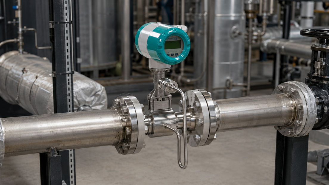
Several proven measuring principles are available for measuring steam flow in industrial plants. Vortex flowmeters and differential pressure measurements using orifice plates, nozzles, Venturi tubes or Pitot tubes are particularly common. Both methods are generally suitable for saturated and superheated steam, but differ significantly in terms of measuring range, pressure loss, installation effort and maintenance.
A vortex flowmeter usually forms a compact measuring point in which flow, temperature and, depending on the version, pressure are measured by one device. A differential pressure measurement, by contrast, consists of several components: the primary flow element, pressure tapping points, impulse lines, a valve manifold, the differential pressure transmitter and, where applicable, a separate flow computer.
Which principle is more economical and technically suitable therefore depends on more than the required accuracy. The minimum and maximum steam flow, nominal pipe size, available installation space, permissible pressure loss and whether an existing differential pressure measuring section is already installed are also decisive.
Table of contents
- How do the measuring principles differ?
- How does vortex flow measurement work?
- How does differential pressure measurement work?
- Direct comparison of vortex and differential pressure measurement
- Which principle causes greater pressure loss?
- Measuring range and part-load behaviour
- Pressure and temperature compensation for steam
- Straight pipe runs and installation
- What must be considered with wet steam?
- Costs, maintenance and retrofit
- Practical example of steam measurement
- When is each measuring principle suitable?
- Which measuring instruments / products are suitable?
- Conclusion
- Frequently asked questions
How do the measuring principles differ?
With vortex measurement, a regular vortex pattern is generated directly inside the pipe. Within the permissible measuring range, the frequency of these vortices has a fixed relationship to the flow velocity. The transmitter uses this value to determine the volumetric flow rate and calculates the mass flow rate using the steam density.
Differential pressure measurement, by contrast, generates a pressure difference at a defined restriction or flow obstruction. The differential pressure transmitter measures the difference between the high-pressure and low-pressure sides. The flow rate is then calculated from the differential pressure and the physical properties of the steam.
A significant difference lies in the design of the measuring point. With the vortex principle, the measuring body, sensor system and transmitter are located directly on the flowmeter. With differential pressure measurement, the primary element and differential pressure transmitter are functionally separated. This allows the system to be configured more flexibly, but also introduces additional potential sources of error and maintenance.
How does vortex flow measurement work?
A fixed bluff body is located inside the measuring tube of a vortex flowmeter. Downstream of this body, vortices are alternately shed from both sides. This flow pattern, known as a Kármán vortex street, generates periodic pressure fluctuations that are detected by a sensor.
The vortex frequency is proportional to the average flow velocity. Using the known geometry of the measuring tube, the instrument calculates the operating volumetric flow rate. To provide an output in kilograms per hour or tonnes per hour, the current steam density must also be taken into account.
Vortex flowmeters have no moving parts. Mechanical wear is therefore low. At the same time, the measuring principle requires a sufficiently high flow velocity and stable vortex formation. At very low flow rates, the measuring signal becomes weak and can no longer be reliably distinguished from vibrations or other interference.
A vortex instrument should therefore not be selected solely according to the nominal size of the existing pipeline. The minimum, normal and maximum mass flow rates are decisive. In an oversized pipeline, a smaller measuring cross-section may be necessary to ensure that a sufficiently high flow velocity is achieved even at part load.
How does differential pressure measurement work?
With differential pressure measurement, a primary element creates a defined change in flow velocity. Typical primary elements include:
- Orifice plates
- Flow nozzles
- Venturi tubes
- Single-hole or multi-hole Pitot tubes
The restriction increases the flow velocity while reducing the static pressure. The resulting differential pressure is transmitted to a differential pressure transmitter through two pressure tapping points and impulse lines.
In simplified terms, the following relationship applies:
Flow rate ∝ √(differential pressure / density)
The flow rate therefore does not increase linearly with the differential pressure. If the flow rate doubles, the differential pressure increases to approximately four times its previous value. This quadratic relationship is particularly important at low flow rates because the measured differential pressure decreases very rapidly in this range.
The accuracy of a differential pressure measurement does not depend solely on the differential pressure transmitter. The calculation and manufacture of the primary element, the internal pipe diameter, the edge quality of an orifice plate, the position of the pressure tapping points, the impulse lines and correct density compensation are equally important.
Direct comparison of vortex and differential pressure measurement
| Criterion | Vortex flow measurement | Differential pressure measurement |
|---|---|---|
| Measuring point design | Compact flowmeter, in some cases with integrated pressure and temperature measurement | Primary element, pressure tapping points, impulse lines, valve manifold and differential pressure transmitter |
| Suitable media | Steam, gases and many liquids | Steam, gases and liquids, depending on the primary element |
| Pressure loss | Present, but usually lower than with a conventional orifice plate | Highly dependent on the primary element; comparatively high with orifice plates |
| Part-load behaviour | Good measuring range with correct sizing, but a defined minimum flow is required | Differential pressure decreases quadratically at low flow rates |
| Maintenance effort | No impulse lines and no moving parts | Pressure tapping points, lines, condensate pots and valve manifold must be inspected |
| Large nominal pipe sizes | Technically possible, but instrument costs increase with nominal size and pressure rating | Often economical, particularly with an orifice plate or averaging Pitot tube |
| Retrofit | The pipeline must be opened and adapted for the complete measuring instrument | Existing primary elements and pressure tapping points can often continue to be used |
| Density compensation | Integrated into the instrument depending on the version | Additional pressure and temperature measurement or an external flow computer is required |
Which principle causes greater pressure loss?
Every component installed in a pipeline that influences the flow causes a permanent pressure loss. In a vortex flowmeter, this is mainly caused by the bluff body and the geometry of the measuring tube. With correct sizing, the pressure loss is often lower than with a conventional orifice plate.
No universally valid statement can be made for differential pressure measurement because the primary elements differ considerably. An orifice plate causes a relatively high permanent pressure loss. A nozzle or Venturi tube recovers a larger proportion of the static pressure. Averaging Pitot tubes can also operate with a comparatively low pressure loss.
For steam, pressure loss is not only a technical but also an economic criterion. An unnecessarily high pressure drop must be compensated for by the steam generator and may reduce the usable pressure reserve at the consumer. With continuously high steam flow rates, the ongoing energy costs can therefore be more important than the original purchase price of the measuring point.
Measuring range and part-load behaviour
With strongly fluctuating steam consumption, a correctly sized vortex measurement often offers advantages. The required minimum flow must still be achieved at the lowest operating flow rate. If the instrument is selected too large, it may drop to zero or display unstable values at part load.
With differential pressure measurement, the limitation results from the quadratic relationship between flow rate and differential pressure. If the flow rate falls to 10 percent of the design value, the differential pressure is only approximately 1 percent of the maximum differential pressure. Small zero-point shifts, unequal liquid columns or temperature effects have a particularly strong impact in this range.
A modern differential pressure transmitter can detect very small pressure differences and provide large turndown ratios. However, this does not eliminate the physical limitation of the entire measuring point. The primary element, pipeline data and uncertainty of pressure transmission remain part of the measuring chain.
Pressure and temperature compensation for steam
The directly measured volumetric flow rate is usually not sufficient for meaningful steam consumption measurement. Steam density changes significantly with pressure and temperature. For billing, energy monitoring or plant balancing, the mass flow rate in kilograms or tonnes per hour is therefore normally required.
With saturated steam, there is a defined relationship between pressure and saturation temperature. If dry saturated steam is actually present, the density can therefore generally be calculated from either of these process variables. Integrated temperature compensation may be sufficient for such an application.
With superheated steam, both pressure and temperature must be taken into account. Otherwise, the calculation will use an incorrect density. This applies to both vortex and differential pressure measurements.
A vortex measuring point with integrated pressure and temperature compensation reduces the number of individual instruments and associated measurement errors. With conventional differential pressure measurement, differential pressure, static pressure and temperature are frequently measured separately and combined in a flow computer or process control system.
If not only the mass flow rate but also the thermal power is to be determined, the specific enthalpy of the steam must also be taken into account. For a net heat calculation, the temperature and energy content of the returned condensate may also be relevant.
Straight pipe runs and installation
Both measuring principles require a flow profile that is as stable and well defined as possible. Bends, control valves, reducers, expanders and partially open shut-off valves can generate swirl or asymmetrical velocity profiles.
For the SITRANS FX300, a minimum upstream straight run of 20 × DN and a downstream straight run of 5 × DN are specified under normal conditions. Longer straight runs or additional measures may be required downstream of several bends, control valves or major changes in pipe cross-section.
Differential pressure measurement also requires defined upstream and downstream straight runs. The required lengths depend, among other factors, on the type of primary element, the diameter ratio, the upstream pipeline geometry and the applicable standard. For a standard-compliant orifice plate, the actual internal pipe diameter and the geometry of the orifice plate must also be known.
Correct pressure transmission is an additional consideration when measuring steam. Comparable condensate columns must be created on both sides of the differential pressure transmitter. Differences in filling height or temperature generate an additional hydrostatic differential pressure and therefore a measurement error. Pressure tapping points, condensate pots and impulse lines must consequently be designed symmetrically and commissioned correctly.
What must be considered with wet steam?
Wet steam consists of a mixture of steam and liquid droplets. As a result, the actual density and energy content no longer correspond to the values for dry saturated steam. Standard pressure or temperature compensation does not automatically detect the steam quality.
With vortex measurement, liquid droplets and fluctuating steam quality can affect vortex formation and the sensor signal. Condensate hammer and high liquid content can also cause mechanical loads.
With differential pressure measurement, two-phase flow likewise causes additional uncertainty. Conditions in the impulse lines may also change. An orifice plate therefore does not automatically make wet steam more reliably measurable.
If significant condensate occurs, steam separators, drainage, pipeline gradient and the operating condition should first be checked. For reliable energy or billing measurements, steam quality must be considered during the design process.
Costs, maintenance and retrofit
For a new measuring point, a vortex flowmeter is often the more compact solution. Installation work is essentially limited to fitting the measuring instrument, making the electrical connection and, where applicable, connecting external temperature sensors. Separate impulse lines and condensate pots are not required.
A differential pressure measuring point may initially appear less expensive, particularly when a simple orifice plate is used. For a realistic cost comparison, however, pressure tapping points, valve manifold, pipework, condensate pots, differential pressure transmitter, installation and flow calculation must also be included.
For very large pipelines or high pressure ratings, differential pressure measurement can offer economic advantages. A complete inline vortex instrument becomes larger and more expensive as the nominal size and pressure class increase, whereas an orifice plate or Pitot tube can be integrated into an existing pipeline comparatively easily.
For retrofit applications, the existing plant design is decisive. If a calculated orifice plate with functional pressure tapping points is already installed, replacing an older differential pressure transmitter may be an economical modernisation. If the impulse lines are corroded, blocked or no longer documented, converting to a compact vortex instrument may be more beneficial in the long term.
The maintenance effort also differs. A vortex instrument has no moving parts and no external impulse lines. With differential pressure measurement, the pressure tapping points, condensate pots, shut-off valves, equalising valves and lines must be inspected regularly. In the case of an orifice plate, the sharp upstream edge can also be altered by erosion, corrosion or deposits.
Practical example: Measuring a strongly fluctuating steam supply
A production plant is supplied with saturated steam. The maximum mass flow rate is 10 t/h. During normal operation, 5 t/h is required, while consumption falls to 2.5 t/h during off-peak periods. For differential pressure measurement, a differential pressure of 250 mbar is designed at the maximum flow rate.
Due to the quadratic relationship, the following differential pressures result:
- At 10 t/h or 100 percent flow: 250 mbar
- At 5 t/h or 50 percent flow: 62.5 mbar
- At 2.5 t/h or 25 percent flow: 15.625 mbar
Although 25 percent of the maximum steam flow is still present, the differential pressure is only 6.25 percent of the measuring range upper value. If the differential pressure is output linearly as a 4–20 mA signal, this corresponds to only:
4 mA + 6.25% × 16 mA = 5.0 mA
Only after square-root extraction does a flow rate of 25 percent correspond to an output signal of:
4 mA + 25% × 16 mA = 8.0 mA
During commissioning, it must therefore be clearly defined whether the differential pressure transmitter outputs a linear differential pressure signal or an already square-root-extracted flow signal. Performing square-root extraction twice, once in the transmitter and once in the PLC, would result in significantly incorrect measured values.
A Druck UPS4E loop calibrator can be used to check the 4–20 mA signal, loop power supply and scaling of the PLC input. The hydraulic or pneumatic test of the differential pressure transmitter and inspection of the primary element remain separate operations.
For the plant described, a correctly sized vortex instrument may offer advantages if the measurement remains safely above the minimum flow even at 2.5 t/h. If a documented and functional orifice plate is already installed, a modern differential pressure transmitter with correct square-root extraction and density compensation may instead be the more economical solution.
When is each measuring principle suitable?
Vortex measurement is often more suitable when:
- a new, compact steam measuring point is being installed,
- pressure loss must be limited,
- the steam flow fluctuates considerably,
- mass flow or energy is to be output directly,
- impulse lines and condensate pots are to be avoided,
- sufficient straight pipe runs and minimum flow velocity are available.
Differential pressure measurement is often more suitable when:
- a primary element and suitable pressure tapping points are already installed,
- very large nominal pipe sizes or high pressure ratings are involved,
- a specific standardised primary element is prescribed,
- the measuring range is relatively constant,
- the differential pressure transmitter must remain easily accessible during plant operation,
- the primary element must be adapted to special process conditions.
The selection should always be based on the actual operating data. A general decision based solely on nominal pipe size or maximum flow rate frequently results in an oversized measuring instrument and therefore problems at part load.
Which measuring instruments / products are suitable?
SITRANS FX300 vortex flowmeter
The SITRANS FX300 is suitable for measuring the flow of saturated steam, superheated steam, gases and liquids. The instrument is available in various designs and, depending on the version, can measure temperature or pressure and temperature for density compensation.
Integrated temperature compensation can be used for saturated steam applications. For superheated steam, a version with pressure and temperature compensation is required. The instrument can calculate mass, standard volume and energy and can be integrated into the process control system via 4–20 mA or HART.
WIKA DPT-20 differential pressure transmitter
The WIKA DPT-20 is designed for differential pressure and flow measurements in combination with a suitable primary flow element. Freely scalable measuring ranges and various output signals allow adaptation to existing measuring points.
For a complete steam flow measurement, the primary element, maximum differential pressure, static line pressure, valve manifold, impulse lines and density compensation must be designed together. The suitability of the transmitter alone does not indicate the accuracy of the complete flow measuring point.
Druck UPS4E loop calibrator
The Druck UPS4E is suitable for testing electrical signal transmission. It can measure 4–20 mA outputs, simulate input signals for PLCs or control systems, and check scaling and loop power supply. Testing the electrical signal does not, however, replace the flow-related inspection or pressure calibration of the measuring point.
Conclusion: Vortex for compact measuring points, differential pressure for flexible and existing systems
For new steam measuring points with changing load conditions, limited maintenance requirements and direct mass or energy calculation, a vortex flowmeter is often the more practical solution. The measuring point is compact, requires no external impulse lines and usually causes less pressure loss than a conventional orifice plate.
Differential pressure measurement remains attractive, particularly for large pipelines, high pressure ratings, standardised measuring sections and existing primary elements. It is flexible and has been established for decades, but requires careful design of the complete measuring chain.
The actual minimum and maximum steam flow, steam condition, pipeline geometry and permissible pressure loss are decisive. A correctly sized measuring point is more important than the fundamental choice between vortex and differential pressure measurement.
Frequently asked questions about vortex and differential pressure measurements for steam
Does a vortex flowmeter measure mass flow directly?
The vortex measuring principle initially detects the flow velocity or operating volumetric flow rate. The mass flow rate is calculated using the current steam density. Pressure and temperature or the saturated steam condition must therefore be taken into account correctly.
Is a differential pressure transmitter alone sufficient for steam flow measurement?
No. A calculated primary element, pressure tapping points, impulse lines, a valve manifold and a flow calculation are also required. For mass flow or energy measurement, the physical properties of the steam must additionally be considered.
Does a vortex flowmeter cause no pressure loss?
A vortex instrument also causes a permanent pressure loss due to its bluff body. However, this is often lower than with a conventional orifice plate. The actual value depends on the nominal size, design, flow rate and operating density.
Which measuring principle is more suitable for low steam flow rates?
This depends on the sizing. A vortex instrument requires a minimum flow velocity for stable vortex formation. With differential pressure measurement, the differential pressure decreases quadratically as the flow rate falls. Both systems must therefore be sized according to the actual minimum flow rate.
Is temperature measurement sufficient for compensating saturated steam?
With dry saturated steam, there is a defined relationship between pressure and temperature. The density can therefore generally be determined from either of these variables. With superheated steam, however, both pressure and temperature must be taken into account.
Which measuring principle is more suitable for wet steam?
Neither principle automatically compensates for steam quality. Liquid droplets can influence both vortex and differential pressure measurement. If a relevant proportion of wet steam is present, steam quality, drainage and, where necessary, upstream separation must be considered.
Can an existing orifice plate continue to be used?
This is possible if its geometry, material, pressure tapping points and pipeline data are known and in good condition. Wear, deposits or a damaged upstream edge alter the flow coefficient and may require recalculation or replacement.
Which information is required for sizing?
At minimum, the required information includes the medium and steam condition, minimum, normal and maximum mass flow rates, operating pressure, operating temperature, nominal pipe size, internal pipe diameter or wall thickness, material, pressure rating, available upstream and downstream straight runs, permissible pressure loss, required accuracy, output signal and, where applicable, requirements relating to explosion protection or functional safety.