


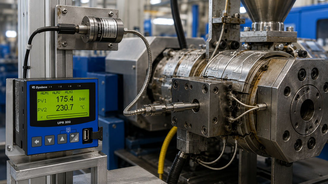
In extrusion, injection moulding and polymer processing systems, both melt pressure and the actual temperature of the polymer melt affect process stability and product quality. If the two measured variables are recorded separately or at measuring points located far apart, relationships between pressure changes, material temperature and machine condition can often only be assessed to a limited extent.
A melt pressure sensor with an integrated thermocouple combines pressure and temperature measurement at one common process connection. This allows pressure and temperature to be measured almost at the same measuring point and evaluated together in an indicator, controller or machine control system.
The combined design saves an additional mounting port and enables a compact measuring point. However, it does not replace a separate melt temperature sensor in every application. The decisive factors are the position of the temperature measuring point within the sensor and how far it actually extends into the melt flow.
Table of contents
- Why measure pressure and temperature together?
- How does a combined melt pressure sensor work?
- How is melt pressure measured?
- How is melt temperature measured?
- Combined sensor or separate temperature probe?
- The correct installation position in the extruder
- Response time and significance of temperature measurement
- Output signals and signal processing
- Typical wiring errors
- Evaluating pressure and temperature together
- Practical example on an extrusion line
- Important selection criteria
- Which measuring instruments / products are suitable?
- Conclusion
- Frequently asked questions
Why measure pressure and temperature together?
The pressure in the polymer melt is influenced, among other factors, by material viscosity, throughput, screw speed, die geometry and the flow resistance of screen changers, filters and nozzles. The melt temperature in turn affects the viscosity and therefore also the pressure required.
As the temperature rises, the viscosity of many thermoplastic materials decreases. Under otherwise identical conditions, this can reduce the melt pressure. Conversely, a melt that is too cold or insufficiently plasticised can result in higher pressures.
Considering both measured variables at the same time therefore helps distinguish between different causes. Rising pressure with a largely constant temperature may, for example, indicate increasing flow resistance. If pressure and temperature change simultaneously, changes in the material, heating output, throughput or shear stress may also be involved.
Typical applications of combined measurement include:
- Monitoring melt pressure upstream of the die, nozzle or screen changer
- Detecting filter and screen contamination
- Checking the actual melt temperature
- Stabilising extrusion and dosing processes
- Protecting the machine, tooling and sensors against overpressure
- Recording process values for quality documentation
How does a combined melt pressure sensor work?
A combined melt pressure sensor contains two electrically separate measuring systems. Pressure is measured via a flush-mounted diaphragm. Temperature is measured using an integrated thermocouple or, depending on the sensor version, a resistance thermometer.
Both signals are routed out of the process through a common sensor connection or cable housing. However, they are evaluated through separate electrical channels. The pressure output may, for example, be provided as an mV/V, 0–10 V or 4–20 mA signal, while the thermocouple supplies a thermoelectric voltage.
A combined sensor therefore does not automatically provide one common output signal for both measured variables. The indicator, controller or PLC must have suitable inputs for the respective pressure output and the temperature sensor type used.
How is melt pressure measured?
The hot polymer melt acts directly on the flush-mounted measuring diaphragm of the sensor. The diaphragm movement is transmitted through a closed transmission system to a strain gauge measuring element. This element is located at a greater distance from the hot process.
Depending on the design, the sensor has a rigid stem or an additional flexible capillary connection between the sensor stem and the electronics or strain gauge housing. The flexible version protects the sensitive measuring element against high ambient temperatures and facilitates installation in difficult-to-access locations.
The diaphragm must be flush with the inner wall of the process bore. If it is installed too deeply, polymer can accumulate in front of the diaphragm and harden. If the sensor protrudes too far into the melt channel, the diaphragm and stem may be damaged by flow forces or during installation.
How is melt temperature measured?
Many combined Dynisco melt pressure sensors use a type J thermocouple. It generates a small thermoelectric voltage that depends on the temperature difference between the measuring junction and the reference junction. The connected controller or measuring input must therefore be configured for a type J thermocouple and provide suitable cold-junction compensation.
The temperature is measured at the same process connection as the pressure. However, this does not automatically mean that the exact average temperature of the entire melt flow is recorded. A measuring point close to the wall or with only a small immersion depth can be influenced more strongly by the temperature of the extruder barrel or die.
The following factors are therefore important when assessing the measurement:
- Position of the thermocouple within the sensor design
- Immersion depth of the temperature measuring point
- Flow velocity of the melt
- Temperature difference between the melt and the machine wall
- Heat conduction through the stem and process connection
- Response time of the temperature sensor
Combined measurement is very useful for trend monitoring and correlating pressure and temperature changes. If, however, a temperature profile across the pipe cross-section is required or the core temperature of the melt is to be determined as accurately as possible, a separate immersion-type melt temperature probe may be more suitable.
Combined sensor or separate temperature probe?
| Criterion | Melt pressure sensor with thermocouple | Separate melt temperature probe |
|---|---|---|
| Installation effort | Only one common process connection is required | An additional mounting bore is required |
| Measuring position | Pressure and temperature at the same connection | Temperature measuring point can be positioned independently |
| Immersion depth | Defined by the sensor design | Fixed, adjustable or retractable depending on the version |
| Temperature profile | Only one defined measuring point | With an adjustable probe, measurement across part of the cross-section may be possible |
| Space requirement | Compact solution | Two separate measuring points |
| Replacement | If a fault occurs, the entire sensor unit often has to be removed | Pressure and temperature sensors can be replaced independently |
| Typical application | Process monitoring and compact machine measuring points | More representative melt temperature measurement and temperature profiles |
The correct installation position in the extruder
The installation position determines which process changes the sensor can detect. A sensor upstream of the screen changer, for example, records the pressure generated by the screw and the increasing resistance of the filter. An additional measuring point downstream of the screen changer allows the differential pressure across the filter to be determined.
A measurement directly upstream of the die or nozzle, by contrast, shows the conditions under which the melt enters the shaping component. This position is often particularly relevant to product quality, dimensional accuracy and process repeatability.
The sensor should be installed in a well-flushed area wherever possible. Dead spaces, deposit zones and locations with highly variable flow can lead to delayed or non-representative measured values.
Before installation, the mounting bore, thread, sealing surface and bore depth must be checked. Hardened polymer residues must be removed using suitable cleaning tools. The sensitive diaphragm must not be mechanically cleaned or touched with hard tools.
Response time and significance of temperature measurement
Pressure changes are generally detected more quickly by a melt pressure sensor than temperature changes. The pressure diaphragm responds immediately to the process pressure, whereas the temperature measuring point must first thermally adapt to the melt.
Following a rapid change in throughput, speed or heating output, the pressure reading may therefore already change significantly while the displayed temperature remains almost constant. This is not necessarily a sensor fault, but may result from the different dynamic behaviour of the two measured variables.
For control functions, the response time, filtering and sampling rate of the measuring channels should therefore be considered. Excessive digital damping can conceal critical pressure peaks. A completely undamped temperature indication, by contrast, may display small electrical interference unnecessarily strongly.
Output signals and signal processing
Melt pressure sensors and transmitters are available with different electrical outputs. The choice depends on the cable length, existing evaluation equipment and interference environment.
| Signal | Characteristics | Typical evaluation |
|---|---|---|
| mV/V | Unamplified strain gauge signal; power supply and evaluation by an external amplifier are required | Dynisco indicator, measuring amplifier or dedicated controller input |
| 0–10 V | Amplified voltage signal, easy to evaluate, but more sensitive to voltage drops and interference over long cable runs | PLC, indicator or machine controller with voltage input |
| 4–20 mA | Interference-resistant signal transmission, particularly suitable for longer cable runs | PLC, process indicator or controller with current-loop input |
| Thermocouple | Small temperature-dependent thermoelectric voltage; suitable extension cable and cold-junction compensation are required | Type J thermocouple input or suitable temperature transmitter |
| RTD | Resistance change, depending on the version in 2-, 3- or 4-wire configuration | Pt100 input, temperature transmitter or controller |
With a combined sensor, the pressure and temperature channels must be scaled and processed separately. A sensor with a 4–20 mA pressure output and type J thermocouple, for example, requires an analogue current input for the pressure and a thermocouple input for the temperature.
The 4–20 mA pressure signal can be measured using a Druck UPS4E loop calibrator or simulated to test the downstream indicator or PLC. A suitable thermocouple simulator is additionally required to test the thermocouple channel.
Typical wiring errors
With combined sensors, faults often occur not at the process connection but when assigning the individual electrical conductors. The pressure supply, pressure output and thermocouple connections must not be confused.
The polarity of a thermocouple must also be observed. If the positive and negative conductors are reversed, the displayed temperature may move in the wrong direction during heating or show clearly implausible values.
An extension or thermocouple cable suitable for the thermocouple type should be used between the thermocouple and the evaluation instrument. Changing to ordinary copper conductors can generate additional thermoelectric voltages and therefore measurement errors.
Other typical errors include:
- incorrect thermocouple type configured in the controller,
- missing or duplicated cold-junction compensation,
- unsuitable cable routing next to motor or heating cables,
- cable screens connected incorrectly at one or several points,
- incorrect scaling of the pressure signal,
- an unsuitable transmitter supply voltage,
- missing galvanic isolation where different earth potentials are present.
Evaluating pressure and temperature together
The greatest benefit of a combined sensor is achieved when both measured values are evaluated together and recorded over time. Individual instantaneous values only show the current condition. Trends, by contrast, reveal gradual changes and recurring relationships.
| Observation | Possible cause |
|---|---|
| Pressure rises while temperature remains largely constant | Screen or filter is becoming blocked, die cross-section is changing or throughput is increasing |
| Pressure falls while temperature rises | Viscosity decreases due to the higher melt temperature |
| Pressure and temperature fluctuate periodically | Irregular material feed, unstable screw speed or fluctuating heating control |
| Temperature rises as speed increases | Additional heating caused by shear and mechanical energy |
| Pressure peaks without a noticeable temperature change | Temporary blockage, material inhomogeneity or unstable conveying |
These correlations are indications rather than definitive diagnoses. Material properties, machine design, measuring position and operating condition must always be considered as well.
Practical example: Pressure increase upstream of a screen changer
A combined melt pressure transmitter is installed upstream of the screen changer on an extrusion line. The pressure measuring range is 0 to 350 bar and the pressure output is 4–20 mA. The integrated type J thermocouple simultaneously measures the temperature at the measuring point.
During normal operation, 175 bar and 230 °C are measured. The corresponding current value of the pressure channel is:
4 mA + (175 bar / 350 bar × 16 mA) = 12 mA
During further operation, the pressure gradually rises from 175 to 260 bar, while the temperature remains almost constant at approximately 230 °C. As neither the material throughput nor the screw speed has changed, the trend indicates increasing flow resistance at the screen.
Evaluating the two variables together prevents the pressure increase from being prematurely interpreted as the result of an excessively low melt temperature. A screen change can be planned in good time before an overpressure shutdown occurs or the process becomes unstable.
To test the downstream pressure channel, a current signal of 12 mA can first be simulated. The PLC or indicator must then display 175 bar. Further points, for example 4 mA for 0 bar and 20 mA for 350 bar, are then checked. The electrical simulation checks the scaling of the evaluation system, but does not replace pressure calibration of the sensor.
Important selection criteria
The sensor should not be selected solely according to the maximum extruder pressure. An unnecessarily large measuring range reduces the usable resolution in the normal operating range. At the same time, pressure peaks and the permissible overload must be considered.
The following information is particularly important for sizing:
- minimum, normal and maximum melt pressure,
- minimum and maximum process temperature,
- processed polymer and possible fillers or reinforcing materials,
- existing mounting thread and exact mounting bore,
- required stem length and flexible connection,
- required pressure output signal,
- thermocouple or RTD version,
- electrical connection and cable length,
- ambient temperature at the sensor housing,
- where applicable, requirements for explosion protection or functional safety.
The chemical and abrasive load on the measuring diaphragm must also be considered. Glass fibres, mineral fillers or aggressive additives can increase wear. The final suitability of the diaphragm and coating materials must therefore be assessed for the specific application.
Which measuring instruments / products are suitable?
Dynisco TDA 432/463 melt pressure sensor
The Dynisco TDA 432/463 combines an unamplified mV/V pressure signal with an integrated type J thermocouple. The series is suitable for measuring chains in which a compatible strain gauge amplifier, indicator or machine controller is already available.
Dynisco TDT 432/463 melt pressure transmitter
The Dynisco TDT 432/463 measures melt pressure and temperature at one process connection and provides the pressure as an amplified voltage signal. This allows the pressure channel to be connected directly to suitable voltage or controller inputs.
Dynisco TDT 432/463 F with 4–20 mA output
The Dynisco TDT 432/463 F combines pressure measurement via an interference-resistant 4–20 mA output with an integrated thermocouple. This version is particularly suitable for longer cable runs and direct integration into PLC and process control systems.
Separate Dynisco melt temperature sensors
The Dynisco melt temperature category includes thermocouple and RTD probes with different threads, designs and immersion depths. Separate probes are particularly useful when the temperature must be measured farther inside the melt flow, the immersion depth must be adjusted or a temperature profile is required.
Conclusion: Two measured variables at one compact process connection
A melt pressure sensor with an integrated thermocouple enables simultaneous monitoring of melt pressure and temperature at one common process connection. This saves installation space and makes it easier to correlate pressure changes with thermal process changes.
Particularly on extruders, screen changers, adapters and dies, combined measurement provides important information about material flow, filter condition and process stability. The prerequisites are a correctly machined mounting bore, correct selection of the pressure range and separate, technically correct evaluation of both signals.
For pure trend and process monitoring, the integrated temperature measurement is often sufficient. If a representative core temperature or a temperature profile is required, a separate immersion-type or adjustable melt temperature probe may be the better solution.
Frequently asked questions about melt pressure sensors with temperature measurement
Does a combined sensor output pressure and temperature through one common signal?
Usually not. The pressure channel and the thermocouple or RTD provide separate electrical signals. The evaluation instrument therefore requires two suitable inputs.
Does the integrated thermocouple measure the actual melt temperature?
It measures the temperature at its defined constructional measuring position. Depending on the immersion depth and heat conduction, the value may be influenced more strongly by the temperature close to the wall than with a probe extending deeply into the melt flow.
When is a separate melt temperature probe more suitable?
A separate probe is useful when a greater or adjustable immersion depth, measurement close to the centre of the flow or recording of a temperature profile is required.
Can a type J thermocouple be connected directly to any analogue input?
No. A type J thermocouple input or a suitable temperature transmitter is required. A normal voltage or current input generally does not provide the necessary linearisation and cold-junction compensation.
Why does the pressure channel show faster changes than the temperature channel?
The pressure acts directly on the measuring diaphragm. The temperature measuring point, by contrast, must first thermally adapt to the melt. The temperature channel therefore usually has a longer response time.
Can a 4–20 mA signal be tested without applying pressure to the sensor?
The scaling of the indicator or PLC can be tested by simulating a 4–20 mA signal. However, this only checks the electrical signal path. A defined pressure must be applied to test the sensor itself.
What can cause an incorrect temperature value even when the sensor is intact?
Common causes include reversed thermocouple conductors, an incorrectly configured sensor type, unsuitable extension cables, additional junctions or incorrect cold-junction compensation.
Which information is required for instrument selection?
The required information includes the pressure and temperature range, polymer or melt, fillers, mounting thread, bore geometry, stem and capillary length, required pressure signal, temperature sensor type, electrical connection, cable length and any explosion-protection or safety requirements.