


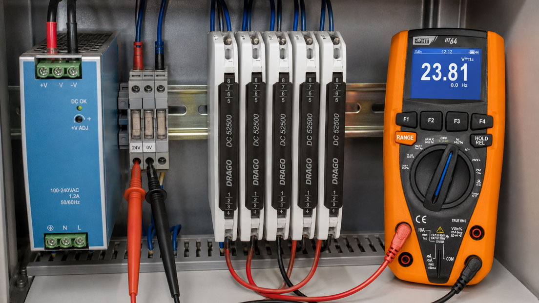
In machines and control cabinets, a 24 V DC power supply often supplies PLCs, HMIs, sensors, transmitters, relays, valves and communication modules simultaneously. During normal operation, the measured current consumption may be considerably lower than the rated current of the power supply. Nevertheless, the supply voltage may briefly collapse during start-up or during a particular machine cycle.
The cause is often not the total continuous current alone. Capacitive inputs, solenoid valves, contactors, operator panels and decentralised electronics may require considerably more current during start-up than during steady-state operation. Voltage drops across long cables, fuses, terminals and plug connections must also be taken into account.
A reliably dimensioned power supply must therefore cover more than just the sum of the rated currents. The actual load profile, the magnitude and duration of inrush currents, the power reserve, temperature behaviour, power distribution and short-circuit behaviour of the complete 24 V system are decisive.
Suitable power supplies and supplementary components can be found in the power supply section. Adjustable power supplies for development, testing and commissioning are grouped together under power supplies and laboratory power supplies.
Contents
- Correctly assigning rated voltage, current and power
- Systematically recording all 24 V loads
- Considering simultaneity and operating states
- Correctly assessing inrush and starting currents
- Capacitive loads and charging energy
- Assessing the power supply’s boost function
- How much power reserve is advisable?
- Calculating the voltage drop in 24 V cables
- Planning the 24 V distribution and conductor cross-section
- Correctly dimensioning fuses and selectivity
- Temperature derating and control-cabinet climate
- Parallel operation and future expansion
- Testing the supply under actual operating conditions
- Typical dimensioning errors
- Practical example: HMI restarts when valves switch
- Recommended dimensioning procedure
- Which products and solutions are suitable?
- Conclusion
- Frequently asked questions
Correctly assigning rated voltage, current and power
A typical control-cabinet power supply provides a regulated output voltage of 24 V DC. The specified rated current describes the current that the device can supply continuously under the specified operating conditions.
The electrical output power is calculated as follows:
P = U × I
A power supply with 24 V and 10 A therefore has a rated output power of:
24 V × 10 A = 240 W
For dimensioning purposes, the calculation should initially be based on current, since connected loads usually specify their current consumption at 24 V. However, with devices that have a wide supply-voltage range, it must be considered that the current consumption may increase at a lower voltage.
Efficiency is also relevant. The difference between input and output power is predominantly dissipated as heat inside the control cabinet. A power supply with an output power of 240 W and an efficiency of 92% generates approximately 21 W of power loss at rated load.
Systematically recording all 24 V loads
The basis of every dimensioning process is a complete load list. In addition to the obvious loads, small auxiliary devices are often overlooked, even though their combined consumption can represent a relevant load.
Typical 24 V loads include:
- PLCs and input/output modules,
- HMIs and industrial PCs,
- sensors and transmitters,
- signal converters and isolating amplifiers,
- Ethernet switches and fieldbus components,
- relays, contactors and interface modules,
- solenoid valves and brakes,
- warning lights and signal devices,
- fans and small DC motors,
- electronic circuit breakers and UPS modules.
At least the following data should be documented for each load:
| Specification | Significance for dimensioning |
|---|---|
| Rated current | Continuous load during normal operation |
| Maximum current | Highest current consumption during permissible operation |
| Inrush current | Short-term load during start-up |
| Duration of the load peak | Comparison with the power supply’s boost characteristic |
| Minimum permissible voltage | Limit for cable losses and voltage dips |
| Operating state | Simultaneous operation with other loads |
Simply adding the typical current consumption is not sufficient if the data sheet also specifies a higher maximum or inrush current.
Considering simultaneity and operating states
Not every load is active simultaneously throughout the complete machine cycle. Nevertheless, the simultaneity factor must not be set too low without justification.
Several operating states should be considered when calculating the load:
- start-up of the complete system,
- normal automatic operation,
- simultaneous switching of several valves,
- setup or manual operation,
- fault conditions and safe shutdown,
- restart following a power failure,
- maintenance using additional diagnostic equipment.
With eight solenoid valves, it is not necessarily necessary to calculate using eight simultaneously energised coils. However, if the operating sequence permits four valves to switch simultaneously, at least these four valves must be included.
Safety functions require particular attention. When an emergency stop is activated, several relays and valves may change state simultaneously. The resulting load condition may differ considerably from normal production operation.
Correctly assessing inrush and starting currents
Two different effects must be distinguished when considering inrush current:
- Input-side inrush current of the power supply: occurs when the internal capacitors on the AC side are charged and places a load on miniature circuit breakers, contactors or upstream UPS systems.
- Output-side inrush current of the loads: occurs on the 24 V side when input capacitors are charged or magnetic and mechanical loads are energised.
If several power supplies are switched on simultaneously through a main contactor, their input-side current peaks may trip a miniature circuit breaker even though the subsequent continuous load is uncritical.
On the output side, the following loads in particular may generate high starting currents:
- HMIs and industrial PCs,
- DC/DC converters,
- control electronics for frequency converters,
- communication devices with large input capacitors,
- solenoid valves, contactors and brakes,
- DC motors and fans.
Not only the peak value is decisive, but also its duration. A current peak of 20 A lasting only a few microseconds loads the power supply differently from 15 A lasting several hundred milliseconds.
Capacitive loads and charging energy
Many electronic loads contain capacitors at their inputs. These must first be charged during start-up. The theoretical charging current depends on the capacitance and voltage rise:
I = C × ΔU / Δt
The energy stored in the capacitor is:
E = ½ × C × U²
Several individually unremarkable devices can form a large total capacitance when switched on simultaneously. The power supply may then enter current-limiting mode. The output voltage rises more slowly or briefly drops.
Possible consequences include:
- the PLC restarts several times,
- the HMI remains stuck during the boot process,
- communication modules report undervoltage,
- relays energise and drop out again,
- several devices start with a delay or in an undefined sequence.
For large capacitive loads, the maximum load capacitance permitted by the power supply and the behaviour of its output voltage during start-up should be checked.
Assessing the power supply’s boost function
Many industrial power supplies can provide more than their rated current for a short period. Manufacturers use terms such as Power Boost, Dynamic Boost, Top Boost or short-circuit boost for these functions.
These functions must not be treated as equivalent. The following must be checked:
- magnitude of the additional current,
- permissible duration of the overload,
- recovery time between two boost operations,
- temperature range within which the boost is available,
- behaviour after the boost period has expired,
- behaviour under short-circuit and capacitive-load conditions.
A power supply with a rated current of 10 A and a boost current of 15 A may, for example, absorb a short load peak. However, it is not automatically suitable for a continuous operating current of 12 A.
Some power supplies briefly provide a particularly high fault current so that a downstream miniature circuit breaker can trip. This function is intended to support selectivity and must not be confused with a general continuous reserve.
How much power reserve is advisable?
A general reserve of approximately 20 to 30% is often practical for an initial design. However, it does not replace the assessment of the actual load peaks and temperature conditions.
The reserve serves several purposes:
- compensation for component tolerances,
- allowance for future expansion,
- lower continuous thermal loading,
- reserve for load peaks,
- allowance for ageing and deteriorating cooling conditions.
An excessively large power supply is not always optimal either. It requires more space, may have a higher input-side inrush current and may make it more difficult to provide selective protection for small branch circuits.
The reserve should therefore be derived from the specific project. It may be lower for an unchangeable series machine than for a modular control cabinet that may later be expanded with additional sensors and valves.
Calculating the voltage drop in 24 V cables
For direct current, the resistance of both the outgoing and return conductor must be taken into account. For a copper cable, the voltage drop can be calculated approximately as follows:
ΔU = 2 × l × I × ρ / A
Where:
- ΔU: voltage drop in volts,
- l: one-way cable length in metres,
- I: load current in amperes,
- ρ: specific resistance of copper, approximately 0.0178 Ω·mm²/m at 20 °C,
- A: conductor cross-section in mm².
Example:
- one-way cable length: 30 m,
- load current: 4 A,
- conductor cross-section: 1.5 mm².
This gives:
ΔU = 2 × 30 m × 4 A × 0.0178 Ω·mm²/m ÷ 1.5 mm² ≈ 2.85 V
With exactly 24.0 V at the power supply, only approximately 21.15 V theoretically reaches the load. Voltage drops across fuses, terminals and plug connections have not yet been included.
Whether this voltage is sufficient must be checked against the minimum permissible supply voltage of the load. The conductor resistance also increases with temperature.
Increasing the output voltage of the power supply may partially compensate for a known cable loss. However, nearby loads and loads operating at low current must not receive an impermissibly high voltage.
Planning the 24 V distribution and conductor cross-section
A star-shaped distribution or a distribution divided into functional groups is often more reliable than a long daisy-chain connection throughout the complete control cabinet or machine.
Suitable load groups include, for example:
- PLC and safety-related control equipment,
- sensors and analogue measuring equipment,
- HMI and communication equipment,
- relays and contactors,
- solenoid valves and other actuators.
Separating sensitive electronics from heavily switching actuators reduces mutual interference. A valve switching operation then does not directly cause the same voltage drop in the PLC supply cable.
For decentralised loads, larger conductor cross-sections, separate cables, a local power supply or a DC/DC converter may be more suitable than one long 24 V cable.
The conductor cross-section must be dimensioned with regard to the voltage drop, current-carrying capacity and short-circuit protection.
Correctly dimensioning fuses and selectivity
A fuse does not automatically provide reliable protection merely because its rated current is lower than the rated current of the power supply. Switched-mode power supplies limit their output current. The resulting fault current may therefore be too low to trip a conventional miniature circuit breaker quickly.
In the event of a fault, the complete 24 V supply may then collapse even though only one individual load branch has a short circuit.
The following devices may be used to create a selective supply:
- suitable cartridge fuses,
- miniature circuit breakers matched to the power supply,
- electronic circuit breakers,
- selectivity modules with adjustable output currents,
- separate power supplies for critical load groups.
The protective devices must be matched to the output characteristic of the power supply, the conductor cross-section and the maximum load of the respective branch circuit.
Temperature derating and control-cabinet climate
The rated current stated on the nameplate applies only under the temperature and installation conditions specified in the data sheet. Above a defined ambient temperature, the maximum permissible output current often has to be reduced.
The decisive factor is the temperature directly at the power supply inside the control cabinet, not the room temperature outside the enclosure.
The actual temperature is influenced by:
- power loss of the power supply,
- adjacent frequency converters and contactors,
- distances from other devices,
- air circulation and installation orientation,
- control-cabinet size and exposure to sunlight,
- condition of filter mats and fans.
At a high control-cabinet temperature, a 10 A power supply may no longer be able to supply 10 A continuously. The load calculation must therefore be compared with the derating characteristic of the specific device.
Parallel operation and future expansion
Two power supplies must not be connected in parallel without prior verification. The manufacturer must explicitly approve parallel operation.
A distinction must be made between:
- Power increase: both power supplies share the load during normal operation.
- Redundancy: each power supply can supply the required load independently.
Depending on the device, stable parallel operation may require:
- the same device type and power range,
- identically adjusted output voltages,
- similar cable resistances,
- active current sharing or manufacturer approval,
- a decoupling or redundancy module,
- separate input-side protection.
For a planned expansion, installing a sufficiently dimensioned power supply from the beginning is often simpler. In larger systems, however, modular distribution across several load groups may be clearer and provide greater availability.
Testing the supply under actual operating conditions
A no-load measurement at the power-supply output merely confirms that the voltage is present without any relevant load. It does not prove that the supply remains stable during the machine cycle.
Suitable measuring points include:
- directly at the power-supply output,
- downstream of the electronic protection module,
- at the final distribution terminal,
- directly at the affected load,
- between the positive and negative conductors of a load branch.
The Min/Max function of a suitable multimeter can detect short voltage dips. For sporadic or very brief events, a data logger or oscilloscope is often more informative.
The power supply and loads should be tested during the most unfavourable actual load condition. This includes simultaneous machine start-up, valve switching, HMI start-up and restart following a mains failure.
Work and measurements inside control cabinets may only be performed by appropriately qualified personnel using suitable measuring equipment.
Typical dimensioning errors
| Error | Possible consequence | Recommended measure |
|---|---|---|
| Only typical continuous currents are added | Voltage dip during start-up or load changes | Consider maximum and inrush currents |
| A general reserve of 20% is applied | Short but high load peaks are still not covered | Assess the reserve and boost characteristic separately |
| All loads are supplied through one long cable | High voltage drop at the remote load | Optimise the load groups and conductor cross-sections |
| Power supply is dimensioned at room temperature | Overloading in a warm control cabinet | Consider derating at the actual device temperature |
| Conventional miniature circuit breaker used without verification | The complete 24 V supply collapses during a short circuit | Coordinate selectivity with the power-supply characteristic |
| Output voltage increased considerably | Nearby loads receive an excessively high voltage | Check the voltage at all load points |
| Power supplies connected in parallel without verification | Uneven load sharing or reverse current | Use only approved parallel or redundant configurations |
| Voltage measured only under no-load conditions | Short voltage dips remain undetected | Measure directly at the load under actual operating conditions |
Practical example: HMI restarts when valves switch
In a packaging machine, the PLC, HMI, sensors, Ethernet switch, relays and eight solenoid valves are supplied by a common 24 V power supply rated at 5 A.
The load list shows:
- PLC and I/O: 1.3 A,
- HMI: 1.0 A during operation and briefly 2.2 A during start-up,
- sensors and transmitters: 0.9 A,
- Ethernet switch: 0.5 A,
- relays and indicator lights: 0.4 A,
- four simultaneously active valves: 1.0 A.
The most unfavourable continuous current is therefore already:
1.3 A + 1.0 A + 0.9 A + 0.5 A + 0.4 A + 1.0 A = 5.1 A
The existing 5 A power supply is therefore already undersized for steady-state operation. The load increases further during HMI start-up and when several valves switch simultaneously.
In addition, the valves are supplied through a 20 m cable with a conductor cross-section of only 1.0 mm². This causes a significant voltage drop when the valves switch. The HMI is connected at the end of the same distribution chain and restarts during every major valve cycle.
The system is modified as follows:
- A 24 V power supply rated at 10 A and equipped with a suitable boost function is installed.
- The PLC, HMI and sensors receive a separate protected load branch.
- The solenoid valves are supplied through a separate branch circuit.
- The conductor cross-section to the valves is increased.
- The voltage is recorded directly at the HMI during machine start-up.
Following the modification, the supply remains stable even when several valves switch simultaneously. The example demonstrates that the power-supply rating, power distribution and voltage drop must be considered together.
Recommended dimensioning procedure
- Record all 24 V loads completely.
- Take the rated, maximum and inrush currents from the data sheets.
- Define the relevant operating and fault conditions.
- Calculate the maximum simultaneously occurring continuous current.
- Determine the magnitude and duration of all load peaks.
- Define an appropriate reserve for tolerances and future expansion.
- Compare the power supply’s boost characteristic with the load peaks.
- Check the temperature derating and installation conditions.
- Calculate the cable lengths, conductor cross-sections and voltage drops.
- Divide sensitive electronics and actuators into separate load groups.
- Dimension fuses and selectivity based on the power-supply characteristic.
- Plan parallel operation or redundancy only with approved components.
- Check the input-side inrush current and upstream protective devices.
- Measure the supply under actual operating conditions.
- Document the load list and reserves for future expansion.
Which products and solutions are suitable?
Power supply
The power supply category contains various solutions for industrial measuring, control and monitoring applications.
Depending on the task, suitable solutions include:
- regulated DC power supplies,
- DC/DC converters,
- charging and buffer devices,
- inverters,
- isolating and variable transformers,
- multi-channel and universal power supplies.
At least the input voltage, output voltage, continuous current, load peaks, temperature range, installation method and required protective functions should be specified in an enquiry.
Power supplies and laboratory power supplies
The power supplies and laboratory power supplies category includes adjustable single-output, multiple-output and high-power sources.
These devices are particularly suitable for:
- determining the actual current consumption of a load,
- testing behaviour under undervoltage and overvoltage conditions,
- commissioning sensors and electronic modules,
- simulating different 24 V supply conditions,
- development and troubleshooting at a test bench.
However, a laboratory power supply is not automatically suitable as a permanent control-cabinet power supply. For fixed installation, the mounting method, approvals, EMC characteristics, temperature range and suitability for continuous operation must match the machine or system.
DC/DC converters and buffered power supplies
A DC/DC converter may be suitable for long cables, fluctuating input voltages or different voltage levels. Buffer or DC UPS solutions may be used for systems that must bridge short mains interruptions.
These components do not replace correct power-supply dimensioning. The load current, charging power, battery or energy storage system and required bridging time must also be calculated.
Conclusion: Do not simply add the continuous currents
Correct dimensioning of a 24 V DC power supply begins with a complete load list. In addition to the continuous current, inrush currents, capacitive loads, simultaneity and future expansion must be taken into account.
A power reserve of 20 to 30% can be a useful planning value. However, it does not replace comparison of the load peak with the boost characteristic of the specific power supply.
With long cables, the voltage drop may be more critical than the actual power-supply output. The conductor cross-section, distribution, fuses and minimum supply voltage of the loads must therefore be checked together.
Temperature derating and selectivity determine whether the power supply remains stable in a warm control cabinet and during a fault. The final test should always be performed under actual operating conditions and directly at the most sensitive load.
Frequently asked questions about dimensioning 24 V power supplies
How large should a 24 V power supply be?
The rated current must at least cover the maximum continuous current occurring simultaneously. Load peaks, temperature derating, cable losses and an appropriate reserve for future expansion must also be taken into account.
Is a reserve of 20% always sufficient?
No. A reserve of 20 to 30% is only a possible planning value. An HMI or capacitive load may briefly require considerably more current than this reserve covers.
What is the difference between rated current and boost current?
The rated current may flow continuously under the specified conditions. The boost current is available only under defined conditions and usually for a limited duration.
Why does the voltage drop during start-up?
Possible causes include high inrush currents, large input capacitors, current limiting by the power supply, undersized conductor cross-sections or shared cables for sensitive electronics and actuators.
How do I calculate the voltage drop in a 24 V DC circuit?
For a two-wire connection, the simplified equation ΔU = 2 × l × I × ρ / A can be used. Both the outgoing and return conductors must be taken into account.
May the output voltage be increased to 25 or 26 V?
Only if the adjustment range of the power supply and the permissible supply voltage of all connected devices allow it. The voltage must be checked at both nearby and remote loads.
Can I simply connect two 24 V power supplies in parallel?
No. The manufacturer must approve parallel operation. A suitable decoupling device is also often required for a redundant supply.
Why does the miniature circuit breaker in the 24 V circuit not trip?
The power supply may limit its output current so strongly that the required magnetic tripping current is not reached. In such cases, coordinated fuses or electronic selectivity modules may be required.
Where should the 24 V supply voltage be checked?
Not only directly at the power supply, but also downstream of fuses, at distribution terminals and directly at the critical load—always during the most unfavourable operating condition.