


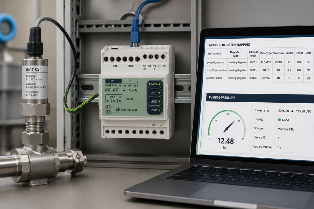
Modbus sensors can be connected comparatively easily to a PLC, data logger or edge gateway. However, successful communication does not automatically mean that the transmitted measured value is being interpreted correctly.
For example, the gateway may reliably read a register while still transmitting a completely implausible value to the cloud. Common causes include a register address shifted by one, an incorrectly selected data type, reversed word order or an unaccounted scaling factor.
Additional errors occur when only the numerical value is transferred. Without a unit, timestamp, quality status, valid range and clear device assignment, it is difficult to determine later whether a measured value is correct, outdated or the result of a communication fault.
Suitable gateways, integration services and solutions for connecting field devices to IT and cloud systems can be found in the IIoT solutions section. Modules for acquiring and outputting analogue or digital signals via Modbus are grouped together in the Modbus I/O category.
Contents
- From the sensor register to the IIoT measured value
- Distinguishing between Modbus RTU and Modbus TCP
- Documenting device addresses and communication parameters
- Correctly assigning the register type and register address
- Considering the data type, register length and sign
- Correctly configuring byte and word order
- Applying the scaling factor, offset and unit
- Mapping quality status and error values
- Defining timestamps and polling intervals
- Creating the mapping in the edge gateway
- Which information belongs in a mapping table?
- Checking the mapping using reference values
- Typical integration errors
- Practical example: Incorrect pressure and temperature values in the dashboard
- Recommended integration procedure
- Which products and solutions are suitable?
- Conclusion
- Frequently asked questions
From the sensor register to the IIoT measured value
Several processing steps take place between the physical measured value and its display on the dashboard:
- The sensor detects the physical measurand.
- The internal electronics convert the value into a digital numerical value.
- The value is stored in one or more Modbus registers.
- A Modbus client reads the registers.
- The gateway interprets the data type, order and scaling.
- The engineering value is assigned a unit and measuring-point ID.
- The gateway adds a timestamp and quality status.
- The dataset is transmitted, for example, via MQTT or HTTPS.
- A dashboard, database or analysis software processes the value further.
An error in just one of these steps can result in a value being stored that appears plausible but is technically incorrect. Errors that do not trigger a communication fault are particularly critical. A measured value scaled incorrectly by a factor of ten may be recorded for months without the system reporting a technical error.
The mapping should therefore describe more than just the data transfer. It must define the complete meaning of the measured value, from the raw register through to the target variable.
Distinguishing between Modbus RTU and Modbus TCP
Modbus RTU
Modbus RTU is typically transmitted over a serial RS-485 connection. Several devices can be operated on a shared bus. Each device requires a unique slave address.
For communication to work, the client and sensor must use the same communication parameters:
- slave address,
- baud rate,
- number of data bits,
- parity,
- number of stop bits,
- timeout and retry settings.
The bus topology, terminating resistors, shielding and reference potential must also be suitable for the RS-485 installation. Star-shaped wiring or long stubs can cause intermittent communication faults.
Modbus TCP
Modbus TCP transmits Modbus telegrams over Ethernet and TCP/IP. Instead of baud rate and parity, the IP address, subnet, port and, where applicable, the unit identifier are required.
The unit identifier may be relevant when a Modbus TCP gateway accesses downstream Modbus RTU devices. It must therefore not be ignored as a general rule.
Modbus TCP should not be forwarded directly from a production network to the public internet. A controlled edge gateway should be used for the IIoT connection, separating OT communication from the encrypted connection to IT or cloud systems.
Documenting device addresses and communication parameters
The documentation should clearly assign each Modbus device to an actual measuring point. A simple list of slave addresses is not sufficient.
Useful information includes:
- system and measuring-point designation,
- manufacturer and device type,
- serial number or asset ID,
- Modbus RTU or Modbus TCP,
- slave address or IP address,
- serial parameters or TCP port,
- firmware version,
- version of the Modbus manual used,
- position in the control cabinet or system.
If a sensor is replaced and the new device has a different firmware version, the register model may also change. The firmware and documentation version should therefore form part of the mapping approval.
Correctly assigning the register type and register address
Modbus distinguishes between four basic data areas:
| Data area | Typical function | Access |
|---|---|---|
| Coils | Binary switching values | Read and write |
| Discrete Inputs | Binary states or inputs | Read only |
| Input Registers | Measured and input values as 16-bit words | Read only |
| Holding Registers | Measured values, parameters or setpoints | Read and, in some cases, write |
A value stored in an input register cannot automatically be read using the same request as a holding register. The register type and the resulting function code must therefore be included in the mapping table.
Zero-based and one-based addressing
A common source of errors is the different representation of register addresses. A device manual may, for example, specify holding register 40021, while the gateway software expects the corresponding zero-based offset 20.
Other programs expect 40021 or 21 directly. It is therefore impossible to determine the required input format reliably from the displayed number alone.
The following should be documented for every project:
- address from the device manual,
- register type,
- zero-based protocol offset,
- value actually entered in the gateway.
A successful read request does not prove that the correct address is being used. A neighbouring register may also contain a valid numerical value.
Considering the data type, register length and sign
A single Modbus register contains one 16-bit word. However, an engineering value may consist of one or more registers.
Typical data types include:
- UINT16: unsigned integer in one register,
- INT16: signed integer in one register,
- UINT32: unsigned integer in two registers,
- INT32: signed integer in two registers,
- FLOAT32: floating-point number in two registers,
- FLOAT64: floating-point number in four registers,
- bit field: several status items within one register.
If a negative INT16 value is interpreted as UINT16, a large positive number is produced. For example, −10 may become 65526.
For values that extend over several registers, the correct start address and number of registers must also be configured. A FLOAT32 value must not be processed as two independent 16-bit values.
Correctly configuring byte and word order
For multi-part values, the gateway must know the order in which the bytes and registers are combined. Different variants are particularly common with 32-bit floating-point values.
For four bytes A, B, C and D, the following representations are possible, among others:
- ABCD,
- BADC,
- CDAB,
- DCBA.
Manufacturers and software use terms such as Big Endian, Little Endian, Byte Swap, Word Swap or Mixed Endian. These terms are not used consistently by every software package.
The safest method is to compare the result with a known reference value:
- Read the current value from the device display or the manufacturer’s software.
- Record the two raw registers in hexadecimal format.
- Test all supported byte and word orders.
- Use only the variant that produces the known value correctly.
The tested order should be documented as an explicit byte sequence and not only as a potentially ambiguous term such as “Little Endian”.
Applying the scaling factor, offset and unit
Many devices do not transmit a finished floating-point number, but rather a scaled integer. A raw value of 253 may, for example, represent 25.3 °C.
A general conversion formula is:
Engineering value = raw value × factor + offset
Examples:
| Raw value | Factor | Offset | Result |
|---|---|---|---|
| 253 | 0.1 | 0 | 25.3 °C |
| 1250 | 0.01 | 0 | 12.50 bar |
| 500 | 0.1 | −50 | 0.0% |
The unit must not be derived solely from the sensor name. Depending on its configuration, a pressure sensor may transmit bar, mbar, kPa or MPa. A temperature value may be provided in °C, K or a manufacturer-specific scaled raw format.
At least the following should be stored in the IIoT data model:
- engineering value,
- unit,
- raw value or raw registers for diagnostic purposes,
- factor and offset used,
- valid range.
A change to the unit configured in the device must not alter the meaning of the transmitted number unnoticed. Parameter changes in the sensor must therefore be reconciled with the gateway configuration.
Mapping quality status and error values
A transmitted numerical value is only useful if it is also known whether the value is valid. The quality status should not be derived solely from the numerical range.
Possible quality states include:
- Good: communication and device status are fault-free.
- Uncertain: a value is available, but it may, for example, lie outside the calibrated range.
- Bad: the sensor reports an internal fault.
- Communication Error: the device does not respond or the telegram is invalid.
- Stale: the last known value is older than the permissible update time.
- Maintenance: the device is in maintenance or simulation mode.
Many sensors have separate status registers or bit fields. A bit may, for example, indicate sensor breakage, overload, a configuration error or maintenance requirements. This information should not be discarded.
Certain raw values may also be reserved as error indicators, for example:
- maximum register value,
- minimum negative numerical value,
- NaN for floating-point values,
- manufacturer-specific substitute value.
Such values must not be written to the database as genuine process values. Their exact meaning must be taken from the relevant device manual.
Defining timestamps and polling intervals
An IIoT measured value requires a traceable time reference. Several different points in time must be distinguished:
- time of measurement in the sensor,
- time of the Modbus request by the gateway,
- time of transmission,
- time of arrival in the cloud or database.
If the sensor does not provide its own timestamp, the gateway should use the time of the successful request. The gateway clock must be synchronised reliably for this purpose.
The Modbus polling interval and transmission interval do not have to be identical. A gateway may, for example, poll every second but transmit only the average, minimum and maximum every 30 seconds.
The following should be considered when defining the intervals:
- dynamics of the measurand,
- sensor response time,
- number of devices on the bus,
- baud rate and telegram length,
- cloud and mobile data costs,
- required alarm response time,
- local buffering during connection interruptions.
Very fast polling does not improve the measured value if the sensor itself updates internally only every ten seconds.
Creating the mapping in the edge gateway
The edge gateway should not merely forward raw registers. It should map the Modbus data to a uniform, manufacturer-independent data model.
A useful dataset may contain:
{
  "asset_id": "waterplant-pump02-pressure01",
  "value": 12.48,
  "unit": "bar",
  "timestamp": "2026-08-04T07:15:30Z",
  "quality": "good",
  "source": "modbus-rtu",
  "slave_id": 7
}
The payload does not have to look exactly like this in every system. The decisive factor is that the same meaning is represented consistently throughout the system.
The gateway typically performs the following tasks:
- Modbus polling,
- combining multiple registers,
- data-type and endianness conversion,
- scaling and unit assignment,
- limit and plausibility checks,
- quality status,
- timestamping,
- local data buffering,
- transmission via MQTT, HTTPS or OPC UA.
Modbus communication and the cloud connection should be clearly separated. The gateway communicates locally with the field devices and provides only the required secured services externally.
Which information belongs in a mapping table?
A complete mapping table should contain at least the following columns:
| Field | Example |
|---|---|
| Asset ID | pump02-pressure01 |
| Device / firmware | Pressure sensor, firmware 2.4 |
| Interface | Modbus RTU |
| Slave address | 7 |
| Register type | Holding Register |
| Manual address | 40021 |
| Gateway offset | 20 |
| Number of registers | 2 |
| Data type | FLOAT32 |
| Byte/word order | CDAB |
| Factor / offset | 1 / 0 |
| Unit | bar |
| Valid range | 0 to 25 bar |
| Status register | 30005, bit 2 = sensor fault |
| Polling interval | 1 s |
| Target variable / topic | plant/pump02/pressure |
| Verification status | Verified on 4 August 2026 |
The table should also include a responsible person, version number and change history. A mapping file without version control quickly becomes unreliable following subsequent modifications.
Checking the mapping using reference values
Commissioning should not be based exclusively on successful communication. Every important measured value must be compared with a known reference state.
A useful test includes:
- Read the value from the device display or the manufacturer’s software.
- Record the raw registers using an independent Modbus test program.
- Manually check the data type and register order.
- Check the scaling and unit.
- Compare the value at the gateway.
- Check the transmitted value in the dashboard or target system.
- Simulate a sensor fault or communication failure.
- Check the quality code and alarm response.
- Check the timestamp and update interval.
Ideally, at least one low, one medium and one high measured value should be checked. Scaling and sign errors are more likely to be detected this way than with only one operating point.
Typical integration errors
| Fault pattern | Probable cause | Recommended check |
|---|---|---|
| Value is shifted by one register | Zero-based and one-based addressing have been confused | Compare the manual address, register type and gateway offset |
| Extremely large or small random number | Incorrect data type or word order | Evaluate the raw registers in hexadecimal format |
| Value is incorrect by exactly a factor of 10 or 100 | Scaling factor is missing | Check the factor and decimal places in the manual |
| Negative values appear as positive values | INT interpreted as UINT | Configure a signed data type |
| Value remains constant although the process changes | Incorrect register or outdated value | Observe the raw register during a process change |
| Dashboard continues to display a value despite sensor failure | Last value is reused without a quality status | Configure a timeout and stale status |
| Unit in the dashboard is incorrect | Device configuration and gateway mapping do not match | Compare the current sensor unit and mapping version |
| Individual devices fail intermittently | Bus load, wiring or timeout settings are unsuitable | Check the RS-485 topology and polling cycle |
Practical example: Incorrect pressure and temperature values in the dashboard
In a water-treatment system, a pressure sensor and temperature transmitter are to be connected to an edge gateway via Modbus RTU. Communication works immediately, but the values displayed in the dashboard are implausible.
The temperature transmitter provides the raw value 253 in register 30011. The gateway transfers the value without scaling and displays 253 °C. According to the device manual, however, a factor of 0.1 applies. The correct measured value is 25.3 °C.
The pressure sensor transmits a FLOAT32 value using holding registers 40021 and 40022. The gateway expects a zero-based offset as the start address, but 40021 was entered. After correcting the entry to offset 20, the correct registers are read.
The displayed pressure nevertheless remains implausible. The raw registers show that the two 16-bit words are reversed compared with the gateway’s default configuration. After activating Word Swap, a plausible value of 6.42 bar is obtained.
A status register is also integrated. Bit 2 indicates an internal sensor fault. When this bit is set, the gateway changes the quality code to “Bad” instead of continuing to transmit the last valid pressure value without identification.
A mapping table is then created for both measuring points. It contains the register address, offset, data type, order, scaling, unit, status bits, polling interval and firmware version.
After the corrections, three reference points are checked and compared with the local displays. Only then is the mapping approved for production operation.
Recommended integration procedure
- Record all sensors, measuring points and target systems.
- Obtain the current device and Modbus manuals.
- Document the firmware versions.
- Define Modbus RTU or TCP and the communication parameters.
- Assign the register type, address and gateway offset.
- Define the number of registers and data type.
- Verify the byte and word order using a reference value.
- Apply the scaling factor, offset and unit.
- Evaluate status registers, error values and valid ranges.
- Define the polling and transmission intervals.
- Define the timestamp and quality-code concept.
- Configure the mapping in the edge gateway.
- Compare the raw value, gateway value and target-system value.
- Deliberately simulate communication and sensor faults.
- Version and approve the mapping table.
Which products and solutions are suitable?
IIoT solutions
The IIoT solutions category covers the connection of sensors, actuators and control systems to edge gateways, control systems, databases and cloud platforms.
Implementation may include device selection, gateway configuration, register mapping, the data model, MQTT or HTTPS connectivity, local buffering, verification and documentation.
DMB 96500 universal AI/DI module
The DMB 96500 acquires different sensor signals such as resistance thermometers, thermocouples, current, voltage, resistance, frequency and PWM.
The measured value and configuration can be read or adjusted via Modbus RTU. The module is therefore suitable for integrating existing sensors into a Modbus-based data-acquisition system.
DMB 96200 four-channel AI module
The DMB 96200 has four galvanically isolated analogue inputs. The channels can be configured as current or voltage inputs and read via Modbus RTU.
The galvanic isolation reduces the risk of measurement errors caused by potential differences and interference voltages between the connected signal circuits.
DMB 96400 four-channel analogue I/O module
The DMB 96400 offers four independently configurable and galvanically isolated I/O channels. Depending on the channel, analogue input and output signals as well as digital functions can be provided.
This allows existing analogue measuring and control signals to be integrated into a Modbus RTU structure.
DMB 96000 Modbus RTU connection module
The DMB 96000 is used to connect Modbus RTU and the power supply to installations using the In-Rail bus system.
It supports a clearly organised installation of several Modbus I/O modules on a DIN rail and reduces the wiring effort inside the control cabinet.
Conclusion: A Modbus register is not yet a complete IIoT measured value
Stable Modbus communication is only the first step in IIoT integration. A technically usable measured value is created only when the register type, address, data type, order, scaling and unit have been assigned correctly.
Errors caused by different addressing conventions, reversed register words and unaccounted scaling factors are particularly common. These errors often do not generate a communication fault and can therefore remain undetected for a long time without a reference check.
A complete mapping also includes the timestamp, valid range, error values, device status and quality code. In the event of a sensor or communication fault, the last valid value must not continue to be processed without identification.
The most important basis is a version-controlled mapping table that clearly links the device manual, firmware, gateway configuration and target variable. The mapping should only be approved for production operation after comparison with known reference values.
Frequently asked questions about Modbus IIoT integration
Why does the gateway display incorrect values even though communication is working?
Common causes include reading the wrong register, using an unsuitable data type, applying the wrong byte or word order or failing to apply a scaling factor.
What is the difference between a register address and an offset?
A device manual may, for example, specify a reference address such as 40021, while the gateway expects the zero-based offset 20. The required entry depends on the software.
Can Modbus transmit a unit directly?
Only if the specific device provides a separate register or data model for it. In many cases, the unit must be taken from the device configuration or manual and added in the gateway.
How can I determine the correct word order?
The raw registers are compared with a known measured value. The possible byte and word orders are then tested until the correctly represented value is obtained.
What does a quality code mean?
The quality code indicates whether a measured value is valid, uncertain, faulty, outdated or unavailable due to a communication fault.
Should the raw value also be stored?
This is often useful for diagnostics and commissioning. During normal operation, storing the raw value is optional, while the engineering value, unit and quality status should always be available unambiguously.
How frequently should Modbus sensors be polled?
The interval depends on the sensor dynamics, internal update rate, bus load and required alarm response time. Polling faster than the sensor’s internal update rate does not provide any additional information.
What happens during a communication failure?
After a defined period, the gateway should mark the value as stale or faulty. The last measured value must not continue to be treated indefinitely as a current value.
Does every device require its own Modbus address?
When several Modbus RTU devices are operated within the same segment, each device requires a unique address. Duplicate addresses cause communication faults or responses that cannot be assigned unambiguously.
Why should the mapping be version-controlled?
Firmware changes, device replacement and new gateway configurations can alter registers or scaling. Version control makes it possible to trace which mapping belongs to which system version.