


Thermal gas flow sensors are frequently used to measure consumption in compressed-air and technical-gas networks. They have no moving parts, cause only a low pressure loss and can directly output the standard volumetric flow rate. During operation, however, it may occasionally become apparent that the indicated consumption gradually decreases even though machines, operating times and production volumes have remained almost unchanged.
One possible cause is contamination on the thermal sensing element. Oil mist, aerosols, condensate, dust and residues from piping alter the heat transfer between the sensor and the gas flowing past it. As a result, the factory-calibrated relationship between electrical heating power, temperature difference and mass flow is no longer correct.
However, a contaminated sensor does not necessarily always read too low. An insulating oil film often causes under-reading. Liquid droplets or temporary condensation, on the other hand, can cause increased heat dissipation, sudden changes in the measured value or strongly fluctuating readings. The effect of the error depends on the type, thickness and distribution of the deposits and on the specific sensor design.
Suitable measuring instruments can be found in the ICS category Consumption Meters for Gases and Compressed Air. Systems for monitoring moisture, oil and other contaminants are grouped under Compressed-Air Quality.
Table of Contents
- How does a thermal gas flow sensor work?
- Why does contamination often cause under-reading?
- How do oil mist and aerosols affect the measurement?
- How do moisture and condensate affect the measurement?
- Where should the sensor be installed?
- Distinguishing contamination from other causes of error
- Systematic diagnosis when the indicated value is too low
- Safely cleaning the sensing element
- Comparison measurement and plausibility check
- When is recalibration required?
- Measurement in wet compressed air
- Planning preventive maintenance
- Practical example: Consumption value decreases after a dryer problem
- Typical errors at thermal flow measuring points
- Which products and solutions are suitable?
- Conclusion
- Frequently asked questions
How does a thermal gas flow sensor work?
A thermal mass-flow sensor has at least one heated sensing element and one temperature reference. The gas flowing past removes heat from the heated element. Under defined conditions, the greater the mass flow, the stronger the cooling effect.
The electronics determine the flow rate, for example, from:
- the heating power required to maintain a temperature difference,
- the temperature difference between the heated sensor and the reference sensor,
- a factory-determined calibration characteristic,
- the stored thermal properties of the selected gas type.
The thermal method responds directly to the mass flow. From this, the sensor can calculate a standard volumetric flow rate such as Nm³/h or a volumetric flow rate referenced to other reference conditions.
However, the calibration characteristic is only valid as long as the heat transfer at the sensor corresponds to the calibrated condition. An oil film, a layer of water or a solid deposit alters precisely this heat transfer.
Why does contamination often cause under-reading?
If an insulating layer forms on the heated sensing element, less heat is transferred directly to the gas flowing past it. The sensor then detects a reduced cooling effect even though the actual mass flow may be unchanged.
The electronics interpret the reduced heat dissipation as a lower flow rate. Typical consequences include:
- gradual under-reading,
- daily or monthly consumption values that are too low,
- unusually low peak values,
- apparently improved energy efficiency without a technical cause,
- deviations compared with compressor output or production consumption.
The deposit often does not form suddenly. It builds up over weeks or months. As a result, the error is often detected only late when merely performing a plausibility check.
With other types of contamination, the indicated value may also increase or become unstable. Liquid on the sensor can dissipate considerably more heat than gas. If the liquid subsequently evaporates again, time-dependent changes in the measured value occur.
How do oil mist and aerosols affect the measurement?
Oil can occur in compressed-air systems in different forms:
- as a liquid oil film,
- as a fine aerosol,
- as a vaporous hydrocarbon,
- as a mixture of oil, water and particles.
With oil-lubricated compressors, small quantities of oil may enter the compressed-air network despite the oil separator. Causes of increased contamination include worn separator elements, unsuitable filters, excessively high compressor temperatures or exceeded maintenance intervals.
Fine aerosols can settle on the sensing element. There they form a film to which dust and particles additionally adhere. Under the influence of temperature, residues can age, resinify or form an increasingly solid layer.
Typical indications of oil contamination include:
- a shiny or sticky film on the sensor,
- brown or yellowish deposits,
- traces of oil in filters, condensate drains or piping,
- increasing pressure losses across filter elements,
- an unusual smell in the compressed air,
- simultaneous quality problems at machines or products.
Piping that appears clean does not rule out oil contamination. Very fine oil films may be barely visible to the naked eye but can already affect the sensitive heat transfer.
How do moisture and condensate affect the measurement?
Water enters the compressed-air system as water vapour. If the gas temperature falls below the current pressure dew point, liquid condensate forms.
Moisture can affect a thermal flow sensor in different ways:
- Water droplets cause strong additional cooling for a short period.
- A liquid film changes the thermal properties of the sensor surface.
- Evaporation causes time-dependent and fluctuating measured values.
- Condensate binds particles and oil into persistent deposits.
- Corrosion products from the piping can settle on the sensor.
- Water accumulations locally alter the flow profile.
A moisture problem is often indicated by unstable or sudden changes in the measured values. The deviations may be particularly pronounced after the compressor starts, during load changes or after the piping cools down.
A low relative-humidity value after expansion to atmospheric pressure does not prove that there is no risk of condensation inside the pressurised line. The pressure dew point under the actual operating conditions is decisive.
Where should the sensor be installed?
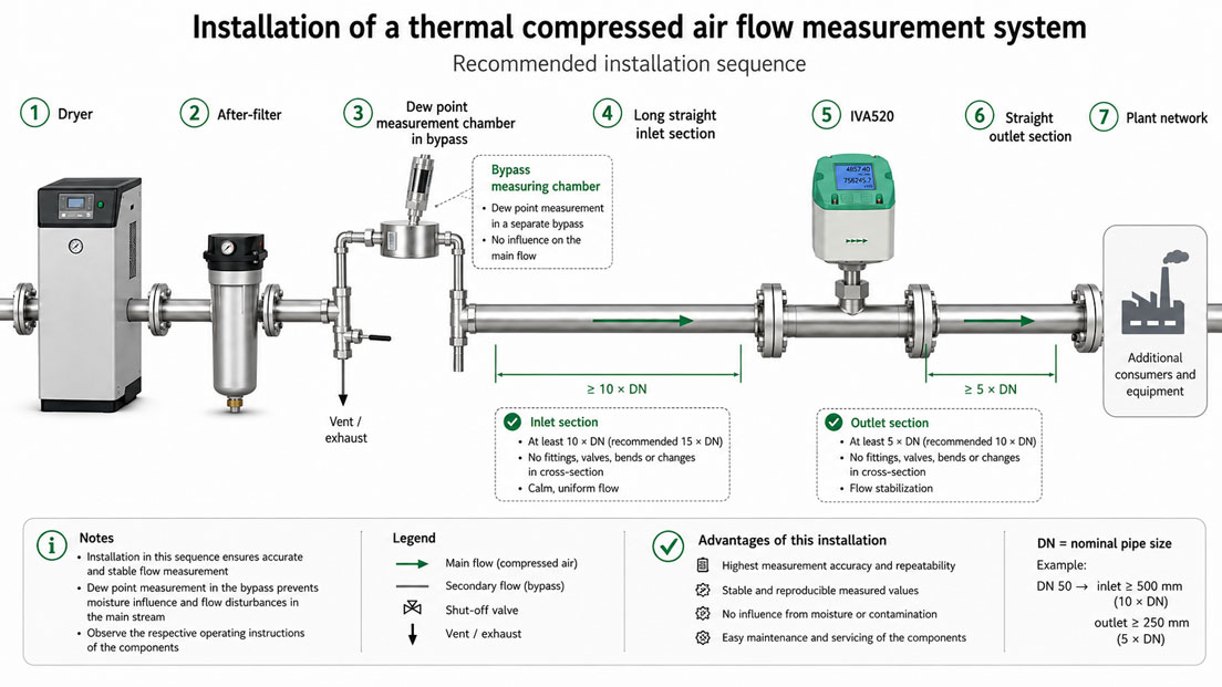
For long-term stable thermal consumption measurement, the sensor should preferably be installed in treated, non-condensing compressed air. A typical arrangement is:
Compressor → aftercooler → water separator → filter → dryer → after-filter → thermal flow sensor
The exact position depends on the measuring task. A main meter installed after complete air treatment records the compressed air supplied to the dry plant network. A machine meter is frequently installed downstream of the local maintenance or filter unit.
The following points in particular must be considered when planning the installation:
- guaranteed pressure dew point at the installation location,
- residual oil and particle loading,
- possible dryer failures or bypass operation,
- flow direction and complete filling of the pipe with gas,
- installation position according to the operating instructions,
- sufficient upstream and downstream straight pipe sections,
- distance from valves, bends, reducers and branches,
- permissible pressure and temperature range,
- accessibility for removal, cleaning and calibration.
In horizontal piping, an installation position in which condensate can permanently collect on the sensing element should be avoided. However, the approved installation position of the specific instrument is always decisive.
Distinguishing contamination from other causes of error
An indicated value that is too low is not automatically caused by contamination. Other possible errors should be checked before removing the sensor.
Incorrect gas type
Thermal sensors use the thermal properties of the stored gas type. If nitrogen is selected instead of air, for example, or an incorrect gas composition is entered, a systematic measurement error can occur.
Incorrect reference conditions
Standard volumetric flow rates can be referenced to different reference temperatures and reference pressures. If two instruments using different conditions are compared, their values may appear different even though both are functioning correctly.
Incorrect internal pipe diameter
With insertion sensors, the volumetric flow rate is calculated from the local flow velocity and the stored pipe cross-section. Even small errors in the internal diameter have a squared effect on the area.
Incorrect insertion depth or alignment
The sensing element must be located in the intended position and correctly aligned with the flow direction. A rotated probe or incorrect insertion depth measures a non-representative velocity.
Insufficient upstream straight run
Bends, valves, T-pieces, filters and reducers can generate an asymmetric or rotating flow profile. The local measured value then no longer corresponds to the mean velocity inside the pipe.
Low-flow cut-off
If the low-flow cut-off is set too high, small consumption rates and leaks are not detected. This can result in daily consumption values that are considerably too low, particularly outside production hours.
Signal-processing errors
Incorrect scaling of the 4–20 mA signal, an incorrect pulse factor or different units between the sensor, data logger and control system can also cause under-reading.
Systematic diagnosis when the indicated value is too low
- Check the trend: Determine whether the deviation occurred suddenly or developed gradually.
- Compare the local indication: Compare the sensor display, analogue signal, bus value and totaliser reading.
- Record the parameters: Document the gas type, reference conditions, pipe diameter, unit, analogue scaling and pulse value.
- Record the process conditions: Record the pressure, temperature, pressure dew point, compressor load and operating condition.
- Check the air-treatment system: Check the filter condition, differential pressure, condensate drains and dryer operation.
- Inspect the measuring point: Check the installation position, insertion depth, flow direction and flow-conditioning sections.
- Check standstill consumption: Observe whether known leakage flows are still recorded plausibly.
- Perform a comparison measurement: Use a suitable reference sensor or an independent mass balance.
- Remove the sensor in a controlled manner: Only after depressurisation and in accordance with the operating instructions.
- Inspect the sensing element: Check for an oil film, droplets, dust, corrosion and solid deposits.
- Perform cleaning or servicing: Exclusively in accordance with the manufacturer’s instructions.
- Document the as-found and as-left values: Compare the condition before and after cleaning or calibration.
Simply resetting the zero point is not a suitable solution for a contaminated sensor. This may conceal part of the deviation, but the characteristic curve across the entire measuring range remains altered.
Safely cleaning the sensing element
The sensing element of a thermal flow meter is a sensitive precision component. It must not be treated like an ordinary piping component.
The manufacturer’s instructions for the specific sensor must be observed before any cleaning operation. The following general principles apply:
- Completely depressurise the piping and secure it against being repressurised.
- Do not hold or support the sensor by the sensitive measuring head.
- Do not use wire brushes, abrasives or sharp-edged tools.
- Do not scrape off deposits using screwdrivers or needles.
- Do not use unsuitable solvents or aggressive cleaning agents.
- Do not blow off the sensor using unfiltered workshop compressed air.
- Protect the electronics and electrical connections from liquids.
- Allow the sensor to dry completely without leaving residues after cleaning.
- Check the seals and installation components before reinstallation.
For thin, soluble contamination, a cleaning procedure approved by the manufacturer may be sufficient. Resinified deposits, corrosion, damaged sensor surfaces or unknown media, however, require professional inspection by the manufacturer.
If the mechanical or thermal structure of the sensing element is damaged, cleaning cannot restore the original calibration.
Comparison measurement and plausibility check
A comparison measurement is only meaningful if both measuring instruments detect the same gas quantity and the same operating conditions.
The following points must be checked:
- the same measuring period,
- the same gas type,
- the same reference conditions,
- comparable units,
- no branch or leak between the measuring points,
- sufficiently stable flow,
- suitable measuring ranges of both instruments,
- valid calibration status of the reference instrument.
A balance can also provide useful indications. Over a sufficiently long period, the total consumption measured by the main meter should approximately correspond to the sum of the sub-meters plus known leaks and losses.
The theoretical delivery rate of a compressor is only of limited suitability as a reference. Intake conditions, control status, wear, pressure, temperature and actual operating time influence the real delivery rate.
When is recalibration required?
Cleaning does not automatically prove that the sensor once again measures within its specification. Recalibration is particularly advisable:
- for consumption values used for billing,
- after visible heavy contamination,
- after contact with liquid oil or condensate,
- after mechanical damage,
- if a deviation is detected during a comparison measurement,
- after many years of operation without metrological verification,
- if the sensor was operated outside its temperature or pressure limits.
Calibration should cover several points within the actually used measuring range wherever possible. A zero point or a single intermediate flow value is not sufficient to assess the complete characteristic curve.
For traceable maintenance, the values before adjustment or cleaning must be documented as as-found data and the values after the measure as as-left data.
Measurement in wet compressed air
If the flow is to be measured directly downstream of the compressor or upstream of the dryer, high moisture levels and temporary liquid condensate must be expected. A conventional thermal consumption sensor for dry compressed air is often not the best choice for this installation location.
Robust differential-pressure methods may be more suitable for such applications. They determine the flow, for example, from the dynamic or differential pressure and additionally take pressure and temperature into account when calculating density.
Even with a differential-pressure sensor designed for wet compressed air, the condensate drain, installation position, pressure-tapping openings and maintenance accessibility must be planned. “Suitable for wet compressed air” does not mean that arbitrary quantities of liquid can pass through the measuring point without affecting it.
The measuring principle should therefore be selected according to the actual installation location:
| Installation location | Typical condition | Possible measuring solution |
|---|---|---|
| Directly downstream of the compressor | Hot, humid, with possible condensate and oil contamination | Differential-pressure method designed for wet compressed air |
| Downstream of the dryer and filter | Dry, treated compressed air | Thermal mass-flow sensor |
| Main distribution system | Largely dry compressed air, large piping | Thermal insertion probe or inline measuring section |
| Machine connection | Smaller piping, defined consumer | Compact inline consumption meter |
Planning preventive maintenance
A thermal flow sensor requires little maintenance, but it is not fundamentally maintenance-free. The maintenance interval must be adapted to the actual compressed-air quality and the importance of the measured value.
A suitable maintenance concept includes:
- regular plausibility checks of consumption trends,
- monitoring of the pressure dew point,
- checking the differential pressure across the filters,
- functional testing of the condensate drains,
- monitoring of the residual oil content in critical applications,
- visual inspection of the sensor during scheduled shutdowns,
- periodic comparison measurements,
- a defined recalibration interval,
- documentation of cleaning, replacement and parameter changes.
An automatic alarm for an elevated pressure dew point can prevent a dryer problem from remaining unnoticed for a prolonged period and contaminating several sensors in the compressed-air network.
Practical example: Consumption value decreases after a dryer problem
A thermal inline consumption meter is installed downstream of a refrigeration dryer and a filter. For several months, the daily consumption of a production line was approximately 8,000 Nm³. The indicated value then gradually falls to approximately 7,000 Nm³ even though the production volume and machine operating times remain unchanged.
The following observations are made during the inspection:
- The local indication and the Modbus value match.
- The gas type, pipe diameter and reference conditions have not been changed.
- A mobile comparison measurement indicates approximately 13% more flow.
- A dryer alarm is visible several weeks earlier in the trend of the dew-point sensor.
- The condensate drain on the pre-filter was temporarily blocked.
- A thin oil-water film is present on the removed sensing element.
The sensor is cleaned in accordance with the approved service instructions and subsequently checked at several flow points. The deviation from the reference measurement is then once again within the defined tolerance.
In addition, the condensate drain is replaced, the filter elements are changed and an alarm for an excessively high pressure dew point is configured. The case shows that cleaning the flow sensor alone is not sufficient. The cause of the contamination must also be eliminated.
Typical errors at thermal flow measuring points
| Error | Possible consequence | Suitable corrective action |
|---|---|---|
| Thermal sensor installed directly downstream of the compressor | Contact with wet, hot and oil-contaminated compressed air | Select a suitable measuring principle for wet compressed air |
| Dryer malfunction not detected | Condensate reaches the sensor and consumers | Continuously monitor the pressure dew point |
| Oil separator or filter overdue for maintenance | Oil film and particle deposits on the sensing element | Maintain the air-treatment system and check the residual oil loading |
| Sensor checked only visually | Thin, barely visible films remain undetected | Perform a comparison measurement and calibration check |
| Incorrect gas type selected | Systematic deviation across the measuring range | Check and document the gas parameters |
| Different standard conditions compared | Apparent deviation despite correctly functioning instruments | Align the reference pressure and reference temperature |
| Insertion sensor incorrectly aligned | Non-representative flow velocity | Check the insertion depth and flow direction |
| Low-flow cut-off set too high | Leaks and low consumption rates are missing from the totaliser reading | Set the threshold to suit the application |
| Sensing element cleaned mechanically | Damage and permanent characteristic deviation | Use only an approved cleaning method |
| No verification performed after cleaning | Unknown remaining measurement deviation | Provide a multipoint check or recalibration |
Which products and solutions are suitable?
IVA520 thermal inline consumption meter
The IVA520 measures the flow and consumption of compressed air and non-corrosive gases using the thermal mass-flow principle. The pipe diameter and sensor position are structurally defined by the integrated measuring section.
The sensor head can be removed for cleaning or recalibration while the measuring section remains installed in the piping and is sealed using a suitable blanking cap. This facilitates regular metrological checks.
IVA500 thermal insertion sensor
The IVA500 is suitable for consumption measurement in larger compressed-air and gas lines. With insertion sensors, the internal pipe diameter, insertion depth, alignment and flow profile must be considered particularly carefully.
IVA550 and IVA570
The IVA550 is a robust thermal mass-flow sensor for compressed air and various technical gases. The IVA570 combines the thermal measuring principle with an integrated measuring section for precise and reproducible installation conditions.
The permissible gas quality and possible deposits on the sensing element must also be considered with robust industrial versions.
IFA510 and IFA515 dew-point sensors
The IFA510 and IFA515 monitor the pressure dew point in compressed-air and dryer systems. Continuous dew-point measurement makes it possible to detect dryer problems before condensate enters the piping network and reaches sensitive flow sensors.
OIL CHECK 500
The OIL CHECK 500 is used to monitor the vaporous residual oil content in treated compressed air and nitrogen. It is typically installed downstream of filtration and drying and supports monitoring of the required compressed-air quality.
The instrument does not automatically measure all liquid oil aerosols or types of condensate at any arbitrary installation location. The sampling system, moisture conditions and operating limits must suit the respective application.
IVD500 and IVD520 for wet compressed air
The IVD500 and the IVD520 operate according to a differential-pressure method and are intended, among other applications, for wet compressed air. They therefore provide a possible alternative when flow must be measured upstream of the dryer or under humid conditions.
CMM 500 Compressor Master Meter
The CMM 500 Compressor Master Meter was developed for the precise measurement of compressor delivery rates and for reference measurements in compressed-air systems. It can be used for the independent assessment of main meters, compressor performance and consumption balances.
ICS Schneider Messtechnik provides support in selecting the appropriate measuring principle, positioning it within the compressed-air network, monitoring the pressure dew point and residual oil, and performing comparison measurements, cleaning, recalibration and preventive maintenance.
Conclusion
A thermal gas flow sensor can gradually indicate incorrect consumption values because of oil, water and solid deposits. An insulating film frequently causes under-reading, while condensate droplets can also cause increased or unstable measured values.
Configuration, installation and signal errors must be ruled out before cleaning. The gas type, reference conditions, pipe diameter, insertion depth, flow profile and low-flow cut-off can cause similar deviations.
The best protection is a suitable installation position downstream of the dryer and filtration system, together with continuous monitoring of the compressed-air quality. The pressure dew point, filter condition, condensate drains and, where applicable, residual oil content provide early indications of problems.
The sensitive sensing element may only be cleaned in accordance with the manufacturer’s instructions. Mechanical treatment can permanently damage the surface. After heavy contamination or for measurements used for billing, a multipoint check or recalibration is required.
For wet compressed air directly downstream of the compressor, it should be checked whether a differential-pressure method designed for this purpose is more suitable than a thermal mass-flow sensor.
Frequently asked questions about contaminated thermal flow sensors
Does a contaminated thermal flow sensor always read too low?
No. An insulating oil or dirt film frequently causes under-reading. Liquid water or condensate can, however, increase the cooling effect and thereby cause elevated, fluctuating or sudden changes in the measured values.
Can oil mist damage a thermal sensor?
Oil mist can settle on the sensing element and alter its characteristic curve. Resinified residues or deposits formed together with particles may be difficult to remove. Permanent damage can occur if an unsuitable cleaning method is used.
How can condensate on the sensor be detected?
Typical indications include strongly fluctuating values, sudden changes in the measured value following load or temperature changes, visible droplets and simultaneously unusual pressure-dew-point or condensate-drain values.
Can the sensor be blown clean using compressed air?
Only if this is explicitly permitted by the manufacturer and a suitable clean medium is used. Unfiltered workshop compressed air can contain oil, water and particles and may additionally contaminate or mechanically damage the sensor.
Can the sensor be cleaned using alcohol?
This depends on the sensor type and the materials used. Only cleaning agents and procedures approved by the manufacturer may be used.
Is cleaning without recalibration sufficient?
With light contamination, the original condition may possibly be restored. However, this is not proven without a comparison check. The sensor should be recalibrated after heavy contamination or when important consumption values are involved.
Why do two compressed-air meters disagree even though both sensors are clean?
Possible causes include different reference conditions, gas types, measuring ranges, installation positions, pipe diameters, signal scaling or branches between the measuring points.
Can a thermal sensor be installed upstream of the dryer?
Only if the specific instrument is explicitly designed for the moisture, temperature and contamination conditions that occur there. For wet compressed air, a differential-pressure method specifically intended for this purpose is often more suitable.
How often should a thermal flow sensor be cleaned?
There is no universally applicable fixed interval. It depends on the compressed-air quality, installation location, operating time and measuring task. Trend monitoring, dew-point monitoring and regular comparison measurements enable condition-based maintenance.
Why does the sensor no longer indicate any leakage at night?
In addition to contamination, an excessively high low-flow cut-off may be the cause. Small volumetric flow rates are then set to zero and are not added to the consumption totaliser.