


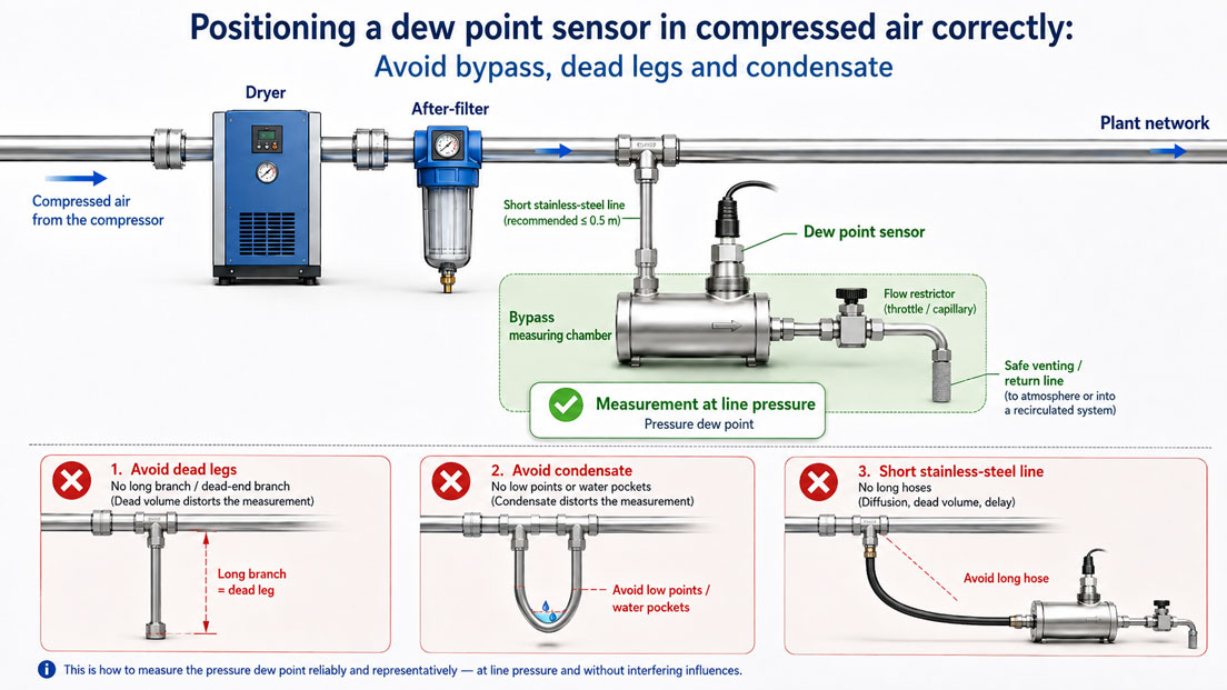
A dew point sensor can only provide reliable values if the gas at the sensing element actually represents the condition of the system being monitored. A technically high-quality probe alone is therefore not sufficient. The measuring location, pipe routing, sample flow, pressure, materials and possible condensate formation have an equally significant influence on the result.
Sensors installed in long branch lines, directly downstream of closed valves or in measuring chambers without sufficient gas flow are particularly problematic. In these locations, the sensor often does not measure the current compressed air from the main line, but rather a stagnant gas volume that has been altered by diffusion, small leaks and moisture released from the pipe walls.
Pressure reduction upstream of the sensor can also lead to misinterpretation. If the dew point is measured after expansion to atmospheric pressure, this value no longer directly corresponds to the pressure dew point inside the compressed-air line. For dryer monitoring, it must therefore be clearly defined at which pressure and at which point the measurement is to be performed.
Suitable stationary sensors can be found in the ICS category Humidity Sensors and Dew Point Sensors. Mobile measuring systems and instruments for service and verification measurements are grouped under Humidity Measuring Instruments and Dew Point Measurement.
Table of Contents
- What does a dew point sensor measure in compressed air?
- Which system condition is to be monitored?
- Should the measuring point be installed upstream or downstream of the dryer?
- Comparing direct installation and bypass measurement
- Correct technical design of a bypass measuring chamber
- Distinguishing between pressure dew point and atmospheric dew point
- Why do dead volumes cause incorrect measured values?
- Correctly setting the sample flow and measuring chamber
- Selecting the sample-line length and pipe material
- Avoiding condensate at the sensor
- Considering oil, particles and other contaminants
- Assessing response and stabilisation times
- Defining alarm limits for dryer monitoring
- Systematically commissioning the measuring point
- Planning maintenance and recalibration
- Practical example: Monitoring an adsorption dryer
- Typical errors at dew point measuring points
- Which products and solutions are suitable?
- Conclusion
- Frequently asked questions
What does a dew point sensor measure in compressed air?
The dew point is the temperature at which the water vapour contained in the gas begins to condense under the respective pressure conditions. The lower the dew point, the lower the water content of the compressed air.
In compressed-air systems, the pressure dew point is frequently stated in °Ctd. It refers to the actual line pressure at the measuring point. The pressure dew point must not be confused with the ambient temperature or relative humidity.
A dew point sensor measures the moisture directly at the sensing element. The indicated value is therefore influenced not only by the dryer, but also by:
- the pressure at the sensor,
- the temperature of the measuring chamber and sample line,
- the current gas flow,
- the length and material of the sample line,
- leaks and ambient air diffusing into the system,
- moisture released by pipe walls and seals,
- condensate, oil and particles at the sensing element,
- the sensor’s previous exposure to moisture.
The measuring point must therefore be considered as a complete system comprising the sampling point, valve, line, measuring chamber, flow restriction and sensor.
Which system condition is to be monitored?
Before defining the installation location, it is necessary to establish which condition the measurement is intended to represent.
Monitoring dryer performance
If the function of a dryer is to be assessed, the measuring point is installed downstream of the dryer or downstream of the subsequent particle filter. No wetter compressed air from a bypass or another line may be mixed in between the dryer outlet and the measuring point.
Monitoring compressed-air quality in the plant network
To monitor the entire network, the measuring point is installed at a representative location in the main distribution system. In addition to the dryer, this also detects possible moisture ingress from piping, receivers and distribution manifolds.
Checking quality at the consumer
For particularly sensitive applications, an additional measurement directly upstream of the consumer may be required. Long lines, outdoor sections, pressure vessels or lines that remain stagnant temporarily can alter the compressed-air quality between the central treatment system and the machine.
Performing service and comparison measurements
A defined test connection with a shut-off valve and measuring coupling should be provided for temporary verification measurements. The mobile instrument should not be connected to an arbitrary vent connection, but to a representative point with sufficient gas exchange.
Should the measuring point be installed upstream or downstream of the dryer?
A dew point measurement upstream of the dryer indicates the moisture loading of the incoming compressed air. It can be useful for process analysis or assessing the dryer load, but it does not replace monitoring of the compressed air that has actually been dried.
For monitoring dryer performance, the sensor is normally installed downstream of the dryer. A typical arrangement is:
Compressor → aftercooler → water separator → pre-filter → dryer → after-filter → dew point measuring point → plant network
The exact sequence depends on the dryer design and air-treatment concept. With adsorption dryers, an after-filter may be required to retain desiccant abrasion. With refrigeration dryers, the water separation and condensate drainage must function correctly.
The measuring point should not be located directly in a highly turbulent area downstream of a fast-switching valve, vent or condensate drain. Although a pure moisture measurement does not require a long upstream straight run as used for flow measurement, the sample must reach the measuring chamber continuously and representatively.
Comparing direct installation and bypass measurement
| Configuration | Advantages | Points to consider |
|---|---|---|
| Direct installation in the main line | Measurement directly at process pressure; no additional sample flow required | The sensor is more exposed to dirt, oil and condensate; removal may require depressurisation |
| Measuring chamber with continuous venting | Defined gas exchange, fast response and easier sensor removal | Continuous low compressed-air consumption; exhaust air must be discharged safely |
| Closed bypass with return line | No permanent loss of process gas; suitable for expensive or problematic gases | A pressure difference between the sampling and return points is required to generate flow |
| Branch line without continuous flow | Simple mechanical design | High risk of non-representative measurement due to stagnant gas and diffusion |
For many compressed-air applications, a measuring chamber in a bypass is the most practical solution. The sensor is not completely separated from the process. It is located in a measuring chamber with controlled flow, in which approximately the same pressure is present as in the main line.
Correct technical design of a bypass measuring chamber
A typical measuring point for determining the pressure dew point consists of the following components in the direction of flow:
Main line → sampling point → shut-off valve → short sample line → measuring chamber with dew point sensor → flow restriction → safe vent
For pressure dew point measurement, the flow restriction is positioned downstream of the sensor. This keeps the measuring chamber at approximately the line pressure. If the compressed air were expanded upstream of the measuring chamber, the sensor would measure the dew point at the reduced pressure.
The following principles apply to a technically correct bypass measuring point:
- Provide the sampling point at a representative location in the main line.
- Keep the sample line as short as possible and minimise its dead volume.
- Install the shut-off valve directly at the process sampling point.
- Mount the sensor in a measuring chamber intended for this purpose.
- Position the flow restriction or capillary downstream of the measuring chamber.
- Do not discharge the exhaust air against an unexpected back pressure.
- Use a closed bypass for hazardous or expensive gases.
- Ensure that all connections are gas-tight.
- Position the measuring chamber so that it is readily accessible for maintenance and calibration.
If the sample is returned to the main line, the return point must have a lower pressure than the sampling point. Without a pressure difference, no reliable bypass flow will be generated.
Distinguishing between pressure dew point and atmospheric dew point
The dew point depends on pressure. When compressed air is expanded, the water-vapour partial pressure decreases. The expanded sample can therefore have a significantly lower atmospheric dew point than the pressure dew point inside the line.
For monitoring a compressed-air dryer, the pressure dew point at line pressure is generally required. In this case, the sensor must be positioned upstream of the pressure reduction.
Measurement downstream of a pressure regulator may be useful if the dew point under the conditions of the expanded air at the consumer is specifically to be assessed. However, this measured value must not be compared with a limit defined at line pressure without conversion.
The documentation should therefore include at least:
- the measured dew point or frost point,
- the pressure in the measuring chamber,
- the gas temperature,
- the gas type,
- the measuring location and system condition,
- where applicable, the atmospheric dew point calculated from these values.
A dew point value without specification of the measuring pressure provides only limited information in compressed-air applications.
Why do dead volumes cause incorrect measured values?
A dead volume is a section of piping or a cavity in which there is no sufficient continuous gas exchange. Typical examples include:
- long closed-end branch lines,
- measuring connections downstream of permanently closed valves,
- large measuring chambers without a defined sample flow,
- unused T-pieces or manifolds,
- hoses with an unnecessarily large internal diameter,
- measuring lines that are opened only briefly.
The moisture content inside a dead volume can be altered by several processes:
- Moisture diffuses through plastic hoses and seals.
- Ambient air enters through small leaks.
- Water is absorbed or released by the internal surfaces of the line.
- Oil and dirt deposits retain moisture.
- A previous humid system condition remains in the dead volume for a long time.
The sensor may then indicate a stable value even though it does not correspond to the current condition of the main line. A stable indication is therefore not automatically proof of a representative measurement.
Correctly setting the sample flow and measuring chamber
The measuring chamber requires a small but continuous gas flow. This ensures that the gas volume is regularly exchanged and that the sensor can respond to changes in the main line.
For many standard measuring chambers, the intended sample flow is approximately 1 l/min. High-pressure or special measuring chambers may require different values. The manufacturer’s specifications are always decisive.
An insufficient flow causes:
- long response times,
- a greater influence from dead volume and diffusion,
- delayed detection of dryer malfunctions,
- a greater influence from small leaks.
An unnecessarily high flow, on the other hand, results in:
- increased compressed-air consumption,
- possible cooling and an additional risk of condensation,
- greater loading of the measuring chamber and exhaust line,
- unnecessary noise generation.
The flow restriction must not be adjusted by feel if the measuring chamber uses a defined nozzle or capillary. With adjustable solutions, it is advisable to check the flow using a suitable flow meter.
Selecting the sample-line length and pipe material
With very dry compressed air, unsuitable sample lines can significantly influence the measurement result. Hygroscopic or moisture-permeable materials absorb water vapour and release it again later.
For consistently low dew points, stainless-steel tubing is generally particularly suitable. It has low moisture absorption, low gas permeability and can be connected gas-tight.
The following recommendations apply when planning the sample line:
- Keep the sample line as short as possible.
- Do not select an unnecessarily large internal diameter.
- Prefer stainless steel for very low dew points.
- Only use flexible plastic or rubber hoses if their suitability has been confirmed.
- Avoid unnecessary fittings, adapters and dead volumes.
- Check all connections for leaks.
- Flush the line sufficiently before measurement.
- Do not use lubricants or sealants that release or introduce moisture.
A long plastic line can distort the measured value even if it appears to be completely leak-tight mechanically. Water vapour can diffuse through the material or desorb from the inner wall of the hose.
Avoiding condensate at the sensor
A dew point sensor is intended to measure water vapour in a gas. Liquid water on the sensing element causes temporary saturation and can result in a long recovery time.
Condensate may form if:
- the gas temperature falls below the current pressure dew point,
- a humid line cools down after a shutdown,
- a dryer or condensate drain fails,
- the sample line passes through a cold outdoor area,
- pressure expansion or flow causes strong local cooling,
- liquid water from the main line enters the measuring chamber.
To prevent condensate, the sample line should be routed without low points or liquid traps. The sampling point must not be located where liquid normally collects during operation.
Repeated exposure to liquid water should also be avoided with a sensor described as resistant to condensation. Resistance to condensation does not mean that condensate has no influence on response time, measured value or contamination.
Considering oil, particles and other contaminants
Oil mist, aerosols, dust and desiccant abrasion can contaminate the protective cap and sensing element. Deposits increase the response time and can influence the sensor dynamics or calibration.
A dew point measuring point should therefore be installed downstream of the intended filtration. However, installing an arbitrary additional filter directly upstream of the measuring chamber is not automatically beneficial. Filter materials can absorb moisture and delay the response.
The following points in particular should be checked:
- condition of the pre-filters and after-filters,
- function of the condensate drains,
- oil carry-over from the compressor,
- abrasion from an adsorption dryer,
- cleanliness of the measuring chamber and sample line,
- condition of the sensor’s stainless-steel sintered cap.
If contamination is detected, the sensitive sensing element may only be cleaned in accordance with the manufacturer’s instructions. Mechanical aids, unsuitable solvents or unfiltered workshop compressed air can damage or additionally contaminate the sensor.
Assessing response and stabilisation times
The time required to obtain a stable measured value does not depend solely on the sensor. The measuring chamber, line volume, material, sample flow and previous moisture loading also play a role.
Particularly long stabilisation times occur with:
- long or high-volume sample lines,
- plastic and rubber hoses,
- very low sample flows,
- previous condensation on the sensor,
- oil and dirt deposits,
- changes from very humid to very dry compressed air,
- leaks that allow ambient air to enter.
A measurement should not be ended after an arbitrary waiting period. The decisive factor is that the trend has stabilised and that the change over a reasonable period remains only within the expected measured-value fluctuation.
For mobile measurements, the sample line should be flushed sufficiently before recording begins. A sensor that was previously stored in ambient air may require considerably more time in very dry gas than during a verification measurement in a similar dew point range.
Defining alarm limits for dryer monitoring
An alarm limit should be derived from the required compressed-air quality and not solely from the dryer’s nominal dew point.
The following factors must be considered when defining the limit:
- required maximum pressure dew point at the consumer,
- guaranteed outlet dew point of the dryer,
- measurement uncertainty of the sensor,
- time delay of the measuring point,
- possible fluctuations during dryer switching and regeneration,
- moisture ingress between the dryer and consumer,
- response time of the operational corrective measures.
A two-stage monitoring system is useful in many installations:
- Pre-alarm: provides early warning of deterioration and enables a maintenance response.
- Main alarm: indicates that the permissible operating condition has been exceeded and can initiate switching or shutdown.
The alarm limit should not be set exactly at the permissible quality limit. Measurement uncertainty and response time require an appropriate safety margin.
Short-term measured-value peaks must not be filtered out without evaluation. They may indicate dryer switching, condensate breakthrough or disrupted regeneration. At the same time, a suitable delay must prevent every brief normal fluctuation from triggering a false alarm.
Systematically commissioning the measuring point
- Check the measuring objective: Clearly define whether the dryer outlet, plant network or consumer is the condition to be monitored.
- Select the sensor: Choose a measuring range suitable for the expected pressure dew point.
- Define the measuring pressure: Decide whether the pressure dew point or atmospheric dew point is required.
- Check the sampling point: Exclude dead legs, condensate accumulation and external feeds.
- Install the measuring chamber: Install the sensor, seals and threads in accordance with the manufacturer’s instructions.
- Position the flow restriction: For pressure dew point measurement, install it downstream of the sensor.
- Check the sample line: Verify its length, material, cleanliness and leak tightness.
- Pressurise the measuring point slowly: Build up the pressure in a controlled manner and observe the permissible sensor pressure.
- Set the sample flow: Follow the manufacturer’s specification for the measuring chamber.
- Flush the line: Completely displace old or humid gas.
- Observe the trend: Wait for a stable measured value.
- Check the signal path: Compare the local indication, 4–20 mA signal, Modbus value and control system.
- Check the alarm limits: Document the limit values and delay times.
- Document the initial condition: Record the pressure, dew point, temperature and system load.
Planning maintenance and recalibration
Even a long-term stable dew point sensor should be checked regularly. The interval depends on the measuring range, compressed-air quality, safety relevance and importance of the measured value.
A maintenance concept may include:
- regular plausibility checks of the dew point trend,
- checking the sample flow,
- checking valves and fittings for leaks,
- inspecting the measuring chamber and sintered cap,
- checking for oil and condensate residues,
- performing a comparison measurement using a mobile reference instrument,
- periodic factory or laboratory calibration,
- documenting the as-found and as-left values,
- checking the alarm function in the control system.
A suddenly and significantly lower dew point does not automatically indicate an improvement in dryer performance. A leak, changed pressure conditions or an incorrect conversion can also cause apparently better values.
Practical example: Monitoring an adsorption dryer
An adsorption dryer is to be monitored in a production plant. The line pressure is approximately 7 bar. The required pressure dew point at the outlet is well below freezing point.
The measuring point is installed downstream of the dryer and after-filter. A short stainless-steel branch leads from the main line through a shut-off valve to a measuring chamber. Downstream of the chamber, a capillary restricts the exhaust flow.
The arrangement is:
Dryer → after-filter → sampling point → shut-off valve → stainless-steel line → measuring chamber with dew point sensor → capillary → safe vent
Because the restriction is located downstream of the sensor, the pressure in the measuring chamber is approximately the same as in the main line. The sensor therefore measures the pressure dew point rather than the dew point of the already expanded compressed air.
During commissioning, it becomes apparent that the measured value decreases only very slowly. The cause is identified as a plastic hose several metres long between the sampling point and the measuring chamber. The hose is replaced with a short stainless-steel line.
After the modification, the sensor reaches a stable value considerably faster. A pre-alarm limit is also configured to provide early warning of a gradual deterioration in dryer performance.
The example shows that a slow or excessively high dew point does not necessarily indicate a defective dryer or sensor. The sample line and measuring chamber may also be responsible.
Typical errors at dew point measuring points
| Error | Possible consequence | Suitable corrective action |
|---|---|---|
| Sensor installed upstream of the dryer | Inlet moisture is monitored instead of the dryer result | Define the measuring objective and provide an outlet measuring point |
| Sensor installed in a closed branch line | Stagnant, non-representative gas is measured | Generate a continuous bypass flow through the measuring chamber |
| Pressure regulator installed upstream of the sensor | Atmospheric or reduced-pressure dew point is measured instead of the pressure dew point | For pressure dew point measurement, position the restriction downstream of the sensor |
| Sample line too long | Long response time and moisture release from the line wall | Use a short line with a low dead volume |
| Unsuitable plastic hose | Moisture diffusion and distorted low dew points | Prefer stainless steel for dry compressed air |
| Insufficient flow through the measuring chamber | Delayed or non-representative measurement | Check the intended sample flow |
| Sensor installed at a condensate collection point | Condensation and a long recovery time | Design the measuring point to remain dry and free from liquid traps |
| Leaking fitting | Humid ambient air influences the measured value | Check the entire sample path for leaks |
| Sensor used immediately after humid storage | Very long stabilisation time | Flush the sensor and measuring line sufficiently |
| Fixed alarm value without considering measurement uncertainty | False alarms or delayed response | Define a pre-alarm, main alarm and time delay |
| Oil or particle loading ignored | Slow response and possible measurement deviation | Regularly check the air-treatment system and sensor condition |
| Dew point documented without measuring pressure | Measured values cannot be compared unambiguously | Document the pressure and reference conditions as well |
Which products and solutions are suitable?
IFA510 and IFA515 for adsorption dryers
The IFA510 and IFA515 dew point sensors for adsorption dryers are intended for residual-moisture measurement in very dry compressed air and gases. They are suitable for continuous dryer monitoring and, depending on the configuration, provide analogue and digital measuring signals.
Installation in a suitable measuring chamber enables a defined gas flow, a short equilibration time and easier removal for servicing and calibration.
IFA510 and IFA515 for refrigeration dryers
The IFA510 and IFA515 dew point sensors for refrigeration dryers are available for the typical dew point range of refrigeration dryers.
The choice between the versions for refrigeration and adsorption dryers should be based on the actually expected measuring range. An unnecessarily large or unsuitable range can reduce the resolution and impair assessment of the measuring point.
IFA515 Ex for hazardous areas
The IFA515 Ex is intended for dew point and residual-moisture measurements in hazardous areas. The intrinsically safe configuration must be operated with the approved power-supply and isolating components.
IFA550 for robust outdoor and industrial applications
The IFA550 has a robust industrial enclosure and is suitable for dew point measuring points under demanding ambient conditions.
Even with a robust enclosure, representative gas sampling, a suitable measuring chamber and avoidance of condensate remain essential.
IDS52 sets for dryer monitoring
The IDS52 set for refrigeration dryers and the IDS52 set for adsorption dryers combine a dew point sensor, display or alarm function and suitable accessories into a monitoring solution.
IDP400 mobile
The IDP400 mobile combines mobile dew point and pressure measurement in a robust system. The integrated measuring chamber supports defined on-site measurements and enables stationary dew point measuring points to be compared.
IDP500 portable dew point meter
The IDP500 is suitable for mobile service, verification and long-term measurements on compressed-air dryers. The integrated data logger enables dew point trends and dryer cycles to be recorded.
Standard and stainless-steel measuring chambers
A suitable measuring chamber ensures a defined gas flow at the dew point sensor. Standard versions discharge a small sample flow into the surrounding atmosphere. Special stainless-steel and bypass measuring chambers are available for high pressures, expensive gases or closed systems.
When selecting the chamber, the pressure, gas type, connection, required sample flow and whether the process gas may be safely vented must be considered.
ICS Schneider Messtechnik provides support in selecting the dew point sensor, measuring chamber and mobile reference instrument, as well as in planning the sampling point, sample line, pressure conditions, alarm limits and calibration intervals.
Conclusion
Reliable dew point measurement begins with the selection of a representative measuring location. For dryer monitoring, the sensor is normally installed downstream of the dryer and the intended after-filtration system.
A bypass measuring chamber with a small continuous sample flow prevents stagnant compressed air from a dead volume from being measured. When measuring the pressure dew point, the flow restriction must be located downstream of the sensor so that the measuring chamber remains at approximately line pressure.
Short, gas-tight stainless-steel lines reduce moisture diffusion and shorten the response time. Long plastic hoses, unnecessary adapters and large dead volumes can cause considerable deviations, particularly at very low dew points.
Condensate, oil and particles must not permanently reach the sensor. Even sensors described as resistant to condensation require time to recover after exposure to liquid and may respond more slowly because of deposits.
Alarm limits must be derived from the required compressed-air quality, measurement uncertainty and response time. Regular comparison measurements and recalibration ensure that not only the sensor but the complete measuring point operates reliably.
Frequently asked questions about positioning dew point sensors
Is the dew point sensor installed upstream or downstream of the dryer?
To monitor dryer performance, the sensor is installed downstream of the dryer or the intended after-filtration system. A measurement upstream of the dryer indicates only the incoming moisture loading.
Why should a measuring chamber be used?
A measuring chamber generates a defined gas flow at the sensor, reduces the influence of stagnant air and makes removal for maintenance and calibration easier.
Where must the restriction be positioned for pressure dew point measurement?
The flow restriction must be positioned downstream of the sensor. This keeps the measuring chamber at approximately line pressure.
What happens if the pressure is reduced upstream of the sensor?
The sensor then measures the dew point at the reduced pressure. This value can differ significantly from the pressure dew point in the main line and must not be compared with it without conversion.
Can the sensor be installed in a closed branch line?
A closed branch line without continuous gas exchange is unsuitable. The sensor may measure an old gas volume or one that has been altered by diffusion.
How high must the gas flow through the measuring chamber be?
The required value depends on the measuring chamber. For many standard versions, it is approximately 1 l/min. The respective manufacturer’s specification is decisive.
Which material is suitable for the sample line?
For very dry compressed air, a short stainless-steel line is preferable. Unsuitable plastic and rubber hoses can absorb moisture or allow it to diffuse through the material.
Why does the dew point sensor respond so slowly?
Possible causes include an insufficient sample flow, long lines, unsuitable hose materials, dead volumes, leaks, contamination or previous condensation on the sensor.
May condensate reach the dew point sensor?
Liquid water should be avoided. It can temporarily saturate the sensor, significantly increase the response time and form deposits together with oil or particles.
How can a leaking sample line be detected?
Indications include unusually high dew points, very slow stabilisation or a significant change when the line is moved. The connections should be specifically checked for leaks.
Can a portable dew point meter be used to check the stationary measuring point?
Yes. However, both instruments must measure under comparable pressure, flow and temperature conditions. Different measuring pressures or sample lines can otherwise cause apparent deviations.
How often must a dew point sensor be calibrated?
The interval depends on the application, compressed-air quality and importance of the measured value. For critical systems, it should be defined as mandatory and supplemented by regular comparison measurements.