


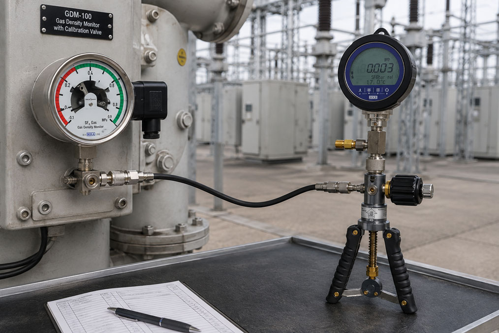
The SF₆ gas density monitor of a medium- or high-voltage switchgear system indicates a plausible value. When checked with a reference pressure gauge, the pressure also appears to be approximately correct. Does[object Object],[object Object],[object Object],[object Object],[object Object],[object Object],[object Object],[object Object],[object Object],[object Object],[object Object] this ensure that the gas density monitor is operating correctly?
Not necessarily. A gas density monitor is not an ordinary pressure gauge. Its purpose is to monitor the actual gas density as independently as possible from ambient temperature and to actuate alarm or lockout contacts at defined limit values. A simple pressure test at room temperature therefore checks only part of its functionality.
For a meaningful test, the reference value, temperature reference, indication or density value and the electrical switching points must be considered together. At the same time, opening the SF₆ gas compartment or completely removing the gas density monitor for every calibration should be avoided wherever possible.
Suitable test systems can be found under SF₆ Calibration Systems. Gas density monitors for medium- and high-voltage switchgear are grouped under SF₆ Gas Density Monitors.
Table of Contents
- Why is a normal pressure test not sufficient?
- How does temperature compensation work?
- Which reference value must be checked?
- Low-loss testing via a calibration valve
- Correctly checking alarm and lockout contacts
- Considering switching hysteresis
- How can temperature compensation be tested?
- Considering adapters, hose and dead volume
- Systematic test procedure
- Practical example from a switchgear installation
- Typical calibration errors
- Defining test and recalibration intervals
- Which calibration systems are suitable?
- Conclusion
- Frequently asked questions
Why is a normal pressure test not sufficient?
The pressure of an enclosed gas changes with temperature. If an SF₆ gas compartment becomes warmer, the pressure increases even if no additional gas has been added. If the system cools down again, the pressure decreases accordingly.
An ordinary pressure gauge would indicate this pressure change. With a gas density monitor, however, this would be problematic because the decisive factor for the safe operation of the switchgear is not the temperature-related pressure fluctuation, but the amount of gas present or the gas density.
The gas density monitor therefore compensates for the influence of temperature. In conventional mechanical versions, this is achieved by a mechanical compensation system. Electronic devices can measure pressure and temperature and calculate the density or a pressure value referenced to a defined temperature.
A test at only one ambient temperature therefore initially shows whether the indication and switching points are plausible under exactly these conditions. However, it does not prove that the temperature compensation operates correctly over the entire intended temperature range.
How does temperature compensation work?
Many SF₆ gas density instruments convert the gas condition to a reference temperature of 20 °C. This is intended to ensure that the same gas filling condition is indicated regardless of whether the switchgear is operating at, for example, 5 °C, 20 °C or 40 °C.
If the ambient temperature decreases, the actual gas pressure drops. The gas density monitor must not automatically interpret this as gas loss. Conversely, a warm gas compartment must not conceal an actual loss of density simply because the physical pressure is higher due to temperature.
This function is precisely what distinguishes a gas density monitor from a simple pressure switch.
For testing, this means that the reference value must also establish the correct relationship between pressure, temperature and gas density. A simple reference pressure gauge can verify the current pressure, but it does not automatically represent the temperature-compensated density.
Which reference value must be checked?
Before calibration, it must be clarified which variable is actually indicated or evaluated by the device under test. Depending on the instrument, this may be gas density, a pressure referenced to 20 °C or another defined gas-state variable.
Suitable digital reference instruments measure pressure and temperature simultaneously. From these values, the corresponding density value or pressure compensated to a reference temperature can be calculated.
| Test Parameter | What is checked? | Why is it important? |
|---|---|---|
| Current pressure | Actual physical pressure in the test circuit | Basis for pressure generation and comparison measurement |
| Temperature | Temperature of the device under test or test circuit | Required for assessing temperature compensation |
| Compensated density value | Gas condition referenced to a defined reference condition | Actual monitoring variable of the gas density monitor |
| Alarm contact | Switching point as gas density decreases | Early warning of beginning gas loss |
| Lockout contact | Second or critical switching point | Can trigger a protection or interlocking function |
Especially with instruments that have several contacts, it is therefore not sufficient to compare only the pointer or display value.
Low-loss testing via a calibration valve
In conventional systems, a gas density monitor often had to be isolated from the gas compartment and removed for a complete test. Every additional opening of the SF₆ system, however, increases maintenance effort and creates potential points for gas emissions or later leakage.
Modern gas density monitors can therefore be equipped with a calibration valve. When the test system is connected, the gas density monitor is isolated from the actual gas compartment. The device under test remains mechanically installed on the switchgear, but during calibration it is connected to the separate test circuit.
After the test has been completed, the calibration system is removed and the connection to the gas compartment is restored.
This method is particularly advantageous because complete removal of the gas density monitor is not required. The risk of SF₆ emissions and additional leakage points during recommissioning is thereby reduced.
For existing installations, a corresponding recalibration solution can, depending on the design, also be retrofitted between the gas compartment and the installed gas density monitor.
Correctly checking alarm and lockout contacts
A gas density monitor can indicate a completely plausible value and still have an incorrectly adjusted or shifted switching point.
The test must therefore be carried out in a controlled manner across the specified limit values. The pressure or simulated density is changed slowly until the electrical contact actually switches.
In a typical configuration, two limit values may be present. The first contact indicates the beginning of a density loss, while the second contact triggers a more critical alarm or interlock as the gas density continues to fall.
The measured switching values are compared with the specified values of the actual gas density monitor. The decisive values are not general standard values but the switching points stated on the device or in the system documentation.
During the electrical test, it must also be clearly determined which contact opens or closes at which point. Confusing normally open and normally closed contacts can result in a mechanically correct switching point while the control system interprets the signal incorrectly.
Considering switching hysteresis
A mechanical switching contact normally has a certain hysteresis. The contact therefore does not switch back at exactly the same value when the density is increased again after having been reduced.
For a meaningful functional test, the switching point should therefore be approached from both directions wherever possible.
First, the pressure is slowly reduced and the actual alarm or lockout switching point is documented. The pressure is then increased again and the value at which the contact resets is recorded.
A significant change in this difference compared with previous tests can indicate mechanical ageing, contact problems or a change in the measuring system.
It is important to change the pressure slowly. If the switching point is passed too quickly, response time, mechanical inertia and operator error can distort the result.
How can temperature compensation be tested?
On-site calibration is often carried out at an approximately constant ambient temperature. This allows the current reference value to be compared very accurately, but the complete temperature-compensation curve is not fully tested.
If the quality of the temperature compensation is to be explicitly assessed, the device under test must be checked at several defined temperatures. Suitable climatic conditioning or a temperature chamber may be required for this purpose.
At the same simulated gas density, it is then checked whether the indication and switching points remain within the permissible tolerances despite the changing ambient temperature.
Such a multi-temperature test is considerably more complex than a normal on-site functional check. The test order should therefore clearly distinguish between a comparison calibration at the current ambient temperature and a full investigation of the temperature-compensation behaviour.
Considering adapters, hose and dead volume
With SF₆ gas density monitors, an unsuitable test setup can also influence the result. Long hoses, unnecessary adapters and large dead volumes make pressure adjustment slower and increase stabilisation time.
The connection between the calibration system and the device under test should therefore be as short and straightforward as possible. All components must be suitable for the pressure range and intended test medium.
Particular attention should be paid to leak tightness. Even a small leak in the external test circuit can cause the set reference value to decrease slowly. The technician could incorrectly interpret this as an unstable switching point or a fault in the gas density monitor.
Before the actual measurement begins, the test circuit should therefore be stabilised under pressure and checked for any noticeable pressure drop.
Systematic test procedure
| Step | Test | Objective |
|---|---|---|
| 1 | Identify the instrument and specified values | Clearly define measuring range, reference temperature and contacts |
| 2 | Isolate the gas density monitor from the gas compartment | Perform the test without unnecessarily opening the SF₆ gas compartment |
| 3 | Connect the calibration system | Create a tight, short and suitable test circuit |
| 4 | Compare the initial condition | Compare indication or density value with the reference |
| 5 | Slowly reduce the pressure | Determine alarm and lockout switching points |
| 6 | Increase the pressure again | Determine reset points and hysteresis |
| 7 | Check electrical contacts | Confirm correct assignment to the plant control system |
| 8 | Remove the test system | Correctly restore the connection to the gas compartment |
| 9 | Document the result | Record actual values, specified values, temperature and deviations traceably |
This sequence checks the indication, switching function and electrical processing together. A simple comparison of the pointer value would leave important functions of the gas density monitor untested.
Practical example from a switchgear installation
At a high-voltage switchgear installation, a gas density monitor is to be checked as part of recurring maintenance. The gas compartment is in its normal operating condition and should preferably not be opened for the test.
The gas density monitor is equipped with a calibration valve. Once the calibration system is connected, the monitor is isolated from the actual SF₆ gas compartment and is now located in a separate test circuit.
First, at the existing ambient temperature, the indicated density value is compared with the digital reference. The deviation is small and lies within the specified tolerance.
The test pressure is then slowly reduced. According to the documentation, the first alarm contact should switch at a certain compensated density value. In practice, the contact switches slightly later but still within the permissible tolerance.
The second contact, however, shows a significantly larger deviation. The pointer of the gas density monitor itself remains plausible, but the lockout contact does not switch until the value has fallen significantly below the intended limit.
A simple pressure or indication check would not have detected this fault.
After the test pressure has been increased again, the reset point is also documented. The calibration system is then removed and the connection between the gas compartment and gas density monitor is restored.
This example shows why the indication and electrical contacts should always be checked together.
Typical calibration errors
A particularly common mistake is to treat a gas density monitor like an ordinary pressure gauge. The current pressure is compared with a reference pressure gauge and the test is then considered successfully completed. However, this leaves the temperature compensation and switching contacts largely untested.
Changing the pressure too quickly is also problematic. The limit values should be approached slowly so that the actual switching point can be detected reliably.
Another error is the use of incorrect setpoints. Alarm and lockout contacts can be customer-specific. Switching points must therefore not be taken from a similar instrument.
The actual test temperature must also be documented. Without a temperature value, later assessment of the compensated density value is only possible to a limited extent.
Finally, the external test circuit itself must also be considered. A leaking fitting or poorly seated adapter can cause a slow pressure drop and thereby simulate an apparently unstable gas density monitor.
Defining test and recalibration intervals
The recalibration interval should not be defined identically for every gas density monitor. Relevant factors include legal requirements, manufacturer specifications, operator standards, the importance of the measuring point and the results of previous tests.
For electrical switchgear that is subject to the requirement for a leakage detection system under the current EU F-gas Regulation, the proper functioning of that system must be checked at least every six years.
However, this does not mean that six years is automatically the correct calibration interval for every gas density monitor. Grid operators may specify significantly shorter maintenance or inspection intervals.
If the historical data, for example, shows increasing deviations in a switching contact, a shorter interval may be appropriate. With stable instruments, on the other hand, unnecessarily frequent opening or intervention in the gas path should be avoided.
A documented, risk-based inspection concept is therefore decisive.
Which calibration systems are suitable?
WIKA BCS10
The BCS10 is a compact manual calibration system for comparative testing of SF₆ gas density and pressure measuring instruments. Pressure is generated using a hand pump, while a GDI-100-D precision digital gas density indicator serves as the reference.
Its advantage for service applications lies in the compact design and the ability to adjust the required test point precisely using a fine adjustment valve. The system is therefore particularly suitable for manual testing on site, in the workshop or in the laboratory.
WIKA ACS-10
The ACS-10 is available for automated test procedures. The system automatically generates the test pressure and can check gas density and pressure measuring instruments using defined test sequences.
Especially when a large number of recurring tests are required, an automated procedure reduces operator influence and simplifies consistent documentation.
GDM-100 and GLTC-CV
The WIKA GDM-100 is available in a version with an integrated calibration valve. This allows the gas density monitor to be isolated from the gas compartment for functional testing without having to remove it completely.
For already installed gas density monitors, the GLTC-CV is available as a corresponding retrofit solution. It is installed between the gas compartment and gas density monitor and likewise enables a calibration system to be connected.
Under SF₆ Calibration Systems, you will find corresponding solutions for testing gas density measuring instruments. Gas density monitors and suitable versions are grouped under SF₆ Gas Density Monitors.
ICS Schneider Messtechnik provides support in selecting calibration systems, connection adapters and gas density monitors as well as in designing low-loss test concepts for medium- and high-voltage switchgear.
Conclusion
An SF₆ gas density monitor should not be tested solely by comparing the current pressure value. Its actual task is to monitor gas density with temperature compensation and to reliably actuate defined alarm and lockout contacts.
A proper calibration therefore checks the indication or density value, reference pressure, temperature, switching points and hysteresis together.
Test connections or calibration valves that allow the gas density monitor to be isolated from the gas compartment are particularly advantageous. This enables testing without complete removal and reduces the risk of unnecessary SF₆ emissions.
However, an on-site test at a single ambient temperature does not automatically verify the complete temperature compensation. If this function is to be fully assessed, measurements at several defined temperatures are required.
The electrical contacts must not be overlooked either. A gas density monitor can indicate the correct value while still having a shifted alarm or lockout switching point.
For traceable maintenance, the specified values, actual values, test conditions, temperature, switching hysteresis and result of each contact should therefore be documented.
This allows the function of the gas density monitor to be checked without unnecessarily accessing the SF₆ gas compartment for every calibration.
Frequently asked questions about calibrating SF₆ gas density monitors
Can I simply test a gas density monitor with a pressure calibrator?
The current pressure can be compared in this way. For a complete assessment, however, temperature compensation, density reference and electrical switching contacts must also be considered.
Why is temperature important during the test?
The actual SF₆ pressure changes with temperature. The gas density monitor is intended to compensate for this change and evaluate the actual gas filling condition or gas density.
What temperature is a gas density monitor normally referenced to?
For many SF₆ gas density instruments, the pressure or gas condition is referenced to 20 °C. However, the specification of the actual instrument is always decisive.
Can a gas density monitor indicate correctly and still have a fault?
Yes. Alarm or lockout contacts in particular can be shifted even though the indicated value still appears plausible.
What is switching hysteresis?
It is the difference between the switching point during pressure reduction and the reset point when the test pressure or simulated gas density is subsequently increased again.
Can a gas density monitor be calibrated without removing it?
Yes, provided a suitable calibration or recalibration interface is available. This allows the monitor to be isolated from the gas compartment and tested with an external calibration system.
Is the test then completely free of gas loss?
The objective is to perform the test with as little emission as possible. A calibration valve prevents unnecessary removal and significantly reduces the risk of SF₆ emissions. Technically, it is therefore more appropriate to refer to low-loss or emission-minimised testing.
How can I fully test the temperature compensation?
The gas density monitor must be tested at several defined temperatures and comparable density conditions. A single measurement at room temperature evaluates only the current operating point.
How often must a gas density monitor be tested?
The specific interval depends on legal requirements, operator requirements, manufacturer specifications and the criticality of the measuring point. For certain electrical switchgear installations, the current EU F-gas Regulation requires a functional check of the prescribed leakage detection system at least every six years.
Which device is suitable for manual on-site testing?
One example is the WIKA BCS10 with hand pump and digital gas density reference indicator. The ACS-10 is available, among other systems, for automated testing.