


During pneumatic pressure calibration, a test point is often approached as quickly as possible. A pressure controller may, for example, regulate from 0 bar to 10 bar within a short period of time. The display reaches the setpoint and, at first glance, the test point appears to be stable. A few seconds later, however, the measured pressure begins to decrease slowly. The same effect can be observed when pressure is generated manually with a hand pump: the required pressure is adjusted precisely, but then drops slightly again and appears to require readjustment.
In both cases, the obvious assumption is often that the pneumatic system is leaking. This may indeed be the cause, but it does not necessarily have to be. With gaseous pressure media, pressure, temperature and volume are directly linked. When a gas is compressed quickly, not only its pressure but also its temperature increases. Once compression has ended, the heated gas begins to transfer heat to the device under test, the lines, adapters, the pressure controller and finally the surrounding environment. As the gas temperature moves back toward thermal equilibrium, the pressure also changes.
The opposite effect occurs during a rapid pressure reduction. The expanding gas initially cools down. It then absorbs heat again from its surroundings. In a largely closed volume, the pressure can therefore rise slightly again after the lower setpoint has been reached. Especially in high-accuracy pressure calibration, these changes are not merely of theoretical interest. They can be larger than the permissible measurement uncertainty of the entire calibration setup and therefore directly influence which measured value is recorded at the test point.
The magnitude of this effect does not depend solely on the pressure range. The size of the pressure step, the connected gas volume, the device under test, the length and elasticity of the pressure lines, the ambient temperature and the type of pressure generation also play a role. A compact setup with short stainless-steel lines therefore behaves differently from a system with several meters of flexible pressure hose and a device under test with a large internal volume.
Thermal pressure drift becomes particularly critical during leak testing. In this case, the pressure change over time is itself the measured quantity. If the actual leak measurement begins immediately after rapid compression, the subsequent cooling of the gas may appear to be a leak even though the test setup is actually tight.
For reliable pneumatic pressure calibration, it is therefore not sufficient for the setpoint merely to have been reached on the display. The condition of the entire pneumatic system is decisive. The actual calibration value should only be recorded once the pressure, gas, lines, device under test and reference have stabilized sufficiently.
Why Does Gas Temperature Affect Pressure?
Pressure, temperature and volume of a gas are physically linked. For many practical considerations in pneumatic calibration, this relationship can initially be described using the ideal gas law p · V = n · R · T. Here, p represents absolute pressure, V the gas volume, n the amount of substance, R the universal gas constant and T the absolute temperature.
For calibration practice, it is particularly important that a change in gas temperature directly affects the absolute pressure when the volume remains largely unchanged and the amount of gas is constant. This is exactly why a pneumatic system can continue to drift after a pressure step even though no valve is being operated and no gas is visibly being supplied or released.
Heat exchange does not take place only between the gas and the room air. The gas is in contact with the internal surfaces of pressure lines, fittings, valves, adapters and the device under test. Each of these components has its own temperature and heat capacity. After a rapid pressure change, a complex thermal equalization process therefore takes place throughout the entire test setup.
During normal process measurement, such effects often remain unnoticed because they are small compared with the permissible measurement error. In high-accuracy calibration, however, the situation can change completely. If the reference and device under test are to be evaluated within a few hundredths or thousandths of a percent, even a small temperature-induced pressure trend can already represent a relevant portion of the measurement uncertainty.
What Does Adiabatic Compression Mean?
An adiabatic change of state is ideally defined as a process in which no heat is exchanged with the surroundings during the change itself. A real pneumatic calibration setup does not, of course, meet this condition perfectly. However, if the gas is compressed within a very short period of time, there is little time during the process for heat to be transferred to the surrounding components. The process therefore temporarily approaches adiabatic behavior.
The work used to compress the gas increases its internal energy. As a result, its temperature rises. As soon as rapid compression ends, the gas begins to release heat to the cooler surfaces of the test setup. This process can take considerably longer than the actual pressure increase.
This is precisely where a typical source of error arises. A modern pressure controller can reach the required pressure within a few seconds. This does not automatically mean that the gas temperature has stabilized within the same period. The setpoint may already have been reached while the thermal condition of the system is still changing.
What Happens During a Rapid Pressure Increase?
During a rapid pressure increase, the gas is compressed or additional gas is introduced into the test volume. With a manual hand pump, this occurs, for example, through piston movement or by reducing the volume using a fine adjustment screw. An automatic pressure controller, by contrast, supplies gas from its pressure source in a controlled manner until the required setpoint is reached.
In both cases, the gas can be warmer than the rest of the test setup immediately after pressure generation. If, for example, a system is brought from approximately atmospheric pressure to 20 bar within a short period of time, a temporary thermal condition initially develops. The gas then begins to transfer heat to the pressure line, pressure connection, device under test and controller.
In a closed system, this cooling typically results in a falling pressure. With an automatic pressure controller, this effect is less obvious to the operator. The control system detects the resulting pressure drop and supplies small additional quantities of gas. The setpoint therefore remains nearly constant even though thermal equilibrium is still developing in the background.
This distinction is important when very high accuracy is required. A stable display initially means only that the control system is maintaining the pressure within its specified limits. It does not automatically prove that the gas, lines and device under test have already reached complete thermal equilibrium.
What Happens During a Rapid Pressure Reduction?
A rapid pressure reduction generally produces the opposite effect. The gas expands and initially cools down. Once the lower pressure point has been reached, the gas absorbs heat from the warmer surrounding components. In a largely closed volume, the pressure can therefore rise slightly afterwards.
This is especially important during an ascending and descending calibration sequence. While a test point in the ascending sequence may initially tend toward a falling pressure after compression, the same pressure point in the descending sequence may show a rising trend after expansion. If the values are recorded immediately after reaching the setpoint, an apparent difference may arise between the two measurement sequences that is not entirely caused by hysteresis of the device under test.
| Previous Process | Thermal Condition Immediately Afterwards | Possible Pressure Trend | Practical Consequence |
|---|---|---|---|
| Rapid compression | Gas initially warmer than the surroundings | Pressure may fall during cooling | Do not record the measured value immediately |
| Rapid expansion | Gas initially colder than the surroundings | Pressure may rise during warming | Allow stabilization during the descending sequence as well |
| Thermal equilibrium | Gas and test setup largely equalized | Only minor residual drift | Suitable condition for recording the measured value |
Why Does the Pressure Drift After a Pressure Step?
A real calibration setup does not consist of a single enclosed gas volume. Pressure lines, fittings, adapters and possibly manifolds are normally located between the pressure controller and the device under test. The device under test also has an internal volume. The pneumatic system therefore extends from the control valve of the pressure generator into the final gas-filled passage inside the connected instrument.
After a rapid pressure step, several processes take place simultaneously within this system. The gas exchanges heat with the surrounding surfaces. At the same time, flexible lines may expand slightly, seals may settle and diaphragms in the device under test may move. As a result, the effective volume also changes slightly.
An observed pressure trend can therefore consist of several causes. One part may result from the temperature change of the gas, another from elastic changes in volume and another may actually result from a small leak. At very high measurement resolutions, these effects can become visible simultaneously.
For reliable calibration, it is therefore not enough to consider only the accuracy of the pressure reference. The quality of the entire pneumatic setup determines whether the accuracy of the reference can actually be utilized in the practical measurement.
Distinguishing Temperature Drift from Leakage
A slowly falling pressure is often immediately associated with a leak in practice. Both effects can initially look very similar on the display. However, the behavior over time provides important indications.
With a thermally induced pressure change, the drift is often greatest immediately after the pressure step. The longer the thermal equalization continues, the smaller the change becomes. The pressure gradually approaches a more stable value. After expansion, the same thermal effect can even produce drift in the opposite direction.
An actual leak behaves differently. Even after the system has largely reached thermal equilibrium, gas continues to escape. The pressure therefore continues to change. However, thermal stabilization and leakage can occur simultaneously, which can make the initial phase of a measurement particularly difficult to interpret.
| Observation | Thermal Stabilization | Leakage |
|---|---|---|
| Largest change | usually immediately after the pressure step | may continue continuously |
| Behavior over time | drift normally decreases | pressure loss continues |
| After rapid expansion | pressure may rise again | a leak fundamentally continues to cause gas loss |
| Stable final condition | increasingly reached with sufficient waiting time | no permanent pressure stability with a relevant leak |
| Assessment | first allow stabilization | then evaluate the leak rate |
Especially when very small permissible leak rates are involved, a clear separation of the measurement phases is essential. If leak evaluation begins immediately after pressure generation, a completely tight device under test may appear to have a significant leak rate. Only once the thermal drift has sufficiently subsided does the remaining pressure change become more meaningful.
How Does an Automatic Pressure Controller Behave?
An automatic pneumatic pressure controller can actively compensate for the effects of thermal equalization. If the pressure drops after rapid compression, the controller detects the deviation and supplies a small additional amount of gas. If the pressure rises after expansion, the controller can release gas accordingly. The setpoint therefore remains considerably more constant than in a completely closed manual system.
This automatic readjustment is a major advantage of modern pressure controllers. The operator does not need to keep correcting the pressure with a fine adjustment screw, and automated calibration sequences can move reproducibly from one test point to the next.
Nevertheless, the connected external volume remains an important influencing factor. The controller must respond to all thermal and mechanical changes occurring in the lines and the device under test. A compact pressure transmitter connected via a short line can therefore often be stabilized faster than a large-volume device under test connected through several meters of hose.
When high accuracy is required, a defined stability or ready criterion should therefore be fulfilled in addition to reaching the setpoint. Only then can it be ensured that the remaining pressure change is small enough for the required measurement uncertainty.
Why Is the Effect Particularly Visible with Hand Pumps?
A manual pressure calibration pump has no automatic readjustment. Once the required pressure has been set, the system is largely closed. Any thermally induced pressure change is therefore displayed directly on the reference instrument.
A typical example is that a pressure of 10 bar is adjusted and then slowly drops to 9.98 or 9.97 bar. The operator corrects the pressure back to exactly 10 bar, after which another small drift occurs. This behavior is quickly interpreted as a leak even though it may at least partly be caused by thermal stabilization.
A common operating error is to immediately correct every small pressure change. Each correction compresses or expands the gas again and therefore generates another thermal transition. In demanding measurements, this can create a kind of cycle in which the system never really settles.
It is often more effective to first observe the trend after roughly approaching a pressure point. Only once the largest drift has subsided should a small correction be made using the fine adjustment control. A further short stabilization period should then follow before the measured value is documented.
What Influence Does Pneumatic Volume Have?
The connected gas volume influences both the control speed and the thermal behavior of pneumatic calibration. The total volume includes more than just the visible hoses. Internal passages in adapters, manifolds, reference instruments and the internal volume of the device under test must also be taken into account.
A larger volume contains a greater quantity of gas. To increase the pressure, more gas must therefore be introduced or compressed to a greater extent. During pressure reduction, more gas must again be removed from the system. This not only increases the actual control time, but often also the subsequent thermal stabilization time.
The geometry of the volume also plays a role. A compact metal volume has different heat-transfer characteristics from a long, thin pressure hose. Two systems with a similar total volume may therefore still show different stabilization times.
For precise calibration, a setup that is as compact as practicable is therefore advantageous. This does not mean that lines should always be made as small as technically possible. Safety, pressure range, permissible flow conditions and mechanical design must still be taken into account. However, unnecessary dead volume should be avoided.
Why Short Lines Improve Stabilization
Flexible pressure hoses influence test behavior more strongly than their simple function as connecting elements might suggest. First, a long hose increases the gas volume. At the same time, the hose wall is elastic and can expand slightly under pressure. This causes the system volume to increase somewhat during pressure generation.
In addition, a long hose has a relatively large surface area. The gas contained within it can therefore exchange heat intensively with the surroundings. If one section of the hose is exposed to an air stream while another section rests on a warm instrument surface, different temperatures can develop within the same pneumatic system.
Short and pressure-stable line routes are therefore advantageous for high-accuracy applications. Stainless-steel tubing or high-quality calibration hoses can improve mechanical stability. At the same time, unnecessary manifolds, extensions and adapters should be reduced. Each additional connection not only increases the volume but also creates another potential leak point.
Several meters of unused hose coiled on the laboratory bench should therefore not be regarded as a neutral part of the setup. If the hose is not required for the application, removing it can improve both control speed and stability.
The Device Under Test Is Part of the Pneumatic System
The stabilization time does not depend solely on the pressure controller. The connected device under test also has a major influence on behavior. A compact pressure transmitter may have only a very small internal volume. A mechanical pressure gauge, differential pressure transmitter or instrument with additional internal pressure passages may, by contrast, have a considerably larger volume.
This difference becomes particularly clear when several devices under test are connected at the same time. Each additional sensor introduces further lines, adapters and internal cavities into the system. The pressure controller must therefore regulate a larger volume and respond to additional thermal effects.
Diaphragms can also play a role. When pressure is applied to a diaphragm, it deforms slightly and thereby changes the effective gas volume. In conventional process calibration, this effect is often small. With very high measurement resolution, however, it can become visible together with hose elasticity and temperature drift.
A statement that a controller stabilizes, for example, “within a few seconds” can therefore only be interpreted under defined conditions. In a real calibration setup, the actual time results from the interaction between pressure controller, pressure range, pressure step, line system and device under test.
Local Temperature Differences in the Measuring System
For simplified calculations, it is often assumed that all of the gas in the test setup has the same temperature. In a real calibration laboratory, however, this is not necessarily the case. One section of the line may lie on a cold metal bench while another passes directly next to a warm electronic instrument. A pressure transmitter may heat itself during operation while the connected line is simultaneously cooled by the air-conditioning system.
The operator can also introduce heat into the system. If a small device under test or thin-walled pressure line is held by hand for a prolonged period, its temperature rises. During normal industrial measurement, this is usually insignificant. With a high-resolution calibration system, however, small pressure changes can become visible.
A high-quality calibration workstation should therefore provide ambient conditions that are as uniform as possible. Direct sunlight, heaters, strong air currents or strongly fluctuating room temperatures are unfavorable. The device under test should also be given sufficient time to adapt to the ambient temperature before calibration begins.
How Long Should You Wait After a Pressure Step?
A general answer such as “always wait ten seconds after each pressure point” is too simplistic for precise calibration. The required time depends on the complete setup. A small pressure step on a compact sensor can become sufficiently stable within a short period of time. A step from almost 0 to 100% of the measuring range with a large external volume can require considerably longer.
The necessary waiting time is influenced, among other things, by the pressure level, the size of the pressure step, gas volume, line arrangement, device under test and required measurement uncertainty. The method of pressure generation is also important. An automatic controller can compensate for pressure deviations during thermal equalization, while a manual system displays these changes directly.
For repeated calibrations using the same setup, a fixed waiting time can certainly be useful. However, it should first be verified experimentally. If several calibration runs demonstrate that a particular test point reliably reaches the required stability limit after 20 seconds, this time can be used in a standardized test procedure.
For high-accuracy applications, however, the elapsed time alone is not decisive. What matters is how much the pressure is still changing at the end of that time.
Stability Criterion Instead of a Fixed Waiting Time
A stability criterion evaluates not only how much time has passed since the setpoint was reached, but also how the pressure actually behaves within a defined time window. For example, it can be specified that a test point is considered stable only when the pressure changes by less than a defined limit during a particular period.
This limit must match the measurement task. With a simple process pressure gauge that has a comparatively large permissible measurement error, a small residual drift may be completely insignificant. With a high-accuracy reference transmitter, the same change may already represent a substantial portion of the permissible uncertainty.
| Influencing Factor | Effect on Stabilization | Practical Consequence |
|---|---|---|
| Large pressure step | stronger thermal transition possible | allow more stabilization time |
| Large external volume | slower control and thermal equalization | reduce unnecessary dead volume |
| Long flexible hose | more volume and additional elasticity | keep the line route as short as possible |
| Very high accuracy requirement | less residual drift permissible | use a stricter stability criterion |
| Small pressure steps | smaller thermal transition | a step-by-step calibration sequence may be advantageous |
| Stable ambient temperature | better reproducibility | avoid heat sources and drafts |
A sensibly defined stability criterion can also make automated calibration more efficient. Instead of waiting, for example, a fixed 60 seconds at every test point, the next step can begin as soon as the pressure is actually stable enough. Small pressure steps can therefore be completed faster, while larger thermal transitions automatically receive more time.
Approaching Pressure Points in a Sensible Sequence
The sequence of test points also influences thermal behavior. A direct step from 0 to 100% of the measuring range produces a significantly larger change of state than a step from 75 to 100%. A typical stepped calibration sequence of 0 → 25 → 50 → 75 → 100% therefore reduces the size of the individual pressure steps.
The descending sequence can then be performed in reverse order. This additionally allows the hysteresis behavior of the device under test to be evaluated. However, stabilization must again be taken into account at every point.
If measurements are taken too early after compression in the ascending sequence and too early after expansion in the descending sequence, the opposing thermal trends can create apparent additional hysteresis. A clearly defined test procedure considerably reduces this risk.
Why the Effect Is Particularly Critical During Leak Tests
In normal pressure calibration, the objective is to determine the deviation of the device under test at a pressure point that is as stable as possible. During a leak test, however, the pressure change over time is itself the relevant measured quantity. Thermal effects can therefore be confused particularly easily with an actual leak.
If the test volume is rapidly brought to the required pressure, the gas is initially warmer. If the actual measurement phase begins immediately, the pressure falls as the gas cools. From the point of view of a simple pressure-decay measurement, this behavior looks exactly as though gas were escaping from the system.
A reliable leak test therefore requires a clear separation in time. First, the required test pressure is generated. This is followed by a stabilization phase during which thermal and mechanical transitions are allowed to subside to a large extent. Only then does the actual measuring window begin, during which the initial pressure, final pressure and resulting pressure change or leak rate are determined.
The required length of this stabilization phase depends on the specified leak detection limit. If only a major leak needs to be identified, small thermal changes may be insignificant. With a very small permissible leak rate, however, they can be larger than the actual effect being measured.
Practical Example: Calibrating a Pressure Transmitter up to 20 bar
An industrial pressure transmitter with a measuring range of 0...20 bar is to be calibrated pneumatically. An automatic pressure controller is used as the pressure source and reference. The device under test is connected via a short, pressure-stable line. Its 4–20 mA output signal is measured in parallel using a suitable electrical process calibrator.
Before the actual calibration begins, the controller, device under test and electrical measuring equipment are allowed sufficient time to reach thermal equilibrium. The pneumatic setup is checked for leaks. The zero point is then documented first.
The first test point is 5 bar. The pressure controller reaches the setpoint within a short period of time. Nevertheless, the value is not recorded immediately. Instead, it is checked whether the stability criterion has been fulfilled. Only once the reference pressure changes by no more than the permissible amount within the defined time window are the reference value and output signal of the transmitter stored.
The system is then set to 10 bar, 15 bar and 20 bar. The same procedure is followed after every pressure step: approach the setpoint, allow stabilization and only then record the actual measured value. For the descending sequence, the pressure is then reduced from 20 bar through 15 bar, 10 bar and 5 bar back to 0 bar.
The descending sequence in particular demonstrates why stabilization is important in both directions. After a rapid pressure reduction, the gas may initially be colder and then warm up again. If the measurement were taken immediately, this thermal pressure change could appear as an additional error of the device under test.
The complete test procedure therefore separates the characteristics of the device under test from the characteristics of the pneumatic system as cleanly as possible. Only sufficiently stabilized values are used for the calibration assessment.
What Changes at Very High Accuracy?
The more accurate the reference becomes, the more visible effects become that hardly matter during normal process measurement. Small changes in gas temperature, elastic hose expansion, seal settling or very small leaks can then represent a significant portion of the overall measurement uncertainty.
The surrounding environment also becomes more important. At very low pressure ranges or during differential pressure measurement, a difference in height between the reference and the device under test may become relevant. During absolute pressure calibration or procedures involving a barometric reference, the quality of the absolute pressure or barometric signal used must also be considered.
The consequence is important: an extremely accurate reference sensor does not automatically result in equally accurate calibration. If, for example, a high-precision pressure controller is used with a long flexible hose, fluctuating room temperature and a device under test that has not yet stabilized, the actual test setup can perform significantly worse than the specified accuracy of the controller.
As accuracy requirements increase, the design of the entire calibration process therefore becomes increasingly important. Pressure reference, pneumatic setup, thermal stability, electrical measurement and test procedure must be treated as a single measuring system.
Systematic Procedure
- Define a suitable pressure medium as well as the required pressure range and reference accuracy.
- Keep the test setup as compact as possible and avoid unnecessary hose lengths, manifolds and adapters.
- Allow the controller, device under test and electrical measuring equipment sufficient time to reach ambient temperature.
- Check the complete pneumatic setup for relevant leaks before the actual calibration.
- Approach the pressure points reproducibly and, where possible, in a sensible stepped sequence.
- Observe the pressure trend after each pressure step and measure only once the stability criterion has been fulfilled.
- When generating pressure manually, do not immediately correct every small drift; first allow the system to settle thermally.
- Document ascending and descending measurement sequences separately and provide a dedicated stabilization phase before leak testing.
Common Mistakes
- Recording the measured value immediately after the setpoint has been reached: The pressure may be under control while the gas and test setup are still changing thermally.
- Interpreting every pressure drop as a leak: After rapid compression, cooling of the gas can also cause a pressure decrease.
- Always using the same waiting time: Stabilization time and residual drift depend on the actual setup and the required accuracy.
- Using unnecessarily long pressure hoses: They increase volume, elasticity and the surface area affected by temperature.
- Failing to consider the device under test as part of the pressure system: Its internal volume and mechanical design also influence control behavior.
- Constantly readjusting with a hand pump: Each correction generates another small compression or expansion and can extend stabilization time.
- Starting leak measurement immediately after pressure generation: Thermal pressure drift can then be incorrectly evaluated as a leak rate.
- Considering only the specified accuracy of the reference instrument: The actual calibration quality is determined by the entire test setup.
Suitable Automatic Pressure Controller
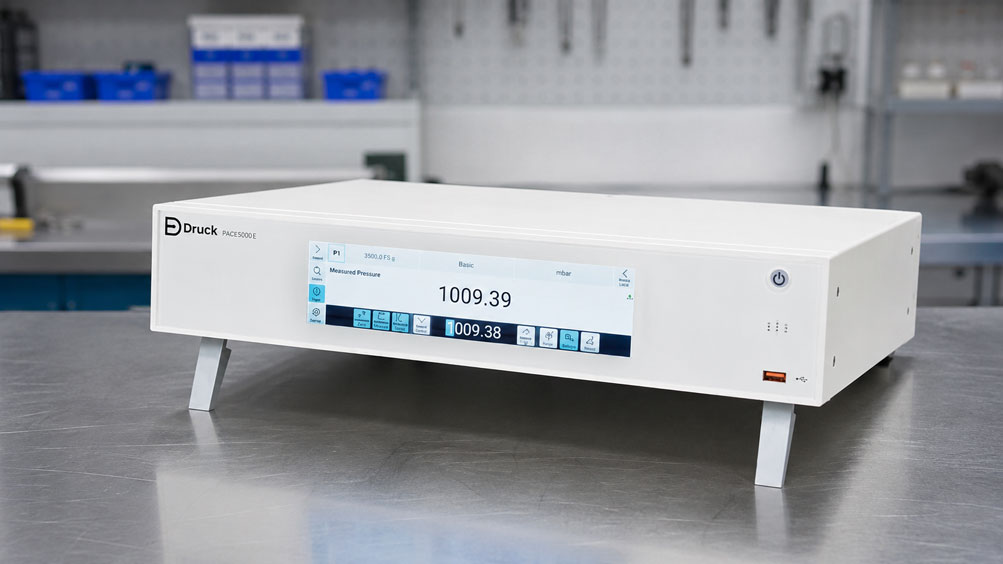
For high-accuracy and automated pneumatic pressure calibration, the Druck PACE5000E, for example, is a suitable choice. The modular pressure controller is designed for calibration laboratories, test benches, production as well as research and development, and combines fast automatic pressure control with high control stability.
Depending on the PACE CM control module installed, different pressure ranges and accuracy requirements can be covered. For particularly demanding reference applications, a PACE CM3 can be used. This makes the system particularly suitable for applications in which pressure points must not only be generated, but also set reproducibly with very low measurement uncertainty.
The active pressure control is particularly relevant to the topic discussed here. If the pressure falls after rapid compression due to thermal equalization, the controller can readjust it in a controlled manner. This allows a stable test point to be reached considerably faster than with a purely manual system.
The PACE5000E can therefore be used very effectively together with a pressure transmitter as the device under test. The pneumatic reference pressure is provided by the controller, while the electrical output signal of the device under test can, for example, be measured using a process calibrator such as the Druck UPS4E. This allows both pressure and the transmitter’s 4–20 mA output to be assessed simultaneously.
The controller’s leak test function also illustrates why a stabilization phase remains necessary. The test setup must be allowed to settle sufficiently between pressure generation and the actual evaluation so that thermal pressure changes are not incorrectly interpreted as leakage.
The basic principle therefore remains the same even in automated calibration: approach pressure → assess stabilization → record reference and DUT values. The automatic controller makes this sequence faster and more reproducible, but it cannot completely eliminate the thermodynamic processes within the connected gas volume.
Further automatic and manual pressure calibrators, pressure pumps, reference instruments and calibration systems can be found under Calibration Equipment at ICS Schneider.
Conclusion
Pneumatic pressure calibration is not automatically stable at the moment when the required setpoint first appears on the display. During rapid compression, the gas can heat up. As it subsequently transfers heat to the device under test, lines and surrounding environment, the pressure can fall again. After rapid expansion, the opposite effect occurs: the gas initially cools and the pressure can rise again during subsequent warming.
The magnitude of this thermal drift depends on the complete test setup. Pressure step, gas volume, line length, hose material, internal volume of the device under test, ambient temperature and type of pressure control all influence the behavior. Especially when high accuracy is required, these factors must not be neglected in favor of considering reference accuracy alone.
An automatic pressure controller can actively compensate for temperature-induced pressure changes and thereby provide a usable test point considerably faster. Nevertheless, a meaningful stability assessment remains necessary. This applies especially when very small measurement deviations are to be determined or leak rates are calculated from pressure changes over time.
Distinguishing between thermal stabilization and actual leakage is particularly important. A temperature-induced pressure change typically decreases as the system approaches thermal equilibrium. A real leak, by contrast, continues to cause pressure loss even afterwards.
For reliable pneumatic pressure calibration, the decisive moment is therefore not when the setpoint is first reached. The actual measuring point is reached when the remaining pressure change within the entire test setup is small enough to allow the reference and device-under-test values to be compared reliably with the required measurement uncertainty.
FAQ: Pneumatic Pressure Calibration and Stabilization
Why does the pressure fall slightly after a rapid pressure increase?
During rapid compression, the gas can heat up. After the pressure point has been reached, it releases heat to the pressure lines, device under test and surrounding environment. As the gas cools, the pressure can also fall if the volume remains largely constant. A slight pressure decrease immediately after a pressure step is therefore not automatically an indication of leakage.
Is falling pressure after compression automatically a leak?
No. With thermally induced drift, the change is often greatest immediately after the pressure step and then gradually becomes smaller. An actual leak, by contrast, can continue to cause pressure loss even after thermal stabilization is complete. In practice, both effects may be present at the same time.
What happens after a rapid pressure reduction?
During expansion, the gas initially cools down. It then absorbs heat from its surroundings. In a largely closed volume, the pressure can therefore rise slightly during warming. For this reason, sufficient stabilization must also be allowed during a descending calibration sequence.
What does adiabatic compression mean?
During ideal adiabatic compression, no heat is exchanged with the surroundings while the change of state takes place. A real pressure calibration is not completely adiabatic. During rapid pressure changes, however, there is little time for heat transfer during the actual compression, so the behavior can temporarily approach an adiabatic process.
How long should I wait after a pressure step?
There is no universally applicable waiting time. The required stabilization depends, among other things, on the pressure step, connected gas volume, line length and material, device under test and required measurement uncertainty. For precise calibration, a defined stability criterion is therefore more meaningful than a fixed waiting time.
Why does a long pressure hose affect stabilization?
A long hose increases the pneumatic volume and provides a larger surface area for heat exchange. Flexible hoses can also expand slightly under pressure. This changes the effective volume and can increase the time required to reach a stable pressure point.
Does an automatic pressure controller eliminate the need to wait?
No. An automatic controller can actively compensate for pressure changes during thermal equalization and thereby regulate considerably faster. Nevertheless, the connected gas volume still undergoes thermal equalization. When high accuracy is required, it should therefore still be verified that the defined stability condition has been fulfilled.
Why does the same controller stabilize at different speeds with different devices under test?
The device under test is part of the connected pneumatic system. Differences in internal volume, diaphragms, connections or additional lines change the total volume and therefore the control and stabilization behavior. The actual stabilization time is therefore not solely a characteristic of the controller.
Why is the temperature effect particularly problematic during a leak test?
During a leak test, the pressure change over time is the quantity being evaluated. If the gas is still cooling after rapid pressure generation, the resulting pressure loss can look like a leak. Sufficient stabilization must therefore take place before the actual measurement phase begins.
How should a leak test be structured?
The test should clearly separate pressure generation, the thermal stabilization phase and the actual measurement window. Only after sufficient stabilization should the pressure change be used to evaluate the leak rate.
Why should I avoid constantly readjusting when using a hand pump?
Every correction causes another small compression or expansion of the gas and therefore another temperature change. Continuous readjustment can consequently extend thermal stabilization. It is often more effective to first observe the trend and then make only a fine correction.
What is particularly important for high-accuracy pressure calibration?
In addition to a suitable reference, a tight and compact test setup, short pressure-stable lines, ambient temperatures that are as constant as possible and a stability limit appropriate for the required measurement uncertainty are essential. The entire pressure routing must match the accuracy of the reference being used.
Why can ascending and descending pressure sequences look different?
During the ascending sequence, the gas is initially heated by compression, while during the descending sequence it can cool as a result of expansion. The subsequent thermal stabilization can therefore act in different directions. If the values are recorded too early, this effect can incorrectly appear to be hysteresis of the device under test.
Is the effect fundamentally different with nitrogen and compressed air?
The basic relationship between pressure, temperature and volume applies to both gases. The magnitude of the actual pressure change, however, depends on the thermodynamic properties of the medium and especially on the real test setup, pressure level and speed of the pressure change.