


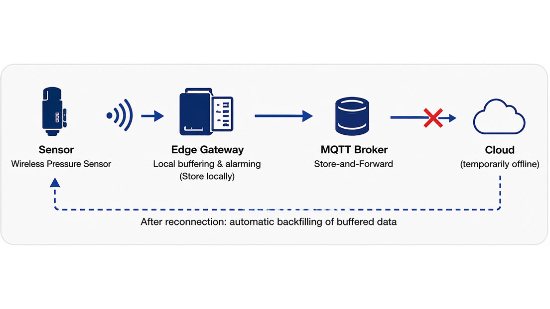
The pressure monitoring system of a plant operates reliably for months. Measured values are automatically transferred to the cloud, limit violations appear in the dashboard and maintenance personnel receive notifications. Then the internet connection fails.
The sensors continue measuring – but no new data reaches the cloud.
The system architecture now determines whether only the online dashboard is temporarily unavailable or whether alarms and measured data are lost at the same time.
A robust IIoT solution should therefore be designed so that essential functions are not created exclusively in the cloud. Measured values should be acquired locally and provided with timestamps, relevant limit-value logic should continue to operate at the edge or in the local controller where required, and data that cannot be transmitted must be buffered.
Once the connection has been restored, the buffered data can then be transferred to the higher-level system in a controlled manner.
Solutions for industrial digitalisation can be found under IIoT solutions. Applications specifically for digital pressure monitoring are grouped under IIoT pressure monitoring.
Table of Contents
- What happens during a cloud outage?
- Consider the IIoT system in layers
- Why important alarms should be generated locally
- Distinguishing between cloud alarms and safety functions
- Store-and-Forward: buffer measured values locally
- Correctly dimensioning the ring buffer
- Assign timestamps at the edge
- What MQTT QoS provides during connection interruptions
- Duplicates and sequence after reconnection
- Clearly identifying genuine data gaps
- Monitoring connection status with a watchdog
- Keeping local HMI and SCADA operational
- Distinguishing between internet, cloud and power failures
- Handling reconnection in a controlled manner
- Specifically testing communication failure
- Typical design errors
- Recommended procedure for system design
- Practical example of IIoT pressure monitoring
- Which products and solutions are suitable?
- Conclusion
- Frequently asked questions
What happens during a cloud outage?
An IIoT system normally consists of several interdependent communication paths.
For example:
Sensor → fieldbus or wireless communication → edge gateway → network → internet → cloud → dashboard or notification
If only the connection between the edge and the cloud fails, this does not automatically mean that the sensors or the local process have also failed.
The plant can continue to generate measured values.
It only becomes problematic if the system architecture assumes that every measured value must be transferred to the cloud immediately.
Without local storage, genuine data gaps can then occur during longer interruptions.
It becomes even more critical if limit-value evaluation also takes place exclusively in the cloud. A local pressure exceedance may still be measured by the sensor, but the intended alarm notification may not reach anyone during the communication failure.
Consider the IIoT system in layers
A robust architecture should clearly define which task is performed at which level.
| Layer | Typical task | Behaviour during cloud outage |
|---|---|---|
| Sensor / field device | Acquire measured value | Measurement should continue |
| PLC / edge gateway | Collect and scale data, assign timestamps, perform local logic and buffering | Local operation should remain possible |
| Local HMI / SCADA | Local display and operation | Should remain available with a suitable architecture |
| Cloud | Remote access, dashboards, reporting, higher-level analytics | Temporarily unavailable |
This separation prevents a simple communication failure from unnecessarily causing a loss of functionality across the entire measurement and monitoring chain.
Why important alarms should be generated locally
A typical mistake in new IIoT projects is to configure every limit value exclusively in a cloud dashboard.
During normal operation, this works conveniently:
- The sensor measures.
- The measured value is transmitted.
- The cloud compares the value with the limit.
- The cloud generates a notification.
However, if the internet connection is interrupted, step 2 no longer works.
For operationally relevant limits, additional local evaluation may therefore be useful.
For example:
- Pressure above 9 bar → local alarm,
- Tank level below 10 % → local warning,
- Temperature above 80 °C → local relay or PLC alarm,
- Unusually rapid change in measured value → local rate-of-change monitoring.
The cloud can additionally display and forward the same events.
However, it should not necessarily be the only place where a condition important to ongoing operation is detected.
Distinguishing between cloud alarms and safety functions
It is particularly important to distinguish between an operational alarm and a safety-related protective function.
An IIoT dashboard can be highly suitable for remote monitoring, maintenance information and status notifications.
A safety-critical shutdown, however, should not depend solely on the availability of an internet connection and an external cloud service.
If a machine or plant must automatically be brought to a safe state in the event of a hazardous condition, the required protective function must be implemented locally with the components required by the risk assessment.
The edge system can additionally record and document such conditions, but it is not automatically part of a safety-related control system.
Store-and-Forward: buffer measured values locally
A local data buffer is one of the most important functions for preventing data gaps.
The principle is often referred to as Store-and-Forward:
- The measured value is received at the edge.
- A timestamp is assigned.
- The data record is stored locally.
- Transmission to the cloud is attempted.
- If the connection is unavailable, the data record remains in local storage.
- After reconnection, it is transmitted retrospectively.
This means the sensor does not need to know whether the cloud is currently reachable.
The local edge layer decouples continuous data acquisition from potentially interrupted remote communication.
However, it is essential that the buffer is dimensioned sufficiently.
Correctly dimensioning the ring buffer
Local storage capacity is not unlimited.
It must therefore be defined in advance how long the system should be able to bridge a communication outage.
The required storage capacity depends in particular on:
- number of measuring points,
- sampling rate,
- stored variables,
- size of each data record, and
- maximum assumed outage duration.
In simplified form:
Required storage = data records per second × data record size × required buffer duration
An additional reserve should also be provided.
A ring buffer can be designed so that the oldest data is overwritten when the storage is completely full.
This prevents a complete memory overflow, but at the same time means that historical values are lost if the outage lasts too long.
A defined buffer fill level should therefore itself be monitored.
For example:
- 50 % memory utilisation → information,
- 80 % → warning,
- 95 % → critical local alarm.
The specific values must be adapted to the respective application.
Assign timestamps at the edge
A measured value should ideally be stored with the time at which it was actually acquired.
This becomes particularly important if the data does not reach the cloud until several hours later.
If the cloud server were to assign the timestamp only upon receipt, thousands of older values could appear to have been generated at the same current time after reconnection.
A robust data record structure therefore contains, for example:
- device ID,
- measured value,
- unit,
- acquisition time,
- quality or status information, and
- where applicable, a consecutive sequence number.
The time of the edge gateway must also be monitored.
After a restart without valid time synchronisation, historical measured values must not be stored unnoticed with incorrect timestamps.
What MQTT QoS provides during connection interruptions
MQTT provides different Quality of Service levels for message transmission.
In simplified form:
| QoS | Basic principle | Points to consider |
|---|---|---|
| QoS 0 | At most once | Message may be lost |
| QoS 1 | At least once | Delivery is acknowledged, duplicates are possible |
| QoS 2 | Exactly once at protocol level | Higher communication overhead |
For many industrial telemetry and alarm applications, QoS 1 is a sensible option.
However, it is important to note:
MQTT QoS does not replace a sufficiently dimensioned local measurement data buffer.
If an edge device generates new process values during a complete network outage lasting several hours, these values must be stored somewhere locally if they are to be transmitted completely at a later time.
MQTT session mechanisms and Store-and-Forward therefore perform different tasks and should not be confused with one another.
Duplicates and sequence after reconnection
Following an interrupted connection, retransmission can create additional challenges.
With “at least once” transmission, for example, messages may arrive more than once.
The target system should be able to identify such data records.
Useful information includes, for example:
- unique data record ID,
- device ID,
- timestamp, and
- consecutive sequence number.
This allows the target system to check whether a value has already been processed.
The sequence is also important.
After an eight-hour interruption, the latest value should not simply be transmitted first and then the complete old data buffer without any identification.
The evaluation system must clearly distinguish between:
- current live data and
- backfilled historical data.
Clearly identifying genuine data gaps
Even a well-designed buffer can eventually become completely full.
If older measured values are then overwritten, a genuine data gap occurs.
This should not remain hidden.
The system should document, for example:
- time of the communication failure,
- start of data buffering,
- buffer overflow,
- number of lost data records, and
- time of reconnection.
A missing data section must not later appear to be a normal period with no process changes.
Clear identification of such gaps is particularly important for quality or compliance-related data.
Monitoring connection status with a watchdog
A plant should be able to recognise that its higher-level connection has failed.
A communication watchdog or heartbeat can be used for this purpose.
The principle is simple:
Successful communication is expected within a defined period.
If this does not occur, the edge system sets a status such as:
Cloud offline / connection fault.
This status can be displayed and logged locally.
Selecting an appropriate monitoring interval is important.
For a generally non-critical application, a single lost data packet should not immediately trigger a communication alarm. Conversely, an actual connection failure must not remain unnoticed for hours.
Keeping local HMI and SCADA operational
Cloud-based visualisation offers advantages for access across multiple locations.
However, an additional local display is often useful for plant personnel.
During an internet outage, the following can, for example, remain available:
- local HMI,
- SCADA system within the plant network,
- PLC display,
- edge web interface, or
- physical signal light or relay indication.
This allows operating personnel to continue assessing whether the process is operating normally.
An unavailable cloud dashboard should not result in there being no local information at all about pressure, temperature or level.
Distinguishing between internet, cloud and power failures
At least three different situations should be tested when considering failure scenarios:
| Failure | Sensor / edge | Cloud |
|---|---|---|
| Internet connection interrupted | Available locally | Not reachable |
| Cloud service unavailable | Available locally | Service disrupted |
| Edge power supply fails | Depends on power supply / UPS | No new edge data |
A data buffer only helps during an internet or cloud outage if the edge device itself continues to receive power.
For particularly important data, the power supply of the gateway, network switches and, where applicable, the local controller can therefore also be included in the availability concept.
Handling reconnection in a controlled manner
Once the network connection returns, two tasks arise simultaneously:
- continue transmitting current measured values and
- backfill historically buffered data.
If several hours of data are transmitted at maximum speed without control, this can unnecessarily load the network, broker or cloud interface.
Controlled retransmission can therefore be useful.
The following should be defined, among other things:
- priority of current alarms,
- sequence of historical data,
- maximum backfill rate,
- acknowledgement of successfully transmitted data records, and
- deletion from local storage only after successful processing.
Alarm events in particular should not have to wait for several minutes behind large volumes of historical trend data.
Specifically testing communication failure
Whether an IIoT solution operates correctly offline should not only be discovered during the first real network outage.
A defined failure test can, for example, be performed as follows:
- Establish normal operation.
- Check measured values and cloud connection.
- Deliberately interrupt the internet or cloud connection.
- Change process measured values.
- Trigger local limits.
- Check local alarm functions.
- Observe buffer utilisation.
- Generate several measured values with a known time sequence.
- Restore the connection.
- Check backfilling of the historical values.
- Check timestamps and sequence.
- Check for duplicate data records.
- Compare cloud and local event logs.
Such a test reveals significantly more about actual system robustness than simply checking whether the dashboard displays values during normal operation.
Typical design errors
| Observation | Possible cause | Recommended action |
|---|---|---|
| Data gaps occur during an internet outage | No local buffering | Implement Store-and-Forward at the edge |
| Local limit violation is not reported | Alarm configured exclusively in the cloud | Add operationally relevant alarm function locally |
| Historical values appear with incorrect time | Timestamp assigned only upon cloud receipt | Assign timestamp during data acquisition |
| Values appear twice after reconnection | Retransmission without duplicate detection | Use unique IDs or sequence numbers |
| Gateway overwrites data after a longer outage | Buffer dimensioned too small | Calculate required buffer duration and monitor memory status |
| Cloud is offline but nobody on site notices | No communication watchdog | Monitor connection status locally |
| Network is heavily loaded after reconnection | Unlimited backfilling of buffered data | Prioritise and control Store-and-Forward |
| Data is lost during a power failure despite buffering | Edge gateway itself has lost power | Check power supply and, where applicable, UPS concept |
Recommended procedure for system design
- Define measuring points: Specify which sensor values are to be acquired.
- Determine sampling rate: Consider process dynamics and required resolution.
- Define alarm classes: Distinguish between information, operational alarm and safety-related function.
- Define local logic: Specify which limits must also be evaluated without the cloud.
- Define outage duration: Determine how long no measured data may be lost without a network connection.
- Dimension the buffer: Consider number of measuring points, data rate and reserve.
- Define the time concept: Assign timestamps during measurement acquisition.
- Define data IDs: Use device ID, timestamp and sequence number for unique assignment.
- Monitor communication status: Implement watchdog or heartbeat.
- Define local visualisation: Operate HMI, SCADA or edge interface independently of the cloud where required.
- Define Store-and-Forward: Specify behaviour during interruption and reconnection.
- Handle overflow: Clearly define behaviour when storage is completely full.
- Test reconnection: Check sequence, duplicates and backfilling.
- Document failure scenarios: Consider internet, cloud, gateway and power failures separately.
Practical example of IIoT pressure monitoring
At an industrial facility, several compressed-air lines are monitored using digital pressure sensors.
The values are read by an edge gateway and then transmitted via MQTT to a central cloud platform.
The dashboard is used for energy monitoring and reports unusual pressure drops.
The normal sampling interval is ten seconds.
On a Friday evening, the plant’s internet connection fails.
The sensors and edge system continue operating.
The gateway detects the missing cloud connection via the communication watchdog and locally sets the message “Cloud offline”.
At the same time, all new pressure values are stored in a local buffer with their original timestamps.
During the night, an unusually strong pressure drop occurs in one compressed-air line.
Because the corresponding limit value is also evaluated locally at the edge or in the controller, the warning continues to appear on the local HMI.
At this point, however, the cloud cannot send an external notification.
On Saturday morning, the internet connection is restored.
Current process values are immediately transmitted again. At the same time, the gateway begins controlled backfilling of the historical data.
The cloud receives every measured value with its original acquisition time.
The later trend therefore also shows the complete history during the network outage.
The “Cloud offline” event is also documented.
This makes it possible to clearly distinguish between:
- an actual process deviation,
- a communication outage, and
- a genuine data gap.
The example shows that the cloud can be an important part of the monitoring system, but it should not automatically be its only functioning component.
Which products and solutions are suitable?
ICS IIoT solutions – edge, MQTT and local data processing
Under IIoT solutions, ICS Schneider Messtechnik combines field devices, sensors and controllers with edge gateways as well as higher-level IT and cloud systems.
Depending on the application, measured values can, for example, be acquired via Modbus RTU, HART, IO-Link, OPC UA or Ethernet and then forwarded via MQTT or HTTPS.
For a fault-tolerant architecture, the edge layer can perform functions such as:
- measurement acquisition,
- scaling,
- timestamping,
- local limit-value evaluation,
- data buffering, and
- Store-and-Forward after reconnection.
The key is to define the required offline functions during the project planning stage.
WIKA PEW-1000 – wireless IIoT pressure monitoring
The WIKA PEW-1000 is a wireless pressure sensor for industrial gas and liquid applications.
It is particularly suitable for remote measuring points and retrofit applications where measured values are to be integrated wirelessly into an IIoT infrastructure.
The sensor represents the field and wireless layer of the measurement chain. Local alarm functions, higher-level data buffering and Store-and-Forward must be implemented at gateway, controller or edge level according to the selected overall architecture.
WIKA NETRIS®1 – wirelessly integrating existing standard sensors
The WIKA NETRIS®1 enables sensors with standard signals to be integrated wirelessly into an IIoT application.
This makes it possible, for example, to integrate existing 4–20 mA or 0–10 V sensors as well as suitable resistance thermometers into a wireless architecture.
The wireless unit is therefore particularly useful for retrofitting existing measuring points.
Here too, the offline strategy of the overall system should be planned independently of how the individual measured value is transmitted from the field device to the higher-level system.
WIKA NETRIS®3 – IIoT wireless transmission for hazardous-area applications
The WIKA NETRIS®3 is available for suitable WIKA measuring instruments in hazardous areas.
The wireless unit transmits measured values via LoRaWAN® and therefore enables remote measuring points to be integrated into IIoT structures.
For the failure concept, however, it must also be considered which data should remain locally available if the wireless, gateway or cloud path is interrupted.
IDCT531i – pressure sensor with RS485 / Modbus RTU
The IDCT531i provides pressure values digitally via RS485 with Modbus RTU.
This allows the sensor to be connected directly to a PLC or edge gateway, for example.
Wired field communication can be particularly interesting when local process monitoring needs to remain available independently of the internet or cloud.
Further devices and solutions for this area can be found under IIoT pressure monitoring.
ICS Schneider Messtechnik supports you in selecting sensors, communication interfaces and edge gateways as well as with register mapping, MQTT topic structures, local alarm functions, data buffering and integration into SCADA or cloud systems.
Conclusion
An IIoT solution is only truly robust if it has a defined behaviour even when the cloud connection is interrupted.
The most important basic rule is:
Measurement, operationally relevant local alarming and necessary data storage should not be unnecessarily dependent on a permanently available internet connection.
An edge gateway can decouple the field and cloud layers.
It acquires measured values locally, assigns timestamps, executes limit-value logic where required and temporarily stores data that has not yet been transmitted.
After reconnection, the data records are backfilled via Store-and-Forward.
Duplicates, sequence and the original acquisition time must be taken into account.
MQTT QoS improves the reliability of message transmission but does not replace a locally dimensioned measurement data buffer for longer offline periods.
The buffer itself must also be monitored. If it becomes full, it must be clearly defined whether old data is overwritten, new data is discarded or a local alarm is triggered.
Finally, practical failure testing is particularly important.
Only a deliberate interruption of communication shows whether local alarms actually continue to function, measured values are retained and the cloud receives a complete and chronologically correct history after reconnection.
Frequently asked questions about IIoT during cloud outages
What happens to IIoT measured values if the internet fails?
This depends on the system architecture. Without local storage, values can be lost. With a sufficiently dimensioned edge buffer, they can be stored locally and transmitted retrospectively once the connection has been restored.
What does Store-and-Forward mean?
Store-and-Forward means that measured values are first stored locally when the target system is unavailable. After the connection has been restored, the buffered data records are automatically backfilled.
Should alarms be generated in the cloud or at the edge?
For purely remote information, cloud-based evaluation may be sufficient. Operationally relevant alarms that must remain available during a communication failure should additionally be evaluated locally at the edge or in the controller.
Is MQTT QoS 1 sufficient to prevent data loss?
QoS 1 improves the delivery reliability of individual MQTT messages and operates according to the “at least once” principle. However, a suitable local storage system is still required for new process data generated during a longer offline period.
Why can duplicate values occur with MQTT QoS 1?
With “at least once”, a message can be transmitted again if successful delivery has not been clearly acknowledged. Applications should therefore be able to reliably identify data records that have already been processed.
How large should an edge data buffer be?
This depends on the number of measuring points, sampling rate, data record size and maximum required offline duration. Sufficient storage reserve should also be provided and buffer utilisation should be monitored.
Why should timestamps be assigned locally?
This ensures that data transmitted later can still be assigned to its actual acquisition time. Assigning a timestamp only when the cloud receives the data would distort the historical trend.
What happens when the local ring buffer is full?
The behaviour must be defined during project planning. Depending on the concept, the oldest data may, for example, be overwritten. An impending or actual buffer overflow should be clearly logged and reported.
How does the system detect a cloud outage?
A communication watchdog or heartbeat can typically be used. If the expected communication does not occur within a defined period, the connection status is locally detected as faulty.
How do I test the offline functionality of an IIoT system?
The connection should be deliberately interrupted while defined measured values and alarms are generated. Local alarming, data buffering, timestamps, reconnection, backfilling, sequence and possible duplicates should then be checked.