


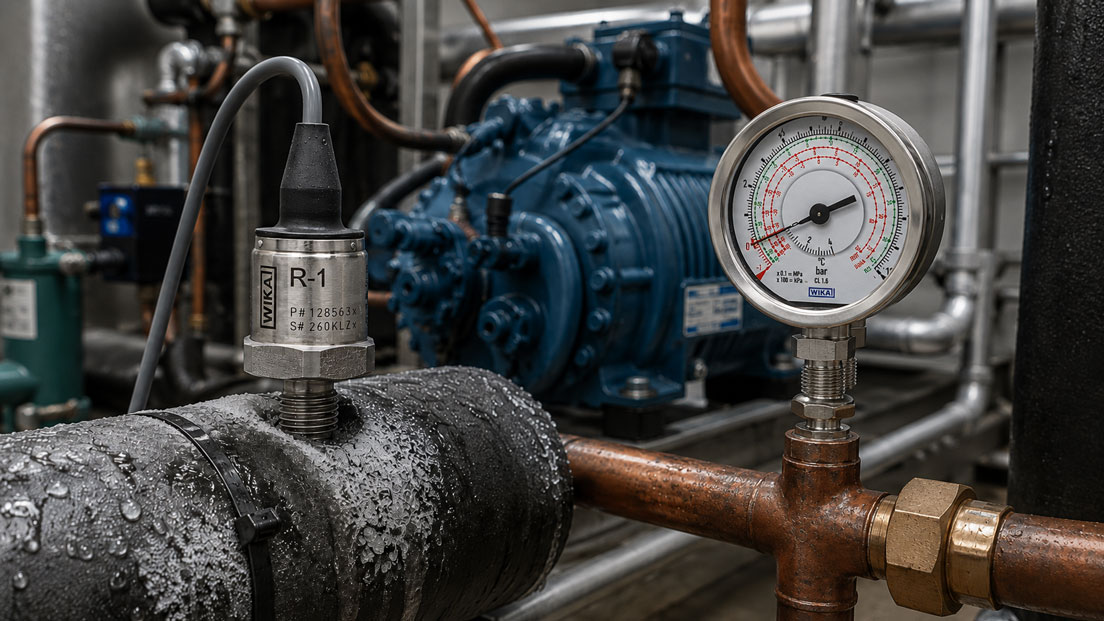
A pressure sensor on the high-pressure side of a refrigeration system shows plausible values while the system is at a standstill. As soon as the compressor starts, however, the signal begins to fluctuate. A pressure gauge installed next to it visibly vibrates, while condensation forms on the sensor housing. A few months later, the measuring point fails completely.
Such problems do not necessarily mean that the pressure sensor itself is fundamentally unsuitable. Refrigeration systems combine several demanding operating conditions at the same time: high and low pressures, rapid pressure changes, compressor pulsations, cold pipework, condensation, refrigerants and refrigeration oils, as well as high requirements for leak-tightness.
A reliable pressure measuring point must therefore be considered as a complete system. Measuring range, wetted materials, seals, process connection, temperature range, overpressure resistance and dynamic behaviour must all be suitable for the actual measuring point.
Suitable electronic measuring instruments can be found under Pressure sensors / differential pressure sensors. Mechanical and digital pressure indicators are grouped under Pressure gauges / digital pressure gauges.
Table of Contents
- Distinguishing between the high- and low-pressure sides
- Selecting the correct measuring range and overpressure resistance
- Correctly assessing refrigerant compatibility
- Why refrigeration oil must also be considered
- Compressor pulsations and pressure oscillations
- When is damping useful?
- Do not confuse pressure spikes with normal operating pressure
- Low temperatures and condensation
- Process connection and installation position
- Leak-tightness of the measuring point
- Using service connections correctly
- Gauge pressure, absolute pressure and refrigerant data
- Why pressure measurement alone is not sufficient
- Typical fault patterns
- Recommended procedure for sensor selection
- Calibration and functional testing
- Practical example from a heat pump
- Which products and solutions are suitable?
- Conclusion
- Frequently asked questions
Distinguishing between the high- and low-pressure sides
The pressure is not the same throughout a refrigeration circuit. When selecting the measuring instrument, it must therefore first be determined where the measurement is to be taken.
The high-pressure side typically includes the compressor outlet and the condenser or gas cooler. Comparatively high operating pressures, elevated temperatures and pronounced pressure pulsations can occur here.
The low-pressure side typically includes the section downstream of the expansion device, through the evaporator and up to the compressor suction line. The pressures are lower, but the pipework and measuring point can become very cold.
A sensor that operates without problems on the low-pressure side is therefore not automatically suitable for the high-pressure side.
Different measuring ranges may also be required within the same system.
Selecting the correct measuring range and overpressure resistance
A common mistake is to select the sensor only according to the normal operating pressure.
If the typical high pressure is, for example, 25 bar, this does not automatically mean that a sensor with a measuring range up to 25 bar is the correct choice.
The following must also be taken into account:
- maximum permissible system operating pressure,
- start-up and shutdown conditions,
- high ambient temperatures,
- defrost or switching processes,
- valve switching operations,
- compressor pulsations, and
- short-term pressure spikes.
Measuring range, permissible overpressure and burst pressure are different specifications.
A sensor may, for example, withstand a short-term higher pressure without this pressure range being intended for continuous measurement. Conversely, the measuring range should not be selected unnecessarily high, as this can reduce the usable resolution within the normal operating range.
The correct selection therefore depends on the actual pressure profile of the system and the permissible loads of the specific sensor.
Correctly assessing refrigerant compatibility
The statement “stainless steel is compatible with refrigerants” is not sufficient for a complete assessment.
Depending on the design, a pressure measuring point may include:
- measuring diaphragm,
- process connection,
- internal seals,
- O-rings,
- brazed or welded joints, and
- possibly additional wetted materials.
All of these components must be compatible with the refrigerant being used.
A fully metallic or welded sensor design can be particularly advantageous if it eliminates the need for an additional elastomer seal between the measuring cell and the process connection.
Nevertheless, approval should always be checked for the specific sensor and the refrigerant actually being used.
This is particularly important with alternative or natural refrigerants and with refrigerants that impose special requirements regarding pressure, flammability or material compatibility.
Why refrigeration oil must also be considered
In a real refrigeration circuit, the pressure sensor is often not exposed exclusively to pure refrigerant.
A portion of the compressor oil is carried through the system together with the refrigerant. Depending on the measuring point and operating condition, oil may therefore also be present at the sensor process connection.
When assessing material compatibility, not only the refrigerant but also the refrigeration oil used, or the actual refrigerant-oil mixture present in the system, should therefore be considered.
Seal materials in particular can react differently to different combinations of media.
A material approval should therefore reflect the actual application as closely as possible.
Compressor pulsations and pressure oscillations
A compressor does not generate perfectly static pressure.
Depending on compressor design, speed, pipework and measuring point location, more or less pronounced pressure pulsations can be superimposed on the average system pressure.
These fluctuations can be particularly pronounced on the compressor discharge side.
On a mechanical pressure gauge, this often becomes visible as a strongly oscillating pointer.
With an electronic sensor, possible effects include:
- unstable analogue signal,
- constantly changing PLC display,
- unnecessarily frequent switching of limit values,
- strong scatter in recorded measured values, and
- increased mechanical stress on the measuring cell.
The first step is to determine whether there is actually a pressure pulsation or whether the problem is merely electrical or caused by EMC interference.
A high-resolution data logger or sufficiently fast pressure sensor can help make the dynamic pressure signal visible.
When is damping useful?
If only the average process pressure is required for control purposes, mechanical or electronic damping can be useful.
Possible measures include:
- pressure snubbers,
- restrictor orifices,
- suitable capillary lines,
- liquid-filled pressure gauges, or
- electronic filtering of the sensor signal.
Damping reduces rapid pressure changes before they reach the display or evaluation system.
This improves readability and can reduce the mechanical stress on the measuring instrument.
However, there is one important disadvantage:
Strong damping can hide real pressure spikes.
For system control, this may be exactly what is required. For root-cause analysis on a compressor, however, it may be undesirable.
Before selecting a snubber or filter, it should therefore be clear whether the average value or the actual dynamic pressure signal is required.
Do not confuse pressure spikes with normal operating pressure
Pulsation and pressure spikes are not the same thing.
A pulsation is a recurring pressure oscillation. A pressure spike, on the other hand, is a short-term and possibly isolated event.
Such spikes can occur, for example, during rapid valve switching, changeover processes or special operating conditions.
A slowly sampling measurement system may completely miss these events. The operator may then see a maximum of only 28 bar, even though the measuring point was briefly subjected to a significantly higher pressure.
If sensors are repeatedly damaged, it should therefore be checked whether the actual dynamic pressure load is known.
A sensor with suitable frequency response and sufficient sampling rate can provide much more useful diagnostic information than a heavily damped pressure gauge.
Low temperatures and condensation
On the low-pressure side of a refrigeration system, the process connection can become very cold.
The temperature is partially transferred through the metal connection to the sensor housing. If the sensor is simultaneously exposed to warm and humid ambient air, the surface temperature may fall below the dew point of the surrounding air.
The result is condensation.
At even lower temperatures, ice or frost can form.
This creates two separate requirements:
- The wetted part must withstand the actual refrigerant temperature.
- The housing and electrical connection must withstand the ambient conditions and possible condensation.
A high IP rating alone does not automatically answer all questions relating to permanent condensation. The housing design, connector, cable outlet and temperature cycling must be considered together.
Temperature cycling is particularly problematic. During system operation, a sensor may cool down significantly and then warm up again when the system is switched off. This can lead to repeated condensation and drying cycles.
Process connection and installation position
The installation position of a pressure measuring point is often selected solely according to where sufficient mechanical space is available.
For reliable measurement, however, the process conditions and pipe routing should also be taken into account.
A long, thin branch line can, for example, create additional hydraulic or pneumatic damping. At the same time, refrigerant or oil may accumulate in it.
A long adapter chain, on the other hand, increases the mechanical lever arm and creates additional potential leak points.
Where possible, the measuring point should therefore be:
- mechanically stable,
- installed with as few adapters as possible,
- equipped with a suitable process connection,
- easily accessible for service work, and
- free from unnecessary mechanical loads.
However, the specific installation position must comply with the requirements of the system and sensor manufacturer. No general installation rule should be applied to refrigeration circuits without considering the actual pipework configuration.
Leak-tightness of the measuring point
In a refrigeration system, even a small leak is not merely a measurement problem.
Loss of refrigerant can impair system function and efficiency. Depending on the refrigerant used, additional environmental or safety requirements may also apply.
Every additional adapter, fitting and service connection creates another potential leak point.
For permanently installed sensors, a design with as few sealing points as possible is therefore advantageous.
The following should be checked in particular:
- thread type,
- sealing principle,
- seal material,
- tightening or installation method,
- pipework loads, and
- vibrations.
After installation or replacement of a sensor, the measuring point should be checked for leaks in accordance with the procedure specified for the system.
Using service connections correctly
Refrigeration systems often have defined service connections for maintenance, diagnostics and comparative measurements.
These allow a reference pressure gauge or suitable electronic pressure measuring instrument to be connected without having to remove the permanently installed measuring point.
This offers several advantages:
- The sensor and system display can be compared directly.
- The process connection of the permanently installed sensor does not have to be opened.
- Faults in the sensor, control system and signal transmission can be distinguished more easily.
Service connections must, however, also be leak-tight and suitable for the respective refrigerant and maximum pressure.
The work and safety procedures specified for the refrigeration system must also be followed when connecting and disconnecting service equipment.
Gauge pressure, absolute pressure and refrigerant data
When measuring pressure, it must be clearly known whether an instrument measures or displays gauge pressure or absolute pressure.
A gauge pressure sensor references its measurement to ambient pressure. An absolute pressure sensor, on the other hand, uses an internal vacuum as its reference.
This distinction becomes relevant when pressure values are compared with thermodynamic refrigerant data or a pressure-temperature relationship.
For correct evaluation, it must therefore be ensured that the pressure value and the refrigerant table being used refer to the same pressure reference.
Especially at low pressures, confusing bar absolute with bar gauge can result in significant interpretation errors.
Why pressure measurement alone is not sufficient
Pressure is one of the most important measured variables in a refrigeration circuit, but it does not fully describe the operating condition of the system.
For many diagnostic tasks, temperature must also be measured simultaneously at a defined location.
Only the combination of pressure, refrigerant data and the actual pipe or refrigerant temperature enables a more complete assessment of the operating condition.
An incorrect temperature measurement point can be just as misleading as an incorrect pressure value.
Pressure and temperature should therefore be measured as simultaneously as possible and at technically corresponding measuring points.
Typical fault patterns
| Observation | Possible cause | Recommended check |
|---|---|---|
| Pressure gauge pointer vibrates strongly | Compressor pulsation or vibration | Check dynamic pressure and assess suitable damping |
| 4–20 mA signal fluctuates only while the compressor is running | Pressure pulsation or EMC interference | Check the pressure signal with a reference measurement and inspect the electrical installation |
| Sensor repeatedly fails on a cold suction line | Possible condensation, icing or unsuitable temperature range | Check process and ambient temperatures as well as the electrical connection |
| Sensor briefly goes over-range after compressor start | Pressure spike or measuring range too small | Record the dynamic maximum pressures |
| Measured value drifts after refrigerant replacement | Possible material or seal incompatibility | Check approval for the refrigerant and oil |
| Permanently installed sensor and service pressure gauge show different values | Calibration deviation, different pressure reference or different measuring point position | Compare both instruments under identical conditions |
| Measuring point loses refrigerant after sensor replacement | Incorrect sealing principle or damaged seal | Depressurise the connection, inspect it and reinstall correctly |
| Measured value is stable, but short pressure spikes are missing | Mechanical or electronic damping too strong | Check the measuring chain and filter settings |
Recommended procedure for sensor selection
- Determine the measuring point: Clearly define whether it is on the high-pressure, low-pressure, suction or discharge side.
- Identify the refrigerant: Document the specific refrigerant type.
- Consider the oil: Take the refrigeration oil used and possible media mixtures into account.
- Determine the pressure range: Consider normal operation, maximum operating pressure and possible pressure spikes.
- Check temperatures: Assess medium and ambient temperature separately.
- Consider condensation: Pay particular attention to cold measuring points in warm and humid environments.
- Check materials: Verify the suitability of all wetted materials and seals.
- Assess dynamics: Determine whether compressor pulsations or rapid pressure spikes may occur.
- Define damping: Use damping only if it does not distort the required measured value.
- Select the process connection: Use the most direct and leak-resistant installation possible.
- Define the output signal: For example, 4–20 mA, voltage or a digital interface according to the control system.
- Provide test access: Include a suitable service or reference measuring point.
Calibration and functional testing
Pressure sensors and pressure gauges in refrigeration systems may be exposed to significant temperature cycling, vibration and pressure changes.
Regular comparative testing or calibration is therefore advisable, particularly for measuring points that are relevant to quality or control functions.
For a simple functional check, a suitable reference measuring instrument can be connected via an intended service connection.
It is important that both instruments actually measure the same pressure and are given sufficient time to stabilise.
For a full calibration, the sensor or pressure gauge is tested at several measurement points using a suitable pressure reference.
With electronic sensors, not only the displayed process value should be considered. The electrical output signal and even the complete measuring chain up to the control system may also be relevant.
After replacing a sensor, for example, the following should be checked:
- Is the zero point correct?
- Is the measuring range correct?
- Is the output signal scaled correctly?
- Do the display and PLC value agree?
- Does the measured value respond plausibly to pressure changes?
Practical example from a heat pump
On an industrial heat pump, the pressure on the compressor discharge side is monitored using a compact 4–20 mA pressure sensor.
At standstill and at low load, the measuring point operates correctly. At high compressor load, however, the indicated pressure begins to fluctuate strongly. Several short-term fault messages occur because the upper limit is exceeded.
Initially, the pressure sensor is suspected of being defective.
A comparative measurement using a fast pressure measurement system, however, shows that pronounced periodic pressure pulsations are actually present. Short pressure spikes also occur during certain switching processes.
The original measuring point had been specified too tightly. The normal operating pressure was within the sensor range, but the dynamic loads had not been taken into account during selection.
A sensor with a suitable pressure range and sufficient overpressure resistance is subsequently installed for control purposes. Properly selected damping reduces the pulsations that are undesirable for control.
A service connection remains available for diagnostic purposes, allowing a fast reference sensor to be connected when required.
A second weak point is also identified on the cold suction line: condensation regularly forms on the electrical connector of the sensor installed there.
When replacing the sensor, attention is therefore paid not only to measuring range and refrigerant compatibility, but also to a design suitable for refrigeration applications with high resistance to condensation.
The example shows why the selection of a pressure sensor for a refrigeration system should not be based solely on a specification such as “0 … 40 bar, 4–20 mA”.
Which products and solutions are suitable?
WIKA R-1 – pressure sensor specifically for refrigeration systems and heat pumps
The WIKA R-1 was specifically developed for refrigeration and air-conditioning applications.
The measuring cell is welded directly to the process connection. No process-side elastomer seal is required. The wetted components are made of stainless steel.
The design is also specifically intended for difficult ambient conditions involving condensation.
This makes the R-1 particularly suitable for applications such as:
- refrigeration systems,
- heat pumps,
- air-conditioning systems,
- compressors, and
- condensers.
For the specific configuration, measuring range, process connection, output signal, electrical connection and the actual refrigerant being used must be coordinated.
WIKA 732.18 / 733.18 – differential pressure gauges for refrigeration applications
The WIKA models 732.18 and 733.18 are specifically intended for refrigeration systems and compressor applications.
They enable the measurement of two different pressures or differential pressure and are optionally available with combined pressure and temperature scales for refrigerants.
The liquid-filled 733.18 version is particularly useful for dynamic pressure loads and vibration. The case filling damps the indication and also helps prevent condensation inside the housing.
Pressure snubbers and accessories
For strongly pulsating measuring points, suitable pressure snubbers, valves and connection components may also be required.
The damping should, however, match the dynamics of the process and the intended measurement task. A component that is optimal for a stable operating indication may be unsuitable for analysing fast pressure spikes.
Further electronic measuring instruments can be found under Pressure sensors / differential pressure sensors. Mechanical and digital indicators are grouped under Pressure gauges / digital pressure gauges.
ICS Schneider Messtechnik supports you in selecting the pressure range, process connection, materials, output signal and accessories for refrigeration systems, heat pumps and industrial cooling processes.
Conclusion
Pressure measuring points in refrigeration systems must withstand much more than a constant static pressure.
On the high-pressure side, compressor pulsations, pressure spikes and elevated temperatures may occur. On the low-pressure side, low temperatures, condensation and icing are often the main challenges.
In addition, there is the chemical compatibility with refrigerant and refrigeration oil, as well as high requirements for the long-term leak-tightness of the measuring point.
The sensor should therefore not be selected solely according to its nominal measuring range. Overpressure resistance, materials, sealing principle, temperature limits, resistance to condensation, dynamic behaviour and process connection are also relevant.
Damping can be useful at pulsating measuring points. However, it must not be so strong that safety-critical or diagnostically relevant pressure spikes are hidden.
The combination of pressure and temperature measurement is also important. Only then can the condition of a refrigeration circuit be assessed more comprehensively.
A reliable measuring point therefore results from the combination of a suitable pressure sensor or pressure gauge, correct installation, as few sealing points as possible and a measurement strategy adapted to the actual operating conditions of the system.
Frequently asked questions about pressure measurement in refrigeration systems
Which pressure sensor does a refrigeration system require?
The sensor must be suitable for the specific measuring point in terms of measuring range, overpressure resistance, temperature, refrigerant compatibility, process connection and output signal. Different versions may be required for the high- and low-pressure sides.
Can I use a standard industrial pressure sensor with refrigerants?
Only if the manufacturer approves the wetted materials and seals used for the specific refrigerant or actual combination of media. Sensors specifically designed for refrigeration applications can offer advantages here.
Why does the pressure sensor fluctuate while the compressor is running?
A common cause is actual compressor pressure pulsation. However, electrical interference and the installation of the measuring point should also be checked.
Does a pressure snubber help against compressor pulsations?
Yes. A suitable restrictor or snubber can damp rapid pressure changes. However, damping also slows down the measurement signal and can conceal short pressure spikes.
Why does water form on the pressure sensor?
If the sensor is cooled below the dew point of the ambient air by a cold suction line, moisture condenses on its surface. At even lower temperatures, frost or ice may form.
Is IP67 automatically sufficient against condensation?
Not necessarily. Degree of protection, housing design, connector, cable outlet, temperature cycling and permanent condensation should be considered together.
Must compressor oil also be considered in addition to the refrigerant?
Yes. Oil is partially carried through real refrigeration circuits and may be present at the measuring point. The wetted materials should therefore be compatible with the actual combination of media.
Why should the pressure measuring range not be selected too tightly?
The normal operating pressure does not necessarily represent the maximum load. Start-up conditions, switching processes, pulsations and pressure spikes must also be considered.
Is a liquid-filled pressure gauge useful on a compressor?
For vibration and dynamic pressure loads, case filling can significantly stabilise the pointer movement. Whether this is sufficient for the specific measurement task or whether additional process damping is required must be assessed based on the system.
Can I determine the refrigerant temperature directly from the pressure?
Only under the relevant thermodynamic conditions and using the correct refrigerant data. It must also be clear whether absolute or gauge pressure is being used. For a complete assessment of the system, an actual temperature measurement is also required.