


A conductivity sensor has been commissioned correctly, the cell constant is set and initially the measured values agree with a reference. After a few days or weeks, however, the displayed value gradually begins to drift. The deviation is not sudden but develops slowly. After cleaning, the measurement appears to improve again – until the drift returns.
In such cases, calibration is often suspected first. A changed cell constant can indeed play a role. However, with conductivity sensors, several influences act directly on the electrical measuring path between the electrodes. Deposits change the effective surface area, air bubbles interrupt contact with the medium, temperature changes affect conductivity and unsuitable electrical operating conditions can promote electrochemical effects at the electrodes.
There is another important point: not every apparent sensor drift actually originates in the sensor. If the sample itself changes – for example through evaporation, CO₂ absorption, dosing, contamination or temperature change – a genuinely changing process value can appear to be a sensor problem.
The most important rule is therefore: When conductivity values drift, the condition of the sensor, electrode surface, temperature, sample and measuring instrument should be checked separately. Recalibration without investigating the cause may temporarily conceal the problem, but does not necessarily solve it.
How does a conductivity sensor measure?
Electrical conductivity describes how well a liquid can conduct electrical current. In aqueous solutions, dissolved ions carry this charge. In general, the more freely mobile ions are present and the more mobile they are, the higher the conductivity.
A conductivity measuring cell first measures the electrical conductance between defined electrodes. The specific conductivity is then calculated from the measured electrical behaviour and the geometry of the measuring cell.
The geometry is described by the cell constant. In simplified form:
κ = G × K
Where:
- κ = specific conductivity,
- G = measured conductance,
- K = cell constant of the measuring cell.
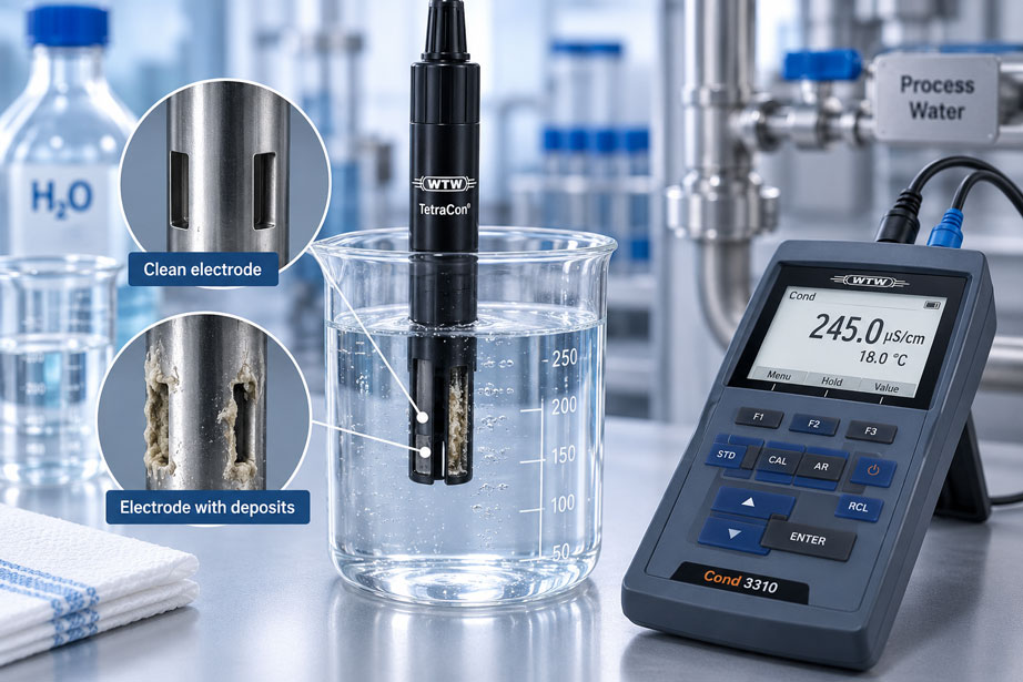
This already shows why changes to the electrodes are relevant. The calculation assumes that the actual measuring geometry corresponds to the condition for which the cell constant was determined. If part of an electrode becomes covered by scale, grease, biofilm or other deposits, the effective electrical interface changes.
The sensor may still provide a value that appears stable – but that value may no longer correspond exactly to the actual conductivity of the sample.
What does drift mean in conductivity measurement?
In practice, drift usually means that the displayed measured value changes over a longer period even though a constant process is expected. The key word here is “expected”. Without an independent reference, it is initially impossible to say with certainty whether the sensor is actually drifting or whether the medium itself has changed.
Typical observations include:
| Observation | Possible cause | First check |
|---|---|---|
| Measured value slowly increases over several days | Deposits, concentration change, evaporation or temperature compensation | Check reference sample and electrode surface |
| Measured value drops significantly after cleaning | Deposits on the measuring cell are likely | Investigate cleaning interval and medium |
| Measured value jumps or fluctuates | Air bubbles, contact problem, unstable sample or electrical interference | Check wetting and connections |
| Measured value is correct only at a particular temperature | Check temperature sensor or compensation model | Compare raw value and temperature separately |
| Reference standard is permanently displayed incorrectly | Cell constant, contamination or sensor damage | Clean the sensor and check again with fresh standard solution |
Such a symptom-based assessment is often more useful than immediately performing a new calibration. It indicates the direction in which further troubleshooting should proceed.
Why electrode deposits change the measured value
Conductivity sensors are in direct contact with the medium during measurement. As a result, substances can accumulate on the measuring cell over time. Typical examples include scale, salts, iron oxides, suspended solids, biological deposits, oil, grease or residues from cleaning and production processes.
Depending on the material, such deposits affect the measurement differently. A poorly conductive deposit can partially shield the electrical contact between the electrode and the medium. Other deposits can retain moisture or ionic residues and thereby exhibit their own electrical behaviour.
Uneven deposits are particularly critical. If one electrode surface is affected more strongly than another, not only the absolute contact area changes, but also the symmetry of the measuring cell.
At low conductivity levels, even small changes can become more noticeable because the actual measuring signal is comparatively small. A clean measuring cell is therefore particularly important in pure-water and ultrapure-water applications.
A typical indication of contamination is that the measured value returns closer to the reference value after suitable cleaning. However, this effect should not be interpreted too quickly as conclusive proof. Cleaning may also have removed air bubbles or improved wetting at the same time.
Polarisation and electrochemical effects
If a constant DC voltage were continuously applied to two electrodes in a conductive liquid, charges could build up at the interfaces and electrochemical reactions could begin. The electrode surface would then no longer behave like an ideal purely ohmic resistance.
Possible effects include polarisation, gas evolution, material reactions or deposits. As a result, the measured electrical resistance can increasingly deviate from the actual conductivity of the medium.
Modern conductivity measuring instruments therefore use suitable AC voltage or AC current methods. The periodic reversal of polarity greatly reduces electrochemical DC effects.
Polarisation nevertheless remains an important technical relationship. Among other things, it explains why electrode geometry, measuring frequency, conductivity range and measuring instrument must be matched to one another. An arbitrary electrode arrangement should therefore not simply be operated using a separate DC source or an arbitrary resistance meter.
If a sensor is being operated within its intended system, contamination, an incorrect measuring range, unsuitable cell constant, temperature or process conditions should generally be investigated first when drift occurs before unusual electrode polarisation is assumed to be the sole cause.
Check temperature and temperature compensation
The conductivity of aqueous solutions is strongly dependent on temperature. As temperature rises, the ions in many solutions move more quickly, which increases conductivity.
Conductivity measuring instruments therefore often have an integrated or connected temperature sensor. From the measured actual value, the instrument can then calculate a conductivity value referenced to a defined reference temperature.
Problems arise if the temperature measurement and conductivity measurement do not represent the same sample condition. A temperature sensor that is not immersed sufficiently, reacts with a thermal delay or has poor thermal contact with the sample can cause incorrect compensation.
The compensation model being used must also be suitable for the medium. A general linear temperature coefficient is not equally suitable for every liquid and every conductivity range.
If drift is suspected, the following should therefore be checked:
- Is the displayed temperature plausible?
- Is the temperature sensor fully immersed in the sample?
- Has the sample reached thermal equilibrium?
- Which reference temperature is set?
- Which temperature compensation method is being used?
- Is the raw value being compared or an already compensated conductivity value?
Particularly for comparison measurements, it is important that both instruments use the same reference. A value at the actual sample temperature and a value compensated to 25 °C can differ significantly even though both instruments are measuring correctly.
Air bubbles and incomplete wetting
Air conducts electrical current far less effectively than an aqueous sample. If an air bubble is located directly on an electrode surface or within the measuring geometry, part of the electrically effective area is interrupted.
Depending on the sensor design, this can produce a measured value that is too low, fluctuating or poorly reproducible. Sensors with protected electrode areas or small gaps should therefore be completely wetted and free of bubbles.
Air bubbles can arise, for example:
- when the sensor is immersed too quickly,
- in highly aerated samples,
- during pressure reduction,
- through gas release caused by a temperature change,
- at unfavourable installation positions in process pipelines.
With a portable measurement, carefully moving the sensor or gently tapping it from the side can often reveal whether a bubble is adhering to the measuring cell. With stationary sensors, however, the installation position must be selected so that gas cannot permanently accumulate on the measuring surface.
Check the cell constant and sensor geometry
The cell constant is a fundamental parameter in conductivity measurement. It links the measured conductance to the specific conductivity of the medium.
An incorrectly set cell constant therefore causes a systematic error. Errors by a fixed factor are particularly noticeable – for example if the measured value is approximately ten times too high or too low.
For some sensors, the cell constant is fixed by design. For others, it can be calibrated or set in the measuring instrument. Digital sensor systems may also automatically transfer sensor information to the instrument.
However, with slowly developing drift, an incorrect cell constant alone is less typical than with a constant scaling error. Nevertheless, it should be checked, particularly if sensors have been replaced, settings reset or measuring instruments used with different measuring cells.
Mechanical changes to the measuring cell can also be relevant. Bent, damaged or incompletely assembled electrodes alter the actual geometry. Calibration should not be used to artificially compensate for a mechanically damaged sensor.
Distinguish sample conditions from genuine sensor drift
A common troubleshooting error is to assume that the sample remains unchanged. Particularly with laboratory samples, however, conductivity can change even during the measurement itself.
Water can evaporate from open samples, increasing their concentration. Very pure water absorbs substances from containers and the surrounding environment and is particularly sensitive to contamination. CO₂ from the air can dissolve and change the ionic composition. In process samples, dosing pumps, rinsing cycles or temperature changes can cause genuine fluctuations.
The sample vessel and sampling procedure can also be relevant. Residues from cleaning agents or from a previous sample may already be sufficient to noticeably alter the result at low conductivity levels.
| Influence | Can it appear like sensor drift? | How to check |
|---|---|---|
| Evaporation | Yes, conductivity can increase | Use a fresh, closed comparison sample |
| CO₂ absorption | Particularly relevant for very pure water | Minimise contact between the sample and the environment |
| Temperature change | Yes | Check raw value, temperature and compensated value separately |
| Cleaning-agent residues | Yes, often a significant increase in conductivity | Rinse the vessel and sensor thoroughly with suitable water |
| Process dosing | Genuine change in conductivity | Compare with the process condition and a second measurement method |
| Air bubbles | Yes, often unstable or too low a measured value | Check the measuring cell for complete wetting |
Good diagnostics therefore use a fresh, defined check solution wherever possible. This allows the sensor to be separated from the actual process and assessed independently.
Clean the sensor correctly
Cleaning should be selected according to the type of contamination and the manufacturer’s instructions for the specific measuring cell. There is no universal cleaning agent that is suitable for every electrode and every deposit.
As a general principle, cleaning should be as gentle as possible and only as intensive as necessary. Mechanically aggressive brushes, abrasives or unsuitable chemicals can alter electrode surfaces and sensor geometry.
A sensible procedure is:
- Disconnect the sensor from the measuring instrument or process in accordance with the operating instructions.
- First rinse the measuring cell with clean water.
- Visually assess the type of deposit.
- Select a cleaning procedure suitable for the sensor and contamination.
- Do not unnecessarily extend the contact time of the cleaning agent.
- Rinse the sensor thoroughly afterwards.
- Completely immerse and wet the measuring cell without air bubbles in a suitable check solution.
- Allow the measured value to stabilise.
- Compare the result with a fresh standard solution or suitable reference.
Depending on the sensor, mild acidic cleaning may be specified for mineral deposits. Grease or oil deposits require a different procedure. The operating instructions for the sensor being used are always authoritative, since electrode materials and housing materials can respond differently to cleaning chemicals.
Particularly at low conductivity levels, the sensor should be rinsed carefully after cleaning. Residues of cleaning agent can otherwise produce a significantly higher conductivity than the actual sample itself.
Calibrate after cleaning or simply verify?
After cleaning, not every measuring cell should automatically be readjusted. It is initially advisable to check whether the sensor measures within the expected tolerance again using its existing cell constant.
If the check value is correct again afterwards, contamination was probably the main cause. Unnecessary recalibration could in this case merely introduce additional uncertainty.
If the sensor still deviates significantly after proper cleaning, the cell constant, standard solution, temperature and instrument parameters should be checked. Only after this is calibration or adjustment of the cell constant appropriate, provided that the sensor/instrument combination being used allows it.
Calibration should never be used to make a visibly damaged, heavily corroded or geometrically altered sensor display a “correct” value again. In such a case, the cause is mechanical and cannot be solved through software.
Distinguish between 2-electrode and 4-electrode sensors
Not every conductivity measuring cell is equally sensitive to polarisation and electrode loading. Classic 2-electrode cells use the same pair of electrodes both to supply the measuring current and to evaluate the electrical voltage.
At high conductivity levels, the influence of the electrode interfaces can therefore become more significant. 4-electrode systems, by contrast, functionally separate current and voltage measurement. This can provide robust measuring conditions over a wider conductivity range.
However, this does not mean that 4-electrode sensors cannot become contaminated. Deposits, gas bubbles or unsuitable installation conditions also change the measuring situation with these sensors.
Conversely, 2-electrode measuring cells offer clear advantages for particular applications. For very low conductivity levels, for example in ultrapure water, specially designed 2-electrode cells with a small cell constant are used.
The sensor should therefore always be selected to suit the conductivity range and medium, rather than simply according to the criterion “more electrodes = better”.
Practical example: slowly increasing measured value
In a water-treatment system, a conductivity sensor normally measures approximately 450 µS/cm. Over several weeks, the displayed value gradually rises to around 500 µS/cm. The operator initially suspects an increasing salt load in the water.
However, a portable comparison measurement on a freshly taken sample continues to show values close to the previous level. This makes a genuine process change less likely.
Visual inspection of the stationary sensor reveals a thin mineral deposit on the electrodes. The sensor is cleaned according to the manufacturer’s instructions, rinsed thoroughly and then checked in a suitable check solution.
After cleaning, the check value is once again within the expected tolerance. No change to the cell constant is required.
For the future operating strategy, the sensor is not simply calibrated more frequently. Instead, a cleaning interval is defined and at the same time the reason why deposits form more strongly at this installation point is investigated. Possible factors include temperature, flow velocity, installation position and water composition.
This means that not only the symptom is corrected, but the cause of the drift is incorporated into the maintenance strategy.
Systematic diagnostic procedure
For drifting conductivity measurements, a fixed test procedure is recommended. This prevents cleaning, calibration and instrument settings from being changed simultaneously, after which it is no longer possible to determine which action actually solved the problem.
- Check the trend: Is the deviation gradual, sudden or temperature-dependent?
- Check the process condition: Has the medium, dosing, temperature or flow changed?
- Perform a reference measurement: Preferably using a fresh sample and a suitable comparison instrument.
- Compare the temperature: Check the temperature display and compensation model.
- Visually inspect the measuring cell: Look for deposits, discolouration, corrosion or damage.
- Check wetting: Rule out air bubbles and incomplete immersion.
- Check the cell constant: Compare the sensor type and instrument setting.
- Check connections: Inspect cables, plugs and contacts.
- Clean the sensor correctly: Match the cleaning method to the deposit and sensor.
- Rinse thoroughly: Completely remove the cleaning agent.
- Check with a fresh control solution: Allow the temperature to stabilise.
- Calibrate only if necessary: Do not change the cell constant prematurely.
- Document recurring causes: Define a cleaning or maintenance interval.
This procedure separates process errors, sensor contamination and instrument parameters from one another. Particularly with recurring drift, this distinction is essential because frequent recalibration may otherwise merely conceal the consequences of a systematic problem.
Common troubleshooting errors
Recalibrating immediately whenever drift occurs
Calibration changes the relationship between the sensor signal and measured value. However, a deposit remains on the electrode. If the sensor is cleaned later, the previously adjusted cell constant may then itself cause a new deviation.
Considering only the sensor
Temperature, sample, process condition and sample vessel can also change. An independent reference measurement is therefore important.
Cleaning the electrodes too aggressively
Aggressive cleaning can alter the surface and geometry of the measuring cell. The cleaning method must be suitable for the sensor.
Failing to rinse sufficiently after chemical cleaning
Even small quantities of a cleaning agent can have a significant effect on the sample at low conductivity levels.
Overlooking air bubbles
An air bubble can reduce the electrically effective electrode area and produce unstable or excessively low measured values.
Failing to document temperature compensation
A value compensated to 25 °C cannot be compared directly with an uncompensated value at the actual sample temperature.
Trying to “repair” an incorrect cell constant through calibration
It must first be checked whether the correct sensor type or cell constant is set in the instrument at all.
Repeatedly using old or contaminated check solution
A reference check is only as reliable as the check solution being used. Contamination, evaporation or carry-over can themselves produce an incorrect comparison value.
Suitable conductivity measurement technology at ICS Schneider
ICS Schneider Messtechnik offers measuring instruments and sensors for conductivity measurement in laboratories, water treatment, environmental technology and process applications.
Conductivity measuring instruments from the WTW ProfiLine series are available, among others, for portable standard and verification measurements. The ProfiLine Cond 3310 is suitable for standard and specialised measurements and, with the appropriate measuring cell, can also be used for measurements at very low conductivity levels.
When selecting the measuring cell, the conductivity range, cell constant, temperature range, electrode design and medium are particularly relevant. A measuring cell for normal process or drinking water is not automatically optimal for ultrapure water or highly conductive cleaning media.
pH, conductivity and dissolved oxygen measurement technology at ICS Schneider
Conclusion
A drifting conductivity value is not automatically a calibration problem. The measurement depends directly on the condition of the measuring cell, the electrode surface, the temperature and the properties of the sample.
Electrode deposits, air bubbles and changing sample conditions should therefore be ruled out before recalibration. The cell constant, temperature measurement and temperature compensation also form part of a systematic diagnosis.
Polarisation and electrochemical interface effects explain why conductivity measuring instruments use specially designed AC measurement methods and why the sensor, measuring instrument and conductivity range must be matched to one another. During normal operation of a suitable system, however, visible contamination, unsuitable wetting or process changes are often the more likely causes of a gradually developing deviation.
Cleaning should always be appropriate for the material and type of deposit. The sensor is then rinsed thoroughly and first checked using a suitable control solution. Calibration or adjustment of the cell constant should only be carried out if the deviation still remains afterwards.
Following this procedure consistently avoids unnecessary adjustments and makes it easier to distinguish whether the sensor itself is actually ageing or whether only its measuring conditions have changed.
FAQ on drifting conductivity sensors
Why does a conductivity sensor drift?
Possible causes include electrode deposits, air bubbles, unsuitable temperature compensation, an incorrect cell constant, electrical contact problems, changes in the sample or a damaged sensor.
Can scale on the electrodes change the conductivity measurement?
Yes. Mineral deposits alter the effective electrode surface and the electrical contact between the sensor and sample.
Can grease or oil on a conductivity sensor cause problems?
Yes. A poorly conductive film can partially isolate the electrodes from the medium and distort the measurement.
What is electrode polarisation?
This term describes electrical or electrochemical interface effects at the electrodes. Particularly with unsuitable electrical excitation, they can affect the measured resistance.
Why do conductivity measuring instruments use AC voltage?
The periodic reversal of polarity reduces electrochemical DC effects at the electrodes and enables more stable conductivity measurement.
How can I determine whether the sensor or the sample is drifting?
A fresh, defined check solution or an independent comparison measurement helps to separate the sensor from the process.
Can an air bubble affect the measured value?
Yes. If air is present within the effective electrode area, part of the conductive liquid is displaced. This can produce a measured value that is too low or unstable.
Why is temperature so important in conductivity measurement?
Ion mobility and therefore conductivity change with temperature. The sample temperature must therefore either be taken into account or the measured value compensated to a defined reference temperature.
What is the cell constant?
The cell constant describes the geometry of a conductivity measuring cell and is used to calculate specific conductivity from the measured conductance.
Can an incorrect cell constant look like sensor drift?
An incorrect cell constant typically causes a systematic deviation rather than gradual drift. Nevertheless, it should always be checked after replacing a sensor or changing instrument settings.
Should the sensor be recalibrated after every cleaning?
Not necessarily. The first step should be to check whether the cleaned measuring cell once again measures correctly using the existing cell constant. Calibration is appropriate if a relevant deviation remains and other causes have been ruled out.
Can cleaning agent distort the measured value?
Yes. Residues of a conductive cleaning agent can cause a significant error, particularly at low conductivity levels. The measuring cell must therefore be rinsed thoroughly afterwards.
How often should a conductivity sensor be cleaned?
There is no universal interval. It depends on the medium, temperature, deposit formation, required measurement accuracy and installation conditions. A sensible interval is defined based on actual drift and contamination experience.
Is a 4-electrode measuring cell always better?
No. 4-electrode systems offer advantages in certain conductivity ranges, while specially designed 2-electrode cells can be particularly suitable for very low conductivity levels, for example in ultrapure water.
Why is ultrapure water particularly demanding for conductivity measurement?
The conductivity is very low, so small amounts of contamination, CO₂ absorption, cleaning-agent residues and temperature changes can have a comparatively large effect on the measured value.
When should the sensor be replaced?
Replacement should be considered if stable and plausible measurement is no longer possible despite correct cleaning, proper parameterisation and verification against a suitable reference, or if the electrodes or sensor geometry are visibly damaged.