


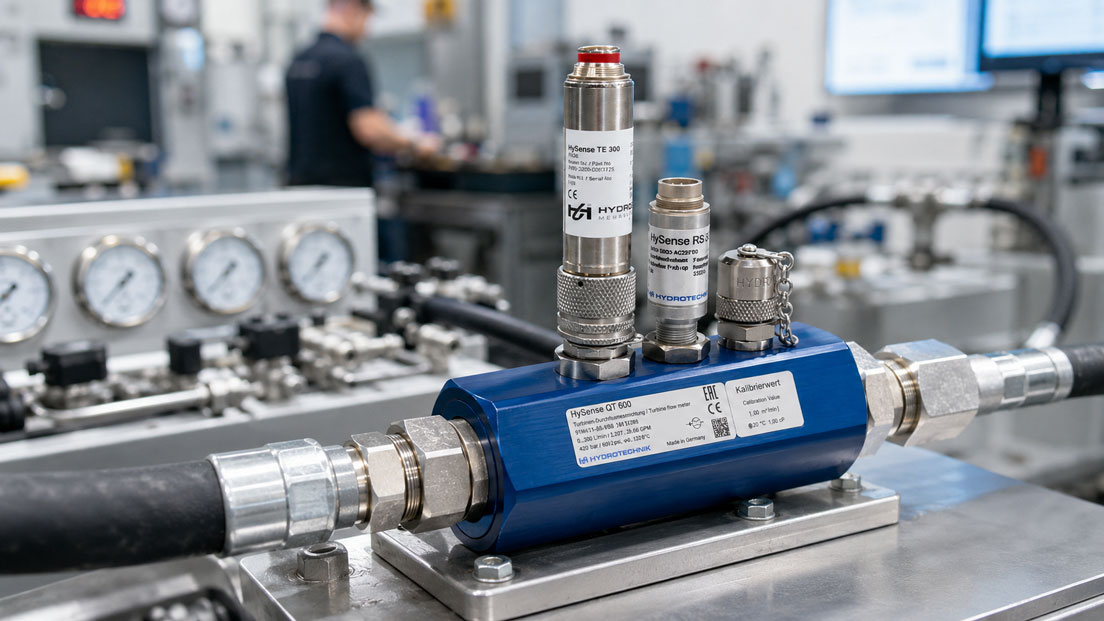
Measuring turbines are among the classic flowmeters used in industry, test bench technology, hydraulics, dosing and process measurement technology. Many users know turbine flowmeters as a robust and fast measuring solution for clean liquids. At the same time, in practice the question often arises as to whether a measuring turbine is really the right measuring principle, or whether an electromagnetic flowmeter, a Coriolis flowmeter, an ultrasonic device or an oval gear meter would be more suitable.
The answer depends heavily on the medium, viscosity, measuring range, desired output signal, pressure loss, installation situation and measuring task. A measuring turbine can be very useful when the volumetric flow of clean media needs to be measured dynamically, repeatably and with a compact sensor. However, it reaches its limits when the medium is contaminated, contains particles, is highly viscous, or when a measuring principle without moving parts is required.
This article explains in practical terms how a measuring turbine works, when it offers advantages over other flowmeters, and which points should be considered during selection, installation, calibration and signal processing.
Table of contents
- Basics: What is a measuring turbine?
- Operating principle: turbine wheel, volumetric flow and frequency signal
- Advantages of turbine flowmeters
- Limitations: When a measuring turbine is not the best choice
- Measuring turbine compared with magmeters, Coriolis, ultrasonic and oval gear meters
- Suitable media: liquids, oils, fuels and gases
- Installation, filters, pressure loss and calibration
- Output signal, PLC connection and troubleshooting
- Practical example: measuring turbine in a hydraulic test bench
- Which measuring instruments / products are suitable?
- Conclusion: When is a measuring turbine useful?
- FAQ: Frequently asked questions about measuring turbines
Basics: What is a measuring turbine?
A measuring turbine, also known as a turbine flowmeter or turbine wheel flowmeter, is a flowmeter for measuring volumetric flow. A turbine wheel or rotor is located inside the flow channel. When the medium flows through the measuring device, this turbine wheel is set into rotation. Within the specified measuring range, the rotational speed is proportional to the volumetric flow.
The sensor generates an electrical signal from this rotational movement. This is often a pulse or frequency signal that is evaluated by a display, transmitter, counter, PLC or test bench system. The faster the turbine wheel rotates, the higher the output frequency. A calibration factor, often referred to as the K-factor, assigns the number of pulses to a specific volume quantity.
This makes measuring turbines particularly interesting for applications where a fast, high-resolution and repeatable volumetric flow measurement is required. Typical examples include hydraulic test benches, dosing lines, filling processes, consumption measurements with clean media, cooling circuits, fuel measurements or test setups in mechanical engineering.
Operating principle: turbine wheel, volumetric flow and frequency signal
The measuring principle of a measuring turbine is mechanically easy to understand, but technically demanding in terms of design. The medium flows through the measuring body and hits the turbine wheel. The flow sets the rotor into rotation. Depending on the design, a sensor, for example inductive, magnetic or optical, detects the movement of the turbine blades and generates an electrical signal from it.
The decisive factor is that the rotational speed of the turbine wheel remains stable in relation to the flow within a defined range. For this to work, medium, viscosity, flow profile, bearings, nominal size and calibration must match. A measuring turbine is not an arbitrary pipeline meter that works the same way regardless of all process conditions. It is a precise measuring instrument that can deliver very good results when correctly specified.
The typical relationship is simple: the sensor generates pulses that are proportional to the quantity flowing through it. In flow measurement, this is used to calculate the current volumetric flow. In total quantity measurement, the pulses are accumulated. In test benches or dosing processes, this fast signal provision is very advantageous because changes in flow can be detected quickly.
| Term | Meaning for measuring turbines | Practical relevance |
|---|---|---|
| Turbine wheel / rotor | Rotating measuring element in the flow channel | Significantly determines response behavior, measuring range and wear behavior. |
| Pulse output | Output signal with pulses per volume unit | Ideal for counting, dosing and test bench evaluation. |
| Frequency output | Frequency increases as flow increases | Well suited for dynamic flow indication and control. |
| K-factor | Calibration value, usually pulses per liter or per volume unit | Important for accurate conversion of pulses into flow or quantity. |
| Linearity range | Range in which the output signal reliably corresponds to the flow | The measuring device should be selected so that the typical operating flow lies within this range. |
Advantages of turbine flowmeters
The most important advantage of a measuring turbine is the combination of fast response, good repeatability and compact design. Especially in test benches, hydraulic applications or dosing processes, it is important to detect flow changes quickly. The frequency or pulse signal can be evaluated directly and offers high resolution when the sensor and electronics are correctly designed.
Another advantage is its good suitability for clean, low- to medium-viscosity liquids. Depending on the version, these include water, fuels, solvents, hydraulic oils, lubricating oils or other process liquids. In such applications, a measuring turbine can be an economical and technically very convincing solution, especially when direct volume measurement is required.
Measuring turbines are also available in many sizes and connection variants. Depending on the model, there are versions for different pressure ranges, materials, output signals and installation situations. This makes them easy to integrate into test benches, machines, plant modules or process lines.
Compared with some other measuring principles, measuring turbines are often attractive when fast measured value output, a good price-performance ratio and proven technology are the main priorities. The technology is easy to understand, easy to evaluate and has been proven in many industrial applications for many years.
Limitations: When a measuring turbine is not the best choice
A measuring turbine contains a moving measuring element. This is the key difference compared with measuring principles such as electromagnetic flow, Coriolis, vortex or ultrasonic. The turbine wheel and its bearings must be able to move freely and in a defined manner. Contaminated media, particles, fibers, magnetic chips, deposits or sticky components can disturb the measurement or cause increased wear.
Viscosity also plays an important role. If the liquid is significantly more viscous than assumed during design, the flow behavior at the turbine wheel changes. This can affect linearity, response behavior and accuracy. If viscosity varies significantly, for example due to temperature changes or changing products, it should be checked very carefully whether a measuring turbine is still the appropriate solution.
Another point is pressure loss. The turbine wheel is located in the flow channel and represents hydraulic resistance. In many applications this pressure loss is not critical, but in sensitive circuits, with low available pump pressures or at very high flow rates, it must be taken into account. Installation position, flow conditioning and filtration also influence measuring quality and service life.
If the medium is heavily contaminated, contains solids, if hygienic cleaning is a priority, or if an absolutely low-maintenance measuring principle without moving parts is required, other measuring methods are often more suitable. In such cases, depending on the medium and objective, electromagnetic flowmeters, Coriolis flowmeters, ultrasonic flowmeters, vortex devices or oval gear meters may be considered.
Measuring turbine compared with magmeters, Coriolis, ultrasonic and oval gear meters
The selection of the right flowmeter does not begin with the product, but with the measuring task. Should volumetric flow or mass flow be measured? Is the medium conductive? Is it clean or contaminated? Is a fast response required? Are there moving parts in the measuring device? How high may the pressure loss be? Such questions determine whether a measuring turbine is useful or whether another measuring principle is a better fit.
A measuring turbine is often strong when clean media with sufficient flow velocity and properties that are as stable as possible are measured. Electromagnetic flowmeters, on the other hand, are very common for conductive liquids and larger pipelines, especially when no moving parts are desired. Coriolis is interesting when mass flow, density or high accuracy for high-value media are decisive. Ultrasonic can offer advantages when non-invasive clamp-on measurement or low pressure loss are the main focus. Oval gear and gear meters are particularly relevant for more viscous liquids and defined positive displacement volume measurement.
| Measuring principle | Typical strengths | Typical limitations | When particularly useful? |
|---|---|---|---|
| Measuring turbine | Fast frequency/pulse signal, good repeatability, compact design | Moving turbine wheel, more sensitive to dirt and unsuitable viscosity | Clean liquids, hydraulics, test benches, dosing, fuels, oils depending on type |
| Electromagnetic flowmeter | No moving parts, good for conductive liquids, frequently used for water and process media | Requires an electrically conductive medium, not suitable for non-conductive oils or fuels | Water, wastewater, conductive chemicals, process lines |
| Coriolis | Direct mass flow measurement, high accuracy, often additional density information | Higher costs, pressure loss and size must be checked | Dosing, recipes, high-value media, chemicals, food, pharmaceuticals |
| Ultrasonic | Low pressure loss, depending on version clamp-on measurement without intervention in the pipeline | Depends on medium, pipework, signal quality and installation situation | Retrofits, energy monitoring, large pipelines, temporary measurements |
| Oval gear / gear | Positive displacement measuring principle, well suited for many more viscous liquids | Moving parts, pressure loss and wear must be considered | Oils, lubricants, viscous media, defined quantity measurement |
Suitable media: liquids, oils, fuels and gases
Measuring turbines are used particularly often for clean liquids. The term “clean” is important here. The medium should be as free as possible from particles, fibers, deposits and magnetic contamination. Even small foreign bodies can influence the turbine wheel depending on size and bearing design or degrade the measuring quality over the long term.
With water, fuels, solvents, hydraulic oils or other low- to medium-viscosity liquids, a measuring turbine can deliver very good results, provided that material, seal, pressure range and viscosity range are suitable. With oils, special attention must be paid to the fact that viscosity can be highly temperature-dependent. A hydraulic oil behaves differently at low temperatures than in warm operating conditions. The design should therefore not be based only on a theoretical nominal value, but on the real operating range.
Measuring turbines can also be used for gases, but only with versions designed for this purpose. Gas measuring turbines differ from liquid measuring turbines in terms of design, bearings, measuring range and calibration. Compressed air and technical gases therefore cannot automatically be measured with every measuring turbine. A precise review of the data sheet and operating conditions is necessary here.
Caution is required with contaminated media, abrasive liquids, solids content, slurries or media with changing composition. In such applications, a measuring turbine is often not the first choice because the moving turbine wheel can become blocked, wear or be affected by deposits.
Installation, filters, pressure loss and calibration
Correct installation is a key factor in determining whether a measuring turbine measures reliably. A calm, as uniform as possible flow profile is advantageous. Disturbances caused by pumps, bends, valves, reducers or fittings directly upstream of the measuring device can influence the flow. Depending on the device and manufacturer’s specifications, straight inlet and outlet runs must therefore be observed.
In many applications, a filter or strainer upstream of the measuring turbine is useful or even required. The filter protects the turbine wheel and bearings from particles. The filter itself must be correctly sized so that it does not become an unintended bottleneck or significantly increase pressure loss due to contamination. Especially in test benches and hydraulic systems, the filter condition should be reviewed regularly because a clogged filter can influence the measuring result and plant operation.
The pressure loss of a measuring turbine depends on design, nominal size, flow, medium and viscosity. It should not be viewed only as a data sheet value, but in the context of the system. In a hydraulic test bench, a defined pressure loss may be acceptable, whereas it can become problematic in a weakly pumped dosing line. For sensitive media or very low flow rates, the design must be carried out particularly carefully.
Calibration also plays a central role. Measuring turbines are often operated with a K-factor or a calibration curve. For higher accuracy requirements, calibration with the actual medium or at least under operating conditions that are as similar as possible can be useful. If viscosity, temperature or measuring range differ significantly from the calibration condition, this can affect measurement uncertainty.
| Selection and installation point | Why important? | Typical practical consequence if ignored |
|---|---|---|
| Medium clean and filtered | Protects turbine wheel and bearings | Blockage, wear, unstable measured values or failure |
| Viscosity range suitable | Influences rotational behavior and linearity | Measurement deviation, poor repeatability or restricted measuring range |
| Straight inlet and outlet runs | Support a stable flow profile | Unstable frequency, fluctuating display or systematic deviation |
| Pressure loss checked | Important for pump design and process stability | Insufficient system flow, energy loss or process problems |
| Calibration factor correctly stored | Basis for converting pulses into volume | Incorrect quantity, incorrect flow or faulty dosing |
Output signal, PLC connection and troubleshooting
Measuring turbines often provide a pulse or frequency signal. This signal can be used very effectively for total quantity counting and dynamic flow measurement. In practice, however, it must be ensured that the downstream electronics can correctly acquire the signal. This includes counter input, frequency range, signal level, power supply, switching type and parameterization.
In many systems, the raw signal from the measuring turbine is not processed directly, but converted into a standard signal via a display, transmitter or signal conditioning unit. Depending on the device, this can result, for example, in a 4–20 mA signal for a PLC, a switching output, a frequency output or a digital interface. It is then important that measuring range, scaling, K-factor and unit are correctly configured.
During troubleshooting, the mechanical measuring device should therefore not be the only focus. An implausible flow value can be caused by air bubbles, contamination, incorrect installation position or a blocked rotor. However, wiring errors, incorrect input configuration, unsuitable scaling or faulty signal conversion are just as possible.
If a measuring turbine or a downstream transmitter supplies a 4–20 mA signal to a PLC or control system, the UPS4E loop calibrator can be very helpful during commissioning and troubleshooting. It allows you to check whether the current loop is working correctly, whether the PLC analog input is correctly scaled, and whether a simulated signal is plausibly displayed in the control system. This makes it easier to clearly separate mechanical flow problems from electrical signal or scaling errors.
Practical example: measuring turbine in a hydraulic test bench
A machine builder operates a hydraulic test bench for testing pumps and valves. Volumetric flows are to be measured in different operating states. The medium is a clean hydraulic oil, the operating pressure is known, and the temperature in the test bench is within a relatively stable range after a warm-up phase. The measured values should be recorded quickly and documented in the test bench computer.
In this application, a measuring turbine can be very useful. The medium is clean and filtered, the flow is within a defined range, and the fast frequency signal fits well with dynamic evaluation in the test bench. Using the calibration factor, the test bench computer can convert the pulses into volumetric flow and total quantity. If the sensor is selected to match the viscosity range of the oil, good repeatability can be achieved.
However, if the same test bench were operated with heavily contaminated oil, changing media or very low flow rates, the selection would have to be reassessed. A clogged filter, a rotor loaded with particles or a strongly changed viscosity could significantly influence the measurement. In this case, another measuring principle or adapted medium conditioning might be required.
This example shows that a measuring turbine is not simply “good” or “bad”. It is very good when the boundary conditions match its measuring principle. Especially in test benches, hydraulic systems and clean dosing processes, it can be a technically convincing and economical solution.
Which measuring instruments / products are suitable?
For applications with turbine flowmeters, ICS Schneider Messtechnik offers a dedicated category for measuring turbines. There you will find solutions for different flow ranges, media, connection types and signal variants. Selection should always be based on the specific operating data, especially medium, temperature, pressure, viscosity, measuring range, installation situation and desired output signal.
The higher-level category flow measurement technology is useful if it is not yet clear whether a measuring turbine is really the appropriate measuring principle. Various measuring methods can be classified there, for example measuring turbines, electromagnetic flowmeters, Coriolis/vortex, ultrasonic, variable area flowmeters, consumption meters for gases and compressed air as well as flow switches and flow monitors.
In practice, it is particularly important not to consider the measuring turbine in isolation. Depending on the application, additional components are required: filters or strainers to protect the turbine wheel, suitable connection adapters, display or evaluation units, frequency or pulse counters, transmitters, PLC inputs or calibration certificates. For higher accuracy requirements, it should also be clarified whether factory calibration, ISO calibration or DAkkS calibration is useful.
For systems with 4–20 mA signal processing, transmitters or PLC analog inputs, it is also advisable to check the electrical measuring chain during commissioning. The UPS4E loop calibrator supports this by simulating 4–20 mA signals, checking current loops and identifying scaling errors between measuring device, display and controller.
| Product / area | Typical use | Particularly relevant for |
|---|---|---|
| Measuring turbines | Turbine flow measurement for clean media | Hydraulics, test benches, dosing, filling, fuels, oils and suitable liquids |
| Flow measurement technology | Overview of various flow measurement principles | Preselection between measuring turbine, electromagnetic flow, Coriolis, vortex, ultrasonic and other methods |
| Filters / strainers / accessories | Protection of the turbine wheel and bearings | Media with possible particle contamination, hydraulic systems, test benches |
| Display, counter or transmitter | Evaluation of pulse, frequency or analog signals | Dosing, total quantity measurement, PLC connection, test bench documentation |
| UPS4E loop calibrator | Testing of 4–20 mA signals and current loops | Commissioning, signal testing, PLC scaling and troubleshooting |
Conclusion: When is a measuring turbine useful?
A measuring turbine is useful when clean liquids or suitable gases need to be measured dynamically, repeatably and economically. Especially in hydraulic test benches, dosing applications, filling processes, fuel measurements and technical test setups, the turbine principle can show its strengths. The fast pulse or frequency signal is easy to evaluate and is suitable both for current flow values and total quantity counting.
The limitations are mainly found with contaminated media, particles, unsuitable viscosity, strongly fluctuating operating conditions and applications where a measuring device without moving parts is required. In such cases, electromagnetic flow, Coriolis, ultrasonic, vortex or oval gear/gear meters may be the better choice depending on the application.
The most important recommendation is therefore: A measuring turbine should always be selected based on the real process conditions. Medium, viscosity, temperature, pressure, flow range, pressure loss, installation situation, filtration, calibration and signal processing determine whether the measuring principle works reliably and is economical in the long term.
FAQ: Frequently asked questions about measuring turbines
What is a measuring turbine?
A measuring turbine is a flowmeter in which a turbine wheel in the flow channel is set into rotation by the medium. The rotational speed of the turbine wheel is related to the volumetric flow within the specified range. The current flow or the total quantity that has passed through can be calculated from the generated pulses or frequency.
For which media are turbine flowmeters suitable?
Measuring turbines are particularly suitable for clean, low- to medium-viscosity liquids such as water, fuels, solvents, hydraulic oils or other suitable process liquids. Gases can only be measured with measuring turbines designed for this purpose. Medium compatibility, viscosity, pressure, temperature and cleanliness of the medium are always important.
Why are clean media so important for measuring turbines?
The turbine wheel and bearings must be able to move freely. Particles, chips, fibers or deposits can block, slow down or wear the turbine wheel. This leads to unstable measured values, measurement errors or, in the worst case, sensor failure. This is why a suitable filter upstream of the measuring turbine is useful in many applications.
Which output signals do measuring turbines have?
Many measuring turbines provide a pulse or frequency signal. This signal can be evaluated by counters, displays, transmitters, PLC inputs or test bench systems. Depending on the electronics, the signal can also be converted into a 4–20 mA signal, a switching signal or a digital interface.
What does the K-factor mean for a measuring turbine?
The K-factor indicates how many pulses correspond to a specific volume unit, for example pulses per liter. It is the basis for converting the sensor signal into flow or total quantity. If the K-factor is stored incorrectly, the system displays incorrect values even if the measuring turbine is mechanically working correctly.
Is a measuring turbine suitable for contaminated liquids?
As a rule, a measuring turbine is only suitable for contaminated liquids to a limited extent. Solids, fibers or abrasive components can impair the turbine wheel and bearings. With contaminated media, it should be checked whether another measuring principle without moving parts is more suitable or whether reliable filtration is possible.
How does viscosity affect a measuring turbine?
Viscosity influences the flow behavior and movement of the turbine wheel. If the viscosity is outside the intended range or varies significantly, accuracy can deteriorate. Especially with oils, the entire temperature and viscosity range of the application should be considered, not just a single nominal value.
Does a measuring turbine need straight inlet runs?
Depending on the design and manufacturer’s specifications, straight inlet and outlet runs are required or at least recommended. They help achieve a stable flow profile. Bends, valves, pumps or reducers arranged directly upstream of the measuring device can disturb the flow and therefore influence the measuring result.
What role does pressure loss play?
Since the turbine wheel is located in the flow channel, a measuring turbine creates a certain pressure loss. This depends on design, flow, medium, nominal size and viscosity. In many applications the pressure loss is acceptable, but in sensitive circuits or with low pump pressures it must be carefully considered.
When is an electromagnetic flowmeter better than a measuring turbine?
An electromagnetic flowmeter is often more suitable when a conductive liquid is being measured and a measuring principle without moving parts is desired. Typical applications include water, wastewater or conductive process media. However, an electromagnetic flowmeter is not suitable for non-conductive liquids such as many oils or fuels.
When is Coriolis better than a measuring turbine?
Coriolis is usually the better choice when mass flow needs to be measured directly and very accurately, or when additional information such as density is relevant. This is particularly interesting for high-value media, dosing, recipe processes or quality-related applications. A measuring turbine, on the other hand, primarily measures volumetric flow.
When is ultrasonic an alternative to a measuring turbine?
Ultrasonic flowmeters can be interesting when low pressure loss is desired or when clamp-on measurement without intervention in the pipeline is required. However, they strongly depend on the medium, pipework, signal quality and installation situation. For fast test bench applications with clean liquids, a measuring turbine can still be the more suitable solution.
How often should a measuring turbine be calibrated?
The calibration interval depends on the application, accuracy requirement, medium, operating time and quality specifications. Regular calibrations are useful in test benches or quality-relevant processes. If the medium promotes wear or the measured values are critical for dosing and billing, the interval should be chosen more tightly.
What should be done if the measuring turbine provides incorrect or fluctuating values?
First, medium, filter condition, air bubbles, installation position, flow range and mechanical blockages should be checked. Then K-factor, signal level, wiring, input configuration and scaling should be checked. For 4–20 mA signals, a loop calibrator can help check the electrical measuring chain independently of the flow sensor.