


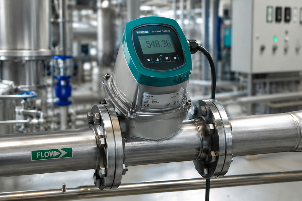
Electromagnetic flowmeters can provide considerably more information than the current volume flow alone. Depending on their design, modern electromagnetic flowmeters provide analogue current signals, pulse or frequency outputs, relay contacts and digital communication interfaces such as HART, Modbus, PROFIBUS or PROFINET.
However, these signals are not interchangeable. A 4–20 mA output is particularly suitable for transmitting the continuous instantaneous flow rate. A total quantity signal can often be transmitted more reliably using pulses or a digital totaliser. Relay outputs are intended for limit values and status messages, while fieldbus and Ethernet interfaces can transmit several process values, totaliser readings and diagnostic values simultaneously.
Before ordering, the measuring task, PLC inputs, required update rate, totalisers, diagnostic requirements and existing network technology must therefore be known. The electrical output type, scaling, fault response and whether an output is active, passive, potential-free or designed as an open collector are equally important.
Table of Contents
- Which values can an electromagnetic flowmeter output?
- Direct comparison of output signals
- 4–20 mA output for instantaneous flow rate
- 4–20 mA with HART
- Correctly distinguishing between pulse and frequency outputs
- Totalisers and quantity measurement
- Relay outputs for limit values and status
- Modbus RTU and Modbus TCP
- PROFINET for PLC and control-system integration
- Do not confuse PROFIBUS with PROFINET
- Correctly scaling the measuring range and output
- Representing bidirectional flow
- Fault signals and diagnostic information
- Active, passive and potential-free outputs
- Loop check and commissioning
- Typical wiring and parameterisation errors
- Practical example on a cooling-water line
- Selecting the output signal to suit the application
- Which measuring instruments / products are suitable?
- Conclusion
- Frequently asked questions
Which values can an electromagnetic flowmeter output?
An electromagnetic flowmeter first determines the average flow velocity of an electrically conductive liquid. The transmitter calculates the volume flow from the flow velocity and unobstructed pipe cross-section.
Depending on the instrument, this can be used to generate different process values and status information:
- current volume flow or instantaneous flow rate,
- flow velocity,
- forward, reverse and net quantity,
- totaliser or batch quantity,
- flow direction,
- limit and switching states,
- empty-pipe indication,
- electrode, conductivity or device information,
- warnings and fault codes.
The suitable output signal depends on which of these values is required by the controller. For continuous control, the instantaneous flow rate is typically transmitted. For filling or consumption accounting, by contrast, the quantity of liquid accumulated over a period of time is the primary value.
A single analogue output can transmit only one continuous measured value. A digital interface, by contrast, can provide several measured values, totalisers and diagnostic details simultaneously.
Direct comparison of output signals
| Output | Typical information | Strength | Important limitation |
|---|---|---|---|
| 4–20 mA | Instantaneous flow rate | Robust, straightforward and suitable for longer cable runs | Normally transmits only one scaled process value |
| 4–20 mA with HART | Instantaneous flow rate plus digital parameters and diagnostics | The existing analogue loop can continue to be used | Requires a suitable loop impedance and HART communication |
| Pulse output | Defined liquid quantity per pulse | Well suited to quantity counting and dosing | The pulse value and maximum frequency must be suitable |
| Frequency output | Frequency proportional to the instantaneous flow rate | Good digital resolution of the flow value | The PLC requires a suitable frequency or high-speed counter input |
| Relay output | Limit value, fault, flow direction or empty pipe | Simple, often potential-free switching contact | Not suitable for precise transmission of the flow value |
| Modbus RTU | Several process values, totalisers and diagnostic values | Efficient RS-485 communication with several devices | Registers, baud rate, address and data format must correspond |
| PROFIBUS | Cyclic process data and diagnostics | Widely used in many existing process plants | Not an Ethernet interface; the correct bus version is required |
| PROFINET | Cyclic process data, parameters and diagnostics | Direct integration into modern Ethernet-based PLC systems | Network planning, GSDML and device configuration are required |
Several outputs are often used in parallel. For example, the 4–20 mA output can transmit the instantaneous flow rate, the pulse output can count the total quantity and a relay output can indicate an empty-pipe condition or fault.
With full fieldbus or PROFINET integration, this information can often be transmitted through a single interface. Nevertheless, an additional analogue or relay output can be useful as an independent fallback signal.
4–20 mA output for instantaneous flow rate
The 4–20 mA output is widely used in industrial process measurement. The transmitter maps a configured flow range linearly to the current range.
A typical example is:
- 4 mA = 0 m³/h,
- 20 mA = 250 m³/h.
Intermediate values can be calculated using the following relationship:
Flow rate = lower flow value + (current − 4 mA) / 16 mA × measuring span
With scaling from 0 to 250 m³/h, 12 mA corresponds to exactly 125 m³/h.
Advantages of the current signal include:
- simple connection to analogue PLC inputs,
- low sensitivity to voltage drops along the cable,
- clear distinction between a cable break and a valid zero signal,
- standardised scaling,
- good suitability for control and monitoring tasks.
However, the current signal normally transmits only the instantaneous flow rate. If the PLC is to calculate a total quantity from it, the flow must be integrated over time. Sampling time, rounding, PLC downtime and changes to the scaling can introduce additional deviations.
For reliable quantity accounting, the internal electromagnetic-flowmeter totaliser or a separate pulse output is therefore often more suitable.
4–20 mA with HART
HART adds digital communication to the analogue 4–20 mA signal. The analogue current value remains available to the PLC or control system, while device parameters and additional information can be read digitally over the same loop.
Depending on the electromagnetic flowmeter, HART can provide information such as:
- current flow value,
- totaliser,
- measuring-range limits,
- damping and units,
- device identification,
- warnings and diagnostic information,
- output testing and parameterisation.
For stable HART communication, the current loop must have sufficient impedance. A resistor of approximately 250 Ω is used in many applications. However, the specifications of the transmitter, isolating power supply and HART communicator are decisive.
HART is particularly useful when an existing 4–20 mA infrastructure is to be retained but additional diagnostic and parameterisation functions are required.
Correctly distinguishing between pulse and frequency outputs
Although both signals may be provided by the same digital output, pulse and frequency modes perform different tasks.
Quantity-proportional pulse output
With a quantity-proportional pulse output, each output pulse represents a defined quantity of liquid, for example:
- 1 pulse per litre,
- 10 pulses per litre,
- 1 pulse per 10 litres,
- 1 pulse per cubic metre.
The total quantity is calculated as follows:
Total quantity = number of pulses × quantity per pulse
If 12,500 pulses are counted with scaling of 10 litres per pulse, the total quantity is 125,000 litres or 125 m³.
Flow-proportional frequency output
With a frequency output, the output frequency is proportional to the current flow rate. For example, 0 to 1,000 Hz may correspond to a flow range of 0 to 250 m³/h.
The PLC then measures not only the number of pulses but also the number of pulses per unit of time. This allows it to determine the instantaneous flow rate digitally.
The following limits must be checked before parameterisation:
- maximum output frequency of the electromagnetic flowmeter,
- maximum input frequency of the PLC,
- minimum pulse width,
- signal type, such as open collector, PNP, NPN or actively powered,
- required resolution at low flow rates.
Pulse scaling that is too fine may exceed the permissible frequency at high flow rates. Scaling that is too coarse, by contrast, results in long intervals between pulses and a sluggish indication at low flow rates.
Totalisers and quantity measurement
Many electromagnetic flowmeters maintain internal totalisers for forward, reverse and net flow. These totalisers are calculated directly from the internally determined flow value and, depending on the instrument design, remain available even if communication is interrupted.
There are three typical ways of transmitting the total quantity:
- pulse output to a PLC counter input,
- direct reading of the internal totaliser via Modbus, PROFIBUS or PROFINET,
- integration of the 4–20 mA instantaneous value in the PLC.
Directly reading an internal totaliser or evaluating quantity-proportional pulses is generally more reliable for consumption and batch measurements than integrating the analogue current signal alone.
When quantities are counted in the PLC, it must be defined how the following situations are handled:
- restart or replacement of the PLC,
- counter-register overflow,
- reverse flow,
- resetting the electromagnetic-flowmeter totaliser,
- communication failure,
- changes to the pulse value.
The pulse scaling should be documented and protected against unintended changes. If it is changed, for example, from “1 pulse per litre” to “1 pulse per 10 litres”, the PLC evaluation must also be adjusted.
Relay outputs for limit values and status
A relay output does not transmit a continuous measured value. It opens or closes a contact when a defined condition is met.
Typical functions include:
- minimum or maximum flow,
- flow inside or outside a window,
- flow direction,
- empty-pipe detection,
- device fault or common alarm,
- end of batch,
- totaliser limit value.
With a potential-free relay contact, the connected circuit can be operated independently of the electromagnetic flowmeter’s power supply. Nevertheless, the permissible contact voltage, contact current and load type must be observed.
Relay contacts are not generally suitable for rapid counting pulses. Mechanical wear and limited switching frequency mean that they are primarily suitable for status and limit-value messages. A dedicated electronic pulse output should be used for high-speed quantity counting.
The closed-circuit principle can be useful for reliable fault signalling. In this case, the relay is energised during fault-free operation. It drops out in the event of an instrument fault, power failure or cable break. Whether this function may be used as a safety-related signal depends on the complete installation and required approvals.
Modbus RTU and Modbus TCP
Modbus enables the digital transmission of several measured and diagnostic values. Modbus RTU and Modbus TCP must be distinguished from one another.
Modbus RTU
Modbus RTU typically operates over a serial RS-485 connection. Several instruments can be connected to one bus and queried sequentially by a master.
For successful communication, the following in particular must correspond:
- device address,
- baud rate,
- parity and stop bits,
- RS-485 A/B polarity,
- bus termination and cable routing,
- register addresses,
- data format and byte order.
Communication may be established successfully even though the PLC subsequently displays incorrect numerical values. This is often caused by incorrect interpretation of 16- or 32-bit registers, swapped words, an unaccounted scaling factor or unsuitable data-type conversion.
Modbus TCP
Modbus TCP uses Ethernet. Instruments are addressed using IP addresses. The logical register structure is similar to Modbus RTU, but the physical transmission and network planning differ fundamentally.
Modbus is particularly suitable when several measured values and totalisers are to be read without a complex manufacturer-specific bus structure. However, the PLC must actively poll the registers. The update time and bus load therefore depend on the polling cycle and number of devices.
PROFINET for PLC and control-system integration
PROFINET is an Ethernet-based communication solution for industrial automation. Unlike a simple register query, configured process data are exchanged cyclically between the electromagnetic flowmeter and controller.
Depending on the instrument, the following values may be transmitted:
- instantaneous flow rate,
- forward, reverse and net quantity,
- flow direction,
- device and process status,
- empty-pipe indication,
- warnings and diagnostic codes.
A GSDML file and device configuration in the engineering system are typically required for integration. The device name, IP address, data modules and scaling must correspond to the project configuration.
PROFINET provides advantages when:
- several process values are required simultaneously,
- rapid cyclic communication is required,
- advanced diagnostic information is to be evaluated,
- the plant already has a PROFINET infrastructure,
- device parameters are to be managed centrally.
An Ethernet socket alone does not automatically mean that the instrument supports PROFINET. EtherNet/IP, Modbus TCP, PROFINET and a web interface all use Ethernet as the transmission medium but are different protocols.
Do not confuse PROFIBUS with PROFINET
PROFIBUS is a serial fieldbus system, while PROFINET is based on Industrial Ethernet. An electromagnetic flowmeter with PROFIBUS PA or PROFIBUS DP therefore cannot be connected directly to a PROFINET port.
Typical differences include:
| Characteristic | PROFIBUS | PROFINET |
|---|---|---|
| Transmission | Serial fieldbus | Industrial Ethernet |
| Typical versions | PROFIBUS DP and PROFIBUS PA | PROFINET IO |
| Device description | GSD file | GSDML file |
| Addressing | Bus address | Device name and IP configuration |
| Typical application | Existing fieldbus and process plants | Modern PLC and Ethernet infrastructures |
During modernisation, it must be assessed whether existing PROFIBUS instruments are to remain in operation, be integrated through a gateway or be replaced with PROFINET-compatible transmitters.
Correctly scaling the measuring range and output
Unsuitable scaling can significantly reduce the usable resolution. If an electromagnetic flowmeter is scaled from 0 to 1,000 m³/h, for example, while actual operation is only between 0 and 100 m³/h, the 4–20 mA signal uses only a small part of its available span.
The normal operating flow should therefore use a sufficiently large proportion of the configured output range. At the same time, the maximum flow, possible peaks and overrange conditions must be considered.
The following must be documented:
- lower and upper flow value,
- assigned current or frequency values,
- flow unit,
- pulse value or K-factor,
- behaviour during reverse flow,
- underrange and overrange behaviour,
- alarm current or substitute value.
The PLC scaling must use exactly the same values. A typical source of error is that the electromagnetic flowmeter is configured for 0 to 250 m³/h while the analogue PLC input is still scaled from 0 to 200 m³/h.
Representing bidirectional flow
Many electromagnetic flowmeters can measure flow in both directions. The output must therefore be parameterised to suit the application.
Possible strategies include:
- 4 mA for maximum reverse flow, 12 mA for zero flow and 20 mA for maximum forward flow,
- 4 to 20 mA exclusively for the magnitude of the flow and a separate direction signal via relay or digital output,
- separate totalisers for forward and reverse quantity,
- transmission of a signed value via Modbus or PROFINET.
The available method depends on the transmitter. With an analogue signal, the PLC logic must be able to distinguish clearly whether a low current represents low forward flow or reverse flow.
Digital interfaces are often easier to use for bidirectional applications because a signed flow value, separate totalisers and status information can be transmitted.
Fault signals and diagnostic information
A valid zero-flow condition and an instrument fault must not appear identical in the controller. The output types provide different methods for distinguishing between them.
4–20 mA output
In the event of a fault, the transmitter may output a current outside the normal measuring range. Values below 4 mA or above 20 mA are frequently used. The specific values and the selection of a low or high alarm current depend on the instrument.
The PLC must explicitly evaluate the alarm range. If every current below 4 mA is simply interpreted as zero flow, a cable break or instrument fault may remain undetected.
Pulse output
If no pulses are received, this may indicate zero flow, a fault, a broken cable or missing power supply. An additional status output or digital diagnostic signal is therefore useful.
Relay output
A relay can be configured as a common alarm, empty-pipe indication or limit contact. The closed-circuit principle improves the detection of power failures and cable breaks.
Digital communication
Modbus, PROFIBUS and PROFINET can transmit additional status bits and diagnostic codes alongside the measured value. However, the control software must actively evaluate this information. A displayed numerical value is not automatically valid if a poor device status is transmitted at the same time.
Active, passive and potential-free outputs
The signal designation alone does not describe the electrical circuit. Two electromagnetic flowmeters with a 4–20 mA output may require different wiring.
Active current output
An active output provides the loop current using the electromagnetic flowmeter’s own power supply. The PLC requires a passive analogue input. The maximum permissible load resistance of the output must be observed.
Passive current output
A passive output requires an external loop supply. The circuit consists of the power supply, electromagnetic-flowmeter output, analogue input and cable resistance.
Open-collector or transistor output
A passive pulse output often switches only an electronic transistor. An external supply and suitable input circuit are required to produce a complete voltage signal. PNP, NPN, push-pull, maximum voltage and switching current must be checked.
Relay contact
A genuine relay contact is often potential-free. It does not require a common ground with the PLC but has a limited contact rating and switching frequency.
The electrical wiring diagram, rather than only the output designation, must therefore be checked before connection.
Loop check and commissioning
During commissioning, the sensor, transmitter, wiring and PLC evaluation should be tested separately. A plausible flow value on the display does not prove that the output is reaching the controller correctly.
Testing the 4–20 mA output
- Document the scaling configured in the electromagnetic flowmeter.
- Check the output type and permissible load resistance.
- Measure the current signal in series.
- Use the electromagnetic flowmeter’s internal output test where available.
- Check the PLC indication at 4, 8, 12, 16 and 20 mA.
- Test the underrange, overrange and alarm current.
To test the analogue PLC input, the electromagnetic-flowmeter output can be disconnected and a Druck UPS4E current-loop calibrator connected. The UPS4E generates defined current values and therefore enables testing independently of the flowmeter.
With an electromagnetic flowmeter, the 4–20 mA output is normally linear to the volume flow. Linear current steps should therefore be used for the loop check. A square-root characteristic is only correct if it is explicitly intended for the respective measuring circuit.
A current calibrator must not be connected in parallel with an active current output without checking the circuit. For simulation, the electromagnetic-flowmeter output is disconnected from the loop and replaced by the calibrator.
Testing the pulse output
An internal output test or a controlled flow can be used to test the pulse output. The pulse value, signal level, pulse width and PLC counter reading must be compared.
Testing Modbus or PROFINET
With digital interfaces, the communication, device status, data format and update time must be checked in addition to the numerical value. A current-loop calibrator cannot simulate this bus communication.
Typical wiring and parameterisation errors
Instantaneous flow and total quantity are confused
The 4–20 mA output provides the current flow rate while the PLC expects a total quantity. A totaliser cannot be produced without integration over time.
The pulse value is interpreted incorrectly in the PLC
The electromagnetic flowmeter outputs, for example, one pulse per ten litres, while the PLC calculates using one pulse per litre. The totaliser therefore differs by a factor of ten.
A standard digital input is used for high-speed pulses
The input filtering or PLC cycle time is too slow. Individual pulses are not detected.
Active and passive outputs are combined incorrectly
A passive current output receives no loop voltage, or two active sources are connected against one another.
An open-collector output is treated like a relay
The required supply or load circuit is missing. No defined signal is produced at the PLC input.
An alarm current is interpreted as a process value
A current below 4 mA, for example, is limited to zero flow in the PLC even though the electromagnetic flowmeter is reporting a fault.
Modbus data words are swapped
Communication operates, but the floating-point value is interpreted using the wrong byte or word order.
PROFINET and EtherNet/IP are treated as identical
Both use Ethernet but require different device options and configuration files.
A PROFIBUS instrument is connected to PROFINET
The mechanical or electrical interface and communication protocol are not compatible.
The scaling is changed only in the electromagnetic flowmeter
After the full-scale value is changed, the old scaling remains in the PLC. The display and control system show different flow values.
Practical example: Connecting an electromagnetic flowmeter to a cooling-water line
In a production plant, the cooling-water flow of a machine is to be monitored while the consumed water quantity is recorded. The normal flow is between 25 and 120 m³/h. The electromagnetic flowmeter is configured for 0 to 150 m³/h.
The controller requires three pieces of information:
- instantaneous flow rate for the process display,
- total quantity for consumption analysis,
- fault message for an empty pipe or instrument fault.
The 4–20 mA output is scaled from 0 to 150 m³/h and connected to an analogue PLC input. At 12 mA, the PLC must therefore indicate 75 m³/h.
The digital output is parameterised as a quantity-proportional pulse output. One pulse corresponds to 100 litres. The PLC counts the pulses using a high-speed counter input and calculates the total quantity.
The relay is configured as a common alarm according to the closed-circuit principle. During fault-free operation, the contact is energised. It drops out in the event of an empty pipe, instrument fault or power failure.
During commissioning, the electromagnetic-flowmeter display indicates 75 m³/h, while the PLC shows only 60 m³/h. The measured current is correctly 12 mA. The analogue input in the PLC is still scaled to a full-scale value of 120 m³/h. After correcting it to 150 m³/h, the values correspond.
During testing of the quantity counter, it is also found that the PLC evaluates every pulse as one litre. After adjusting it to 100 litres per pulse, the PLC totaliser also corresponds to the internal electromagnetic-flowmeter totaliser.
In a modernised version of the installation, the instantaneous flow rate, totaliser and diagnostic status could alternatively be transmitted together via PROFINET. Whether additional analogue or relay outputs continue to be used depends on the required redundancy.
Selecting the output signal to suit the application
At least the following questions should be answered during selection:
- Is the instantaneous flow rate, total quantity or both required?
- Is the flow to be controlled or only monitored?
- Which analogue and digital inputs are available on the PLC?
- Is a high-speed counter input available?
- Which bus or Ethernet infrastructure is already in use?
- Are diagnostic and device-status values required?
- Must the electromagnetic flowmeter provide an independent signal if communication fails?
- Must bidirectional flow be measured?
- Which update time is required?
- Should the totaliser continue operating while the PLC is switched off?
- Which electrical output type is required?
- Which fault response must the controller detect?
| Requirement | Generally suitable solution |
|---|---|
| Simple instantaneous flow rate to the PLC | 4–20 mA |
| Instantaneous flow plus parameterisation and diagnostics | 4–20 mA with HART |
| Consumption or quantity counting | Quantity-proportional pulse output or digital totaliser |
| Digital instantaneous flow using a counter input | Frequency output |
| Limit value, empty pipe or common alarm | Relay or status output |
| Several instruments on one RS-485 line | Modbus RTU |
| Existing PROFIBUS process plant | PROFIBUS DP or PA to suit the infrastructure |
| Modern Ethernet-based PLC integration | PROFINET |
| Several process values and comprehensive diagnostics | Digital fieldbus or Ethernet interface |
| Independent fallback signal in addition to the bus | PROFINET or Modbus plus 4–20 mA or relay |
Which measuring instruments / products are suitable?
Electromagnetic flowmeters
The electromagnetic flowmeters category includes compact and remote systems for conductive liquids.
Depending on the model, 4–20 mA/HART outputs, pulse and frequency outputs, relay contacts, Modbus, PROFIBUS, PROFINET, EtherNet/IP or IO-Link are available. The output type and communication module must be selected to suit the controller.
SITRANS FMT020
The SITRANS FMT020 is a modern electromagnetic-flowmeter transmitter for volume flow, flow velocity and electrical conductivity.
It features one current output, one digital output and one relay output. Depending on the version, HART, PROFINET, EtherNet/IP and Modbus RTU are available for digital communication.
The FMT020 is therefore suitable both for conventional PLC connections using 4–20 mA, pulse and relay signals and for modern Ethernet and fieldbus integration. The required communication version must be specified when ordering.
SITRANS MAG 5000 and MAG 6000
The SITRANS MAG 5000 / MAG 6000 transmitters provide analogue, pulse/frequency and relay outputs in their standard configuration.
The MAG 6000 additionally supports optional communication modules for HART, FOUNDATION Fieldbus, DeviceNet, Modbus RTU/RS-485 and PROFIBUS PA and DP.
These instruments are particularly relevant for existing SITRANS FM measuring points and installations in which conventional output signals or established fieldbus systems are to remain in use.
INDUQ-VMI20
The INDUQ-VMI20 is a compact electromagnetic flow sensor for water and other conductive liquids.
It has a configurable pulse output. A 4–20 mA output is optionally available. This makes the instrument suitable for compact machinery and plant applications requiring either a quantity pulse sequence or an analogue instantaneous-flow signal.
Druck UPS4E for 4–20 mA loop checks
The Druck UPS4E current-loop calibrator can measure and generate current signals from 0 to 24 mA.
During commissioning of an electromagnetic flowmeter, it can be used to check the 4–20 mA output or test the analogue PLC input independently of the flowmeter using defined current values. It also provides an internal 24 V loop supply, linear step sequences and an integrated 250 Ω resistor for HART applications.
The UPS4E tests only the analogue current loop. Other testing and engineering tools are required for pulse, Modbus, PROFIBUS or PROFINET interfaces.
Conclusion: The output signal must suit the measuring task and PLC
The 4–20 mA output is a robust solution for transmitting the continuous instantaneous flow rate. For reliable measurement of the total quantity, a quantity-proportional pulse output or digitally read electromagnetic-flowmeter totaliser is often more suitable.
Relay outputs transmit limit values, empty-pipe indications or instrument faults but are not intended for precise flow transmission. Pulse and frequency outputs must be carefully configured with regard to pulse value, maximum frequency, signal level and PLC input.
Modbus enables comparatively simple digital transmission of several registers. PROFINET provides deep integration into modern PLC and Ethernet structures with cyclic process data and advanced diagnostic capabilities. PROFIBUS and PROFINET are technically different systems.
Regardless of the signal type, the scaling, flow direction, fault response and electrical output type must be clearly documented. Many apparent measuring errors do not originate in the electromagnetic flowmeter but result from different scaling, unsuitable inputs or incorrectly interpreted data formats.
At important measuring points, a combination can be useful: digital communication for process values and diagnostics, an independent 4–20 mA output for the instantaneous flow rate and a relay contact for the common alarm.
Frequently asked questions about electromagnetic-flowmeter output signals
Which electromagnetic-flowmeter output is suitable for the instantaneous flow rate?
The 4–20 mA output is particularly suitable for a straightforward PLC connection. Alternatively, the instantaneous flow rate can be transmitted using a frequency output or a digital interface such as Modbus or PROFINET.
Can the total quantity be transmitted via 4–20 mA?
A 4–20 mA signal normally represents the current flow rate. The PLC can integrate this value to calculate a quantity, but a pulse output or direct digital access to the internal totaliser is often more reliable.
What is the difference between a pulse output and a frequency output?
With a quantity signal, each pulse represents a defined liquid quantity. With a frequency output, the number of pulses per second is proportional to the current flow rate.
Can a standard PLC digital input count pulses?
Only if the input filtering and PLC cycle time are sufficient for the maximum pulse frequency. High-speed signals require a high-speed or counter input.
What is the relay output of an electromagnetic flowmeter used for?
Typical applications include limit values, empty-pipe indication, flow direction, end of batch or common alarm. A relay is not suitable for continuous transmission of the flow value.
What advantages does HART offer compared with a standard 4–20 mA output?
The analogue flow value remains available. Device parameters, additional process values and diagnostic information can also be transmitted digitally.
What is the difference between Modbus RTU and PROFINET?
Modbus RTU typically operates as a serial RS-485 system using register queries. PROFINET is Ethernet-based and cyclically exchanges configured process data between the instrument and PLC.
Is PROFINET the same as PROFIBUS?
No. PROFIBUS is a serial fieldbus. PROFINET is based on Industrial Ethernet and requires different device options, cables and configuration files.
How do I test the 4–20 mA output of an electromagnetic flowmeter?
The current can be measured in series using a suitable multimeter or current-loop calibrator. To test the PLC input, the electromagnetic-flowmeter output is disconnected and replaced by a defined mA source such as the Druck UPS4E.
Which information does ICS Schneider require for selection?
The required information includes the medium, conductivity, nominal pipe size, flow range, required instantaneous and total values, PLC inputs, output signal, pulse value, communication protocol, fault response, power supply, electrical output type and requirements for diagnostics, redundancy and Ex approval.