


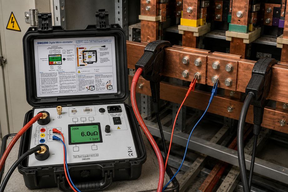
During maintenance of a switchgear system, the contact resistance of a bolted copper busbar connection is tested. The micro-ohmmeter initially indicates 8.4 µΩ. After one of the test clamps is repositioned, the measured value suddenly drops to only 5.9 µΩ. A further measurement a few minutes later shows 6.3 µΩ. Has the resistance of the connection actually changed, or is the test setup influencing the result?
Especially in the micro-ohm range, small differences in contact placement can have a major influence. The voltage drops evaluated by the measuring instrument are often only in the microvolt range. Contact resistances of the current connections, incorrectly positioned sense leads, different contact points and thermoelectric voltages can therefore cause changes in the measured value that are in the same order of magnitude as the actual resistance of the busbar connection.
Four-wire or Kelvin measurement solves an important part of this problem by separating current flow from voltage measurement. However, it only works reliably if the four contacts are positioned correctly. The two current contacts must drive the test current through the section being investigated, while the two sense contacts measure the voltage drop immediately before and after the actual connection.
For micro-ohm measurements on busbars, the accuracy of the measuring instrument alone therefore does not determine the quality of the result. Contact position, test current, thermoelectric voltages, temperature and a reproducible test procedure are at least equally important.
Why are a few micro-ohms relevant on busbars?
A busbar connection is intended to carry very high currents with as little voltage drop as possible. The resistance of an intact connection is therefore extremely low. This is precisely why changes in the micro-ohm range become significant. Corrosion, oxide layers, insufficient tightening torque, contaminated contact surfaces or mechanically damaged connections can increase the contact resistance.
The thermal significance of such a change can be estimated from the power loss using P = I² × R. At an operating current of 2,000 A, an additional resistance of only 10 µΩ already produces a power loss of 40 W. This power is generated locally at the connection and can cause significant heating.
Nevertheless, an absolute resistance value should not be assessed in isolation. Design, material, cross-section, length of the measured section, temperature and type of connection all influence the expected value. Comparison measurements between identical phases or repeated trend measurements on the same connection are therefore particularly informative.
Why is four-wire technology necessary?
In a conventional two-wire resistance measurement, the same leads carry the measuring current and measure the voltage drop. As a result, the resistance of the test leads and the contact resistance of the test connections are included directly in the result. With resistances of only a few micro-ohms, these additional contributions would often be larger than the resistance actually being measured.
Four-wire technology therefore separates the current path from the voltage-measuring path. Two heavy-duty leads, often referred to as Current or Force, carry a defined test current through the busbar. Two additional high-impedance sense leads measure only the voltage between two precisely defined points. Practically no relevant current flows through the sense leads, so their own lead and contact resistances have almost no influence on the measured voltage drop.
The resistance is then calculated from the test current and sense voltage:
R = U / I
For example, with a test current of 200 A and a measured voltage drop of 1.2 mV, the resulting resistance is 6 µΩ.
Correctly positioning force and sense contacts
The most important geometric rule is that the two sense contacts must be located inside the two current contacts. Only then is the voltage drop measured precisely across the section that is to be evaluated. For a bolted overlapping busbar connection, the current clamps are therefore placed outside the connection, while the two potential contacts are positioned immediately before and after the overlap area.
| Contact | Function | Typical position |
|---|---|---|
| Current / Force + | Feeds the test current into the test object | Outside the connection being evaluated |
| Sense + | Measures the voltage immediately before the contact point | Inside the current contact |
| Sense − | Measures the voltage immediately after the contact point | Inside the opposite current contact |
| Current / Force − | Returns the test current to the measuring instrument | Outside the second sense contact |
Even a difference of only a few centimeters in the position of the sense contacts changes the length of conductor included in the measurement. If, for example, a longer section of copper busbar is included during a repeat test than during the original measurement, the resistance may appear higher even though the actual bolted connection has not changed at all.
Why contact surfaces influence the result
The current clamps must safely carry a high test current. Oxidized, painted or heavily contaminated surfaces can impair the current contact. With correct four-wire measurement, this does not directly mean that the contact resistance of the current clamp is included in the measured result, but the instrument must still be able to drive the specified test current through the test object.
The sense contacts must also make reliable contact. Because the current through them is extremely small, current-carrying capacity is less important than a reproducible electrical connection. Contacting dirt, paint, heavy oxide layers or loose surfaces can result in unstable microvolt readings.
Contact surfaces should therefore be in a defined condition before comparison measurements are performed. However, the cleaning process itself must not alter the connection being evaluated. In particular, the actual contact surface of a bolted busbar connection should not be loosened or reworked solely for the measurement if its existing condition is precisely what is to be assessed.
Which test current is appropriate?
A higher test current produces a larger measurable voltage drop for the same resistance. At 1 µΩ, a current of 10 A produces only 10 µV, whereas 200 A produces 200 µV. This can significantly improve the ratio between the useful signal and small interference voltages.
However, the highest available test current is not automatically the best choice. The manufacturer’s specifications for the test object, thermal capacity, test duration and comparability with previous measurements must be considered. If a trend measurement is performed once at 50 A and at the next maintenance interval at 200 A, differences may arise from temperature and contact behavior even though the electrical connection itself has not changed significantly.
| Influence of test current | At low test current | At higher test current |
|---|---|---|
| Voltage drop across test object | Smaller | Larger and easier to measure |
| Influence of small interference voltages | Relatively greater | Relatively lower |
| Self-heating | Lower | Can increase during long test durations |
| Requirements for current contacts | Lower | Very good contact required |
| Comparability | Keep the test current as consistent as possible for repeated measurements | |
Recognizing thermoelectric voltages in the microvolt range
A special characteristic of micro-ohm measurements is that not every measured voltage is caused by the test current. When different metals come into contact and temperature differences exist between the contact points, thermoelectric voltages can occur. These are often only in the microvolt range – exactly where the useful signal of a micro-ohm measurement may also lie.
Assume that a busbar connection has a resistance of 1 µΩ. At a test current of 100 A, the actual voltage drop is only 100 µV. An additional thermoelectric voltage of 5 µV would already correspond to five percent of the useful signal in this example.
Thermoelectric voltages can occur in particular when the switchgear has only recently been under load, individual busbars are still warm, test contacts are at different temperatures or different metals meet at the connection points. A reproducible micro-ohm test should therefore be carried out under thermally stable conditions whenever possible.
How does current reversal help?
An effective method of reducing constant thermoelectric voltages is to measure with two current directions. When the test current is reversed, the voltage drop caused by electrical resistance changes its polarity. A constant thermoelectric voltage, however, initially remains in the same direction.
In simplified form:
U+ = R × I + Uthermo
and with reversed current direction:
U− = −R × I + Uthermo
The resistance component can then be determined from both measurements:
R = (U+ − U−) / (2 × I)
This mathematically suppresses a thermoelectric voltage that remains largely constant during both measurements. The prerequisite is that temperature and contact conditions do not change significantly between the two measurements. Whether and how such offset compensation or current reversal is performed depends on the micro-ohmmeter being used.
Taking busbar temperature into account
The actual electrical resistance of the busbar also depends on temperature. Copper has a positive temperature coefficient. A warm busbar therefore has a higher resistance than the same connection at a lower temperature. If maintenance measurements are compared without taking temperature into account, this can incorrectly suggest deterioration of the connection.
For copper around room temperature, a temperature coefficient of approximately 0.00393/K can be used as an approximation. A temperature change of 20 K therefore changes the conductor resistance by several percent. For precise comparison measurements, tests should either be carried out at comparable temperatures or the resistance should be converted to a defined reference temperature using an established procedure.
The test current itself can also heat the measuring point. If the resistance rises continuously during a prolonged high-current test, it is therefore necessary to distinguish between unstable contact placement and an actual temperature increase in the test object.
Why comparison and trend measurements are particularly valuable
There is not always a universal limit value for busbar connections that can be applied independently of design and measurement conditions. A resistance of, for example, 8 µΩ may be perfectly acceptable for one design but clearly too high for another. Measurements on comparable connections within the same system are therefore particularly valuable.
For a three-phase busbar system, for example, the contact resistances of three identical phase connections can be compared. If two connections measure approximately 5.1 µΩ and 5.3 µΩ, while the third measures 11.8 µΩ, the third connection is clearly suspicious even if no general limit value is available.
An initial measurement documented after assembly or commissioning is even more informative. If the same connection is later measured again using the same contact positions, the same test current and a comparable temperature, gradual deterioration can be detected much more reliably.
Practical example: suspicious bolted busbar connection
During a maintenance test, three identical copper busbar connections are examined using a test current of 200 A. The first two phases measure 5.4 µΩ and 5.6 µΩ. On the third phase, the micro-ohmmeter initially indicates 9.7 µΩ. The connection therefore appears suspicious.
Before making a technical assessment, however, the measurement is repeated completely. It is found that the sense contact on the third phase was positioned significantly farther away from the bolted connection than on the other two phases. After identical positioning immediately before and after the overlap joint, the measured resistance is 6.0 µΩ.
A further measurement a few minutes later gives 6.1 µΩ. The busbar had previously still been slightly warm and was stabilizing during the test. The connection is therefore much closer to the other two comparison phases than the initial measurement suggested.
This example shows why a single micro-ohm value has only limited significance without reproducible contact positioning and known temperature conditions. Only a controlled comparison turns the numerical value into a reliable diagnostic result.
Systematic test procedure
- De-energize the system in accordance with the applicable safety rules and secure it against reconnection.
- Clearly define the section to be tested: Between which points before and after the connection should the voltage drop be measured?
- Position the current contacts outside the measuring section: They must be capable of reliably carrying the intended test current.
- Position the sense contacts inside the current contacts: Ideally immediately before and after the connection being evaluated.
- Define and document the test current: Use the same value wherever possible for repeat measurements.
- Document the busbar temperature or ambient conditions.
- Repeat the measurement several times: Check stability and repeatability.
- If thermoelectric voltages are relevant, use offset compensation or current reversal.
- Compare the result with identical connections and previous measurements.
Common measurement errors
- Positioning sense contacts outside the current clamps: This includes additional conductor and contact sections in the voltage measurement.
- Changing contact positions between measurements: Even a few additional centimeters of busbar can distort the comparison.
- Poor current contact: The specified test current may not be reached reliably.
- Ignoring thermoelectric voltages: With microvolt-level signals, thermoelectric voltages can create a significant measurement error.
- Directly comparing warm and cold busbars: The electrical resistance of copper changes with temperature.
- Using different test currents for trend measurements: Heating and contact behavior may then differ between measurements.
- Assessing an isolated absolute value without comparison: Design and geometry strongly influence which resistance is plausible for a particular connection.
Micro-ohmmeters for busbars
For resistance measurements on massive busbars and high-current connections, a micro-ohmmeter with four-wire technology and a sufficiently high test current is suitable. One example is the DMO200K Digital Micro-Ohmmeter. The instrument generates an adjustable DC test current of 1 ... 200 A and offers a resolution down to 0.1 µΩ.
The DMO200K is supplied with a Kelvin clamp set and a 3 m output cable set. This allows current and potential contacts to be separated specifically when testing busbars, cable lugs and switch contacts. Test current, measured voltage and resistance are displayed simultaneously, making it possible to verify whether the specified test current has actually been reached.
For other applications, micro-ohmmeters with lower test currents and additional high-current systems are also available. The expected resistance range, test object, required test current, desired resolution and necessary connection accessories are decisive when selecting the instrument.
Suitable instruments can be found under electrical measuring and test equipment at ICS Schneider and specifically under resistance measuring instruments / micro-ohmmeters.
Conclusion
Four-wire technology is the basis for reliable micro-ohm measurements on busbars because it separates current flow from voltage measurement. This largely removes the resistance of the current leads and current contacts from the actual measurement result.
However, the method does not automatically eliminate every measurement error. Correct geometric contact placement is particularly important: the sense points must be located inside the current contacts and positioned reproducibly immediately before and after the connection being tested. Different measuring positions inevitably mean that different conductor sections are being evaluated.
At resistances in the micro-ohm range, thermoelectric voltages and temperature also play a major role. Current reversal or offset compensation can reduce the influence of largely constant thermoelectric voltages. For comparison measurements, test current, temperature and contact position should also be documented.
For reliable busbar measurements, the following therefore applies: connect the four-wire system correctly, define the sense contact points precisely, use a suitable and reproducible test current, take thermoelectric voltages and temperature into account, and preferably compare the measured value with identical connections or documented previous measurements.
FAQ: Micro-ohm measurement on busbars
Why is four-wire measurement used for busbars?
At resistances in the micro-ohm range, the resistance of test leads and current contacts would be far too large in a two-wire measurement. Four-wire technology separates the test current from the voltage measurement and enables targeted determination of the resistance of the actual connection.
Where must the sense contacts be positioned in a Kelvin measurement?
The sense contacts must be positioned inside the two current contacts. On a bolted busbar connection, they should ideally be located immediately before and after the connection being evaluated.
Why does the measured value change when the Kelvin clamps are repositioned?
Changing the position of the sense contacts changes the length of conductor over which the voltage drop is measured. A different total resistance is therefore included in the measurement.
Why are high test currents used for busbars?
A higher test current produces a larger voltage drop for the same small resistance. This increases the useful signal relative to small interference and thermoelectric voltages. However, the test current must be suitable for the test object and the intended test method.
What are thermoelectric voltages in a micro-ohm measurement?
Thermoelectric voltages can arise at junctions between different metals when temperature differences are present. They are often only in the microvolt range, but in micro-ohm measurements they can already represent a significant proportion of the measured signal.
How can thermoelectric voltages be compensated?
One method is to measure using both current directions. The resistance-related voltage drop changes polarity, while a largely constant thermoelectric voltage remains unchanged. The resistance component can then be calculated from the two measurements.
Does temperature influence the resistance of a copper busbar?
Yes. Copper has a positive temperature coefficient. A warm busbar therefore has a higher electrical resistance than the same connection at a lower temperature.
Can a fixed maximum permissible micro-ohm value be specified for busbars?
Not generally. The expected resistance depends on factors such as material, geometry, length and type of connection. Comparisons with identical connections and documented baseline measurements are particularly meaningful.
Why are trend measurements useful for busbars?
If the same connection is measured regularly under comparable conditions, a gradual increase in contact resistance can be identified much more reliably than from a single absolute measurement.
Which specific measuring instrument is suitable for micro-ohm measurements on busbars?
For massive busbars and high-current connections, the DMO200K Digital Micro-Ohmmeter is one suitable option. It uses Kelvin four-wire technology, provides test currents up to 200 A and offers a resolution down to 0.1 µΩ.