


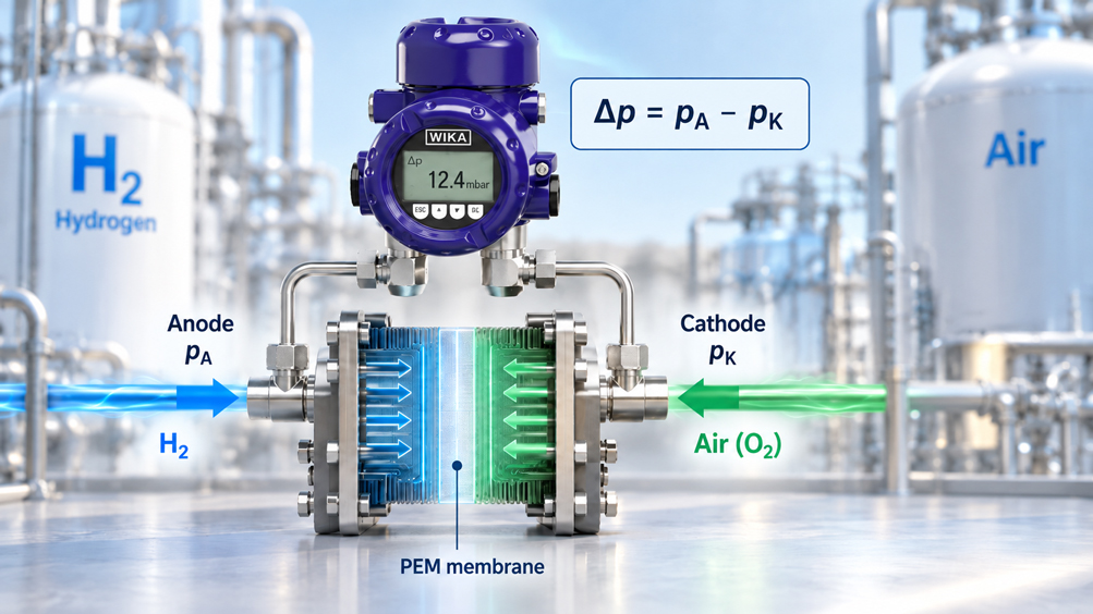
In a PEM fuel cell, two completely different gas spaces are located on opposite sides of a very thin polymer membrane. Hydrogen-containing fuel gas flows on the anode side, while air is normally used on the cathode side, or oxygen-enriched gas in certain test benches. The membrane must transport protons while at the same time separating the two reaction gases as reliably as possible.
For the service life of the membrane, it is therefore not only important which absolute pressure is present on the anode or cathode side. The pressure difference between both sides is also decisive. If the pressure on one side rises significantly faster or higher than on the other, a mechanical load is applied across the membrane electrode assembly.
This situation does not occur only because of an incorrectly adjusted static pressure regulator. Critical differential-pressure peaks can occur during system start-up and shutdown, rapid load changes, start-up of the air compressor, hydrogen purge events, valve switching or changes in recirculation. A measuring point that appears completely unremarkable during steady-state operation can therefore experience a significantly higher differential pressure during a transient event.
A reliable protection concept must therefore consider both static differential pressure and pressure dynamics.
There is another important factor: Pressure is not the same at every point in the stack. On both the anode and cathode sides, pressure decreases along the flow channels. A differential pressure measured at the inlet therefore does not automatically represent the highest local pressure difference that occurs anywhere across the active membrane area.
The key point is: Protecting a PEM fuel cell membrane requires more than two plausible pressure readings. Anode and cathode pressures must be time-aligned, differential pressure must be measured with sufficient accuracy and dynamic response, and the measuring position must reflect the actual pressure distribution within the stack. The permissible limit is not universally defined, but must be specified by the respective stack or MEA manufacturer.
Table of Contents
- Why the PEM membrane is sensitive to differential pressure
- Clearly define differential pressure
- Why there is no universal differential-pressure limit
- Why dynamic pressure peaks are particularly critical
- Why the measuring position on the stack is decisive
- Measure differential pressure directly or use two individual pressure measurements?
- Design differential-pressure and static-pressure ranges separately
- Why two accurate pressure sensors can still produce a poor Δp value
- Consider impulse lines, dead volume and condensate
- Select suitable materials for the hydrogen side
- Consider the air and oxygen side separately
- Keep anode and cathode media safely separated
- Use differential pressure for control and protection
- Do not confuse electronic damping with mechanical protection
- Check zero point and measurement chain correctly
- Systematically diagnose typical fault patterns
- Special considerations for fuel cell test benches
- Select the correct measuring instrument
- Suitable pressure measurement technology from ICS Schneider
- Conclusion
- Frequently asked questions about differential-pressure measurement on PEM fuel cells
1. Why the PEM membrane is sensitive to differential pressure
The proton exchange membrane of a PEM fuel cell is part of the membrane electrode assembly and is surrounded on both sides by catalyst layers, gas diffusion layers and flow fields. During operation, the membrane is therefore exposed not only to chemical and thermal loads, but also to mechanical forces.
One important source of mechanical load is the pressure difference between the anode and cathode sides. If both sides are exposed to approximately the same pressure, the pressure forces acting over the surface largely cancel each other out. If the gas pressure on one side rises relative to the other, an additional resultant force acts across the membrane electrode assembly.
This pressure load does not act in isolation. At the same time, the membrane changes depending on temperature and water content. During humidification and drying, the polymer swells or shrinks while being mechanically constrained within the stack. Differential pressure, humidity cycles, temperature cycles and mechanical clamping can therefore interact with one another.
A permanently or repeatedly excessive pressure difference can contribute to additional deformation and generate mechanical stress peaks, particularly at transition zones, edges and sealing areas. Over the long term, this increases the risk of material fatigue, local defects or cracking.
If a relevant membrane defect eventually occurs, not only electrical performance is affected. Hydrogen and oxidant gas can then cross between the anode and cathode sides. Membrane protection is therefore simultaneously a matter of service life, functionality and system safety.
2. Clearly define differential pressure
Before limits or control algorithms are defined, the sign convention should be specified unambiguously.
For this article, the following definition is used:
Δp = pAnode − pCathode
A positive value therefore means that the pressure on the anode side is higher. A negative value means that the cathode pressure is higher.
This apparently simple definition is important in practice. If sensors, PLCs and test-bench software use different sign conventions, an acceptable positive offset can appear as a negative limit in another evaluation system.
During commissioning, it is therefore not sufficient to check only one numerical value. The response to a controlled change in anode or cathode pressure must also correspond to the expected sign.
For systems in which both pressure directions can occur, a bidirectional differential-pressure range around zero is often more useful than an exclusively positive measuring range. This immediately reveals when the side that normally operates at higher pressure temporarily falls below the pressure of the opposite side.
3. Why there is no universal differential-pressure limit
For PEM fuel cells, no single value such as “maximum 100 mbar” or “maximum 200 mbar” can be applied universally to every membrane and every stack.
The permissible differential pressure depends, among other factors, on membrane type and thickness, membrane reinforcement, MEA design, active area, sealing concept, support structure, temperature, humidity and the operating condition of the stack.
The duration of the load is also relevant. A short transient and a pressure difference applied for several hours do not necessarily create the same mechanical stress.
For this reason, technical literature contains different concrete values for different membranes and cell configurations investigated. These values are useful for understanding the mechanical relationships, but they must not be treated as universal operating limits.
For a real system, the permissible steady-state differential pressure, any short-term limits and the permissible rate of pressure change must be derived from the specifications of the stack or MEA manufacturer.
This is particularly important for test benches. A test bench used with different stacks may require different alarm and shutdown limits even when the same pressure measurement technology is used.
4. Why dynamic pressure peaks are particularly critical
During steady-state operation, anode and cathode pressure can be balanced comparatively easily. The situation becomes more difficult during dynamic changes.
On the cathode side, for example, pressure dynamics are determined by the air path with compressor, throttle or backpressure control, humidification and flow resistance. On the anode side, pressure-control valves, injector, ejector or recirculation pump, purge valve and water separation all influence pressure behavior.
These components have different response times.
During a rapid load step, one side may therefore already have reached a new pressure state while the other side is still adjusting. It is precisely during this transition that a temporary differential pressure occurs.
Particular attention should be paid to start-up, shutdown and purge events. If, for example, the hydrogen path is rapidly depressurized while cathode pressure is still present, the sign of Δp can temporarily reverse. Conversely, a rapidly opening hydrogen valve can cause a positive pressure spike before the cathode side has responded.
For membrane protection, therefore, not only the accuracy of a sensor at a stable test point is important. Response time, acquisition sampling rate, controller cycle time and the response speed of the pressure-control system are equally decisive.
5. Why the measuring position on the stack is decisive
The anode and cathode each have their own pressure drop between inlet and outlet.
For example, anode pressure can decrease from the hydrogen inlet toward the recirculation or exhaust section. At the same time, cathode pressure also decreases across channels, gas diffusion layers and the outlet path.
As a result, the local anode-to-cathode differential pressure is not necessarily constant across the active stack length.
A differential-pressure sensor that compares only anode and cathode inlet pressure therefore initially monitors only these two process points. It does not automatically indicate the local Δp value at the opposite end of the stack.
If a known and stable pressure-drop model is available, the critical local differential pressure can be estimated from the existing measurements. For development and validation test benches, however, more extensive pressure instrumentation is often useful.
Depending on the stack concept, anode and cathode inlet, outlet or additional reference points can be measured. The measuring position used for a protection function must therefore be defined together with the stack manufacturer and the pressure-drop characteristics of the system.
6. Measure differential pressure directly or use two individual pressure measurements?
Two fundamental measurement concepts are available for determining anode-to-cathode differential pressure.
With direct differential-pressure measurement, the anode and cathode pressures are connected to the two process connections of a common differential-pressure transmitter. The measuring cell responds directly to the pressure difference.
Alternatively, each side can be measured with its own pressure sensor. The differential pressure is then calculated in the controller from the two signals.
| Measurement concept | Advantage | Particularly important |
|---|---|---|
| Direct differential-pressure transmitter | A small Δp span can be measured directly with high resolution | Both process media are present at the same instrument; media compatibility, separation and failure behavior must be assessed |
| Two separate pressure sensors | Hydrogen and cathode sides remain physically separated in the measurement system | Measurement errors of both sensors affect the calculated differential pressure |
| Two high-accuracy, synchronously acquired sensors | Both individual absolute/system pressures are also available separately | High requirements for accuracy, temperature behavior, synchronization and calibration |
Which principle is more suitable depends strongly on the application.
If, for example, only a few tens of millibars of differential pressure must be detected reliably at an operating pressure of several bar, a true differential-pressure measuring cell has a clear metrological advantage.
On a development test bench, however, two highly accurate and fast individual channels may be useful because the complete dynamics of both gas-supply systems are also to be analyzed.
7. Design differential-pressure and static-pressure ranges separately
One of the most common selection errors with differential-pressure sensors is to consider only the Δp measuring range.
A sensor may, for example, have a measuring range of −100…+100 mbar while simultaneously being exposed to a much higher absolute or static pressure on both process sides.
This so-called common-mode or static pressure must be safely tolerated by the measuring cell.
The possible unilateral overload must also be considered. During normal operation, the anode and cathode may operate at almost the same pressure. However, if one side is depressurized very quickly during a fault or venting event, almost the entire system pressure can temporarily appear as differential pressure across the measuring cell.
At least three different quantities must therefore be considered separately during sensor selection: the normal differential pressure, the maximum possible differential pressure during a fault and the highest static operating pressure.
A small Δp span does not automatically mean that a low-pressure sensor without sufficient common-mode pressure capability is suitable.
8. Why two accurate pressure sensors can still produce a poor Δp value
If anode and cathode pressure are measured using two separate sensors, the differential pressure is calculated mathematically from two comparatively large values.
This can be metrologically demanding.
Assume that both sides operate at approximately 2 bar and the differential pressure of interest is only a few tens of millibars. The difference must then be calculated from two values that are orders of magnitude larger than the actual quantity of interest.
Zero errors, temperature drift and calibration deviations from both sensors contribute to the result. Even if both sensors are sufficiently accurate for the actual system-pressure measurement, the resulting small differential pressure can have a comparatively high uncertainty.
For this reason, when calculating Δp from two sensors, it is not sufficient to consider only the percentage accuracy stated in two data sheets. An uncertainty analysis should be carried out for the actual intended pressure range and real operating temperature.
On test benches, a common calibration of both channels at the same pressure can also be useful for determining relative zero-point differences.
9. Consider impulse lines, dead volume and condensate
Even a fast pressure sensor measures only the pressure that actually reaches its diaphragm.
Long or very narrow connecting lines form a pneumatic transmission system together with the enclosed gas volume. Rapid pressure changes can therefore be delayed or attenuated.
In fuel cells, moisture is another influencing factor. Both anode and cathode gas can be highly humidified. Water can condense in cooler sections of the pressure lines.
A liquid column in a pressure line not only changes the dynamic response, but can also create an additional hydrostatic offset depending on the height difference.
The situation becomes particularly problematic if the two sides of a differential-pressure system contain different amounts of condensate. A false differential pressure can then appear even though it does not originate from the membrane.
For dynamic measurements, sensors should therefore be installed as close to the process as possible, with small dead volume and short connection lines. At the same time, the line routing must be designed so that condensate can be managed in a controlled manner and does not remain unnoticed in the measuring path.
10. Select suitable materials for the hydrogen side
The anode side places special requirements on all wetted materials.
Hydrogen can cause diffusion and embrittlement effects in unsuitable metallic materials. Seals and thin measuring diaphragms must also be evaluated with regard to permeation, pressure, temperature and service life.
For this reason, the general statement “suitable for gases” must not be interpreted as hydrogen approval.
For pressure sensors used on fuel cell test benches, not only the diaphragm material but also the process connection, welds, sealing system, possible coatings and the entire wetted construction are relevant.
For dynamic applications, the sensor must also withstand pressure cycling and potentially rapid pressure spikes over the long term.
Hydrogen compatibility also does not automatically mean that a device is suitable for every H₂ application. A sensor for a 700 bar filling station and a sensor for highly dynamic low-pressure measurement on a fuel cell have completely different requirements in terms of range and dynamic response.
11. Consider the air and oxygen side separately
On the cathode side of a typical PEM fuel cell, ambient air or conditioned air is used.
On development test benches, however, oxygen-enriched gas or pure oxygen may also be used.
This distinction is relevant for pressure measurement technology.
A pressure sensor that is compatible with hydrogen is not automatically prepared for pure oxygen. Oxygen applications can impose specific requirements on cleanliness, residual hydrocarbons, lubricants and materials.
Media approval must therefore be considered separately for both sides.
This is particularly important for direct differential-pressure measurement because a single measuring instrument comes into contact with both the anode gas and the cathode medium.
12. Keep anode and cathode media safely separated
Differential-pressure measurement between hydrogen and air or oxygen must not create an unintended bypass between the two gas systems.
With a direct differential-pressure transmitter, the two process chambers must be reliably separated by design. The failure behavior of the measuring system must also be considered.
Valve manifolds and equalizing lines require particular attention. In conventional differential-pressure installations, an equalizing valve is often used to connect the high and low sides for a zero check. With two different reaction gases in a fuel cell, such a direct connection may be unsuitable from a safety perspective.
A zero-check procedure must therefore not simply be copied from a conventional filter or flow measurement application.
Testing, valve arrangement and calibration concept must be designed so that hydrogen and oxidant medium cannot be unintentionally connected.
With two completely separate individual sensors, this direct media connection through the measuring instrument does not exist, but the requirements for relative measurement accuracy become more demanding.
13. Use differential pressure for control and protection
Differential pressure can serve several functions within a fuel cell system.
In a control loop, it can be used to coordinate hydrogen and air supply so that the stack remains within its intended pressure window.
A higher limit can additionally be used as a warning or protection threshold.
These two functions should not be confused. A normal control setpoint, warning threshold and shutdown threshold can deliberately be different.
The response triggered when a limit is exceeded depends on the specific fuel cell system. Possible measures include changing gas control, reducing load or initiating a defined safe shutdown.
Pressure measurement therefore becomes part of the safety and operating concept. If it is intended to perform a formal safety function, sensor, signal processing, actuators and diagnostics must be evaluated according to the required safety architecture. A normal process measurement does not become a safety function merely because a limit is programmed in the PLC.
14. Do not confuse electronic damping with mechanical protection
Many pressure and differential-pressure transmitters provide adjustable signal damping.
This function is useful when a process value is to be stabilized against noise or fast fluctuations that are irrelevant to control.
For membrane protection, however, excessive damping can be problematic.
A real pressure peak acts mechanically on the stack regardless of whether the transmitter later outputs a smoothed signal.
Electronic damping therefore does not reduce the actual pressure load. It can only prevent the rapid peak from being fully visible in the output signal.
For protection and diagnostic functions, damping must therefore match the dynamics of the system.
The same applies to software filters in the PLC or test-bench software. A very smooth-looking differential-pressure trend is not automatically proof that no rapid physical pressure peaks are occurring.
15. Check zero point and measurement chain correctly
A differential-pressure system should be checked regularly to verify that a value close to zero is displayed when the same pressure is actually present on both measurement sides.
In a fuel cell, however, conventional equalizing by directly connecting the anode and cathode is not automatically permissible.
On test benches, a zero-point check can, for example, be carried out outside normal operation using a safe common test medium. Alternatively, both individual channels can be checked against the same pressure reference.
Where high accuracy is required, it is also important to determine whether the zero point changes under static process pressure. A differential-pressure transmitter can show a correct zero at atmospheric pressure but still develop a small additional deviation under higher common-mode pressure.
For two separate pressure sensors, their relative agreement should be investigated in addition to their individual calibration.
On a development test bench, a common pressure test of both channels can therefore be more informative than two separate calibration certificates alone.
16. Systematically diagnose typical fault patterns
| Observation | Possible cause | Recommended check |
|---|---|---|
| Δp is acceptable during steady-state operation but exceeds the limit during a load step | Anode and cathode control systems respond at different speeds | Synchronously record both pressure trends and valve/compressor signals |
| Differential pressure shows slow zero-point drift | Temperature drift, condensate or sensor offset | Check pressure lines, temperature and zero point under defined conditions |
| Two individual pressure sensors appear plausible, but calculated Δp fluctuates strongly | Resolution or relative accuracy insufficient for the small difference | Evaluate uncertainty of both channels relative to the actual Δp range |
| Δp changes strongly during purge | Rapid depressurization of the anode side | Analyze purge timing, valve opening and cathode pressure together |
| Measured differential pressure depends on installation position of the lines | Condensate or hydrostatic liquid columns | Check impulse lines for moisture and height differences |
| Inlet Δp is unremarkable, but the stack still shows abnormalities | Local differential pressure at the outlet or inside the stack is higher | Consider pressure losses on both gas paths and additional measuring positions |
| Short peaks are missing from the trend although the protection shutdown is triggered | Trend recording or transmitter is too heavily damped | Check raw signal, sampling rate and filter parameters |
17. Special considerations for fuel cell test benches
On a research or development test bench, the requirements for pressure measurement are often higher than in a production system.
The test bench is not only intended to prevent a limit from being exceeded. It should also show why and when that condition occurred.
For this purpose, it is useful to record anode and cathode pressure at high time resolution together with mass flow, temperature, humidity, cell voltage, load current and valve states.
Especially when testing new control strategies, it must be possible to determine whether a differential-pressure spike was caused by the stack itself, a pressure regulator, the air compressor, a purge valve or incorrect timing between control actions.
On a test bench, an additional fast individual pressure sensor may therefore be useful even if a differential-pressure transmitter is already present for the actual protection function.
The combination of a direct Δp signal and the two individual absolute or relative side pressures considerably simplifies root-cause analysis.
18. Select the correct measuring instrument
Selection begins with the differential-pressure range permitted by the stack manufacturer, not with an available standard sensor.
First, the normal Δp operating range and both possible signs must be known. This is followed by the maximum static pressure and the maximum possible unilateral differential pressure under fault conditions.
For a dynamic protection function, response time and frequency response must then be evaluated. A highly accurate but slow process transmitter can be excellent for steady-state monitoring while simultaneously being unsuitable for a very rapid pressure spike.
The media-related criteria come next. On the anode side, all wetted components must be suitable for hydrogen. On the cathode side, a distinction must be made between air and possible oxygen applications.
Temperature and humidity also belong in the selection process. A sensor that performs very well with dry test gas may not behave identically with hot, saturated gas and possible condensation.
Finally, the output signal and system integration must be considered. For a conventional process installation, 4…20 mA with HART may be appropriate. Development test benches may prefer fast voltage, frequency, CAN or digital signals.
The decision between a “differential-pressure transmitter or two pressure sensors” therefore only emerges from the complete measurement task.
19. Suitable pressure measurement technology from ICS Schneider
ICS Schneider Messtechnik offers various solutions for hydrogen pressure measurement, differential-pressure measurement and test-bench applications. An overview can be found under H² Hydrogen Applications and under Pressure Sensors / Differential-Pressure Sensors.
WIKA DPT-20 differential-pressure transmitter
The WIKA DPT-20 measures differential pressure from very small mbar spans up into the bar range. Available measuring ranges start at −10…+10 mbar and extend to −16…+16 bar. Depending on the version, static pressure up to 400 bar is possible.
The measurement principle is therefore fundamentally attractive when a small anode-to-cathode differential pressure must be measured at a higher common operating pressure.
For a specific fuel cell application, however, the complete configuration must be checked. This includes hydrogen compatibility on the anode side, the cathode medium used, materials, seals, temperature, humidity and safe separation of the two process sides.
For fast membrane-protection functions, it must also be checked whether the dynamic response of the selected version matches the maximum permissible pressure transient of the stack.
UNIK 5000H for dynamic hydrogen pressure measurement
The UNIK 5000H is specifically designed for hydrogen applications.
The available ranges extend from 700 mbar to 700 bar. The specified frequency response extends up to 3.5 kHz, making the sensor particularly interesting for dynamic pressure measurement in hydrogen lines and test benches.
For calculated anode-to-cathode differential pressure, a correspondingly suitable second sensor would be required on the cathode side. The total uncertainty of both measuring channels must then be evaluated relative to the small resulting Δp value.
RPS/DPS8000H for high-accuracy H₂ test-bench measurements
The RPS/DPS8000H combines resonant TERPS sensor technology with a construction designed for hydrogen-rich media.
The series offers accuracy up to ±0.01% of full scale, high long-term stability and various digital or frequency outputs.
This measurement principle is therefore particularly suitable for research and development test benches where precise pressure characterization and long-term comparability of measurement series are important.
The RPS/DPS8000H does not automatically replace a direct differential-pressure transmitter. It is particularly interesting when the individual side pressures or system pressures are to be measured separately with very high accuracy.
System design by ICS Schneider
For selecting a measuring point for anode-to-cathode differential-pressure monitoring, relevant information includes the intended stack, normal anode and cathode pressure, permissible differential pressure, maximum fault condition, required response time, gas composition, humidity, temperature, connection geometry and the required output signal.
For a direct differential-pressure transmitter, it must additionally be clarified whether both process sides are media-compatible and safely separated in the intended configuration.
20. Conclusion
The differential pressure between anode and cathode is an important operating parameter of a PEM fuel cell. It must not be confused with absolute operating pressure.
Even if both gas spaces operate at a similar pressure level, a comparatively small difference can create an additional mechanical load across the membrane electrode assembly.
There is no universal limit for all PEM fuel cells. The permissible steady-state and dynamic differential pressure must be derived from the design of the specific stack or from the manufacturer’s specifications.
Reliable monitoring also requires more than a static assessment. Start-up, shutdown, load steps, purge events and control valves can create significantly higher short-term differential pressures than normal continuous operation.
The measuring position is equally important. Because pressure losses differ on the anode and cathode sides, the local pressure difference can vary along the stack.
A direct differential-pressure transmitter offers advantages for very small Δp values at a higher common pressure level. Two separate pressure sensors, on the other hand, avoid a common process interface between the hydrogen and cathode sides and additionally provide the two individual pressures. Their accuracy, drift and time synchronization must therefore be sufficiently good.
For both measurement concepts, hydrogen compatibility, humidity, condensate, line lengths, overload capability and measurement dynamics are part of the actual measurement task.
Particular caution is required with valve manifolds and equalizing functions. A conventional direct connection between high and low sides must not be transferred without verification to a measurement between hydrogen and oxidant gas.
For practical applications, the measurement chain is therefore:
Anode pressure + cathode pressure → local and dynamic differential pressure → stack limit → control and protection response.
Only when this complete chain is technically coordinated can pressure measurement perform its actual task: reliably protecting the PEM membrane against impermissible mechanical loading.
21. Frequently asked questions about differential-pressure measurement on PEM fuel cells
Why must the differential pressure between anode and cathode be monitored?
A pressure difference creates an additional mechanical load across the membrane electrode assembly. Excessive or frequently recurring differential pressures can contribute to mechanical aging of the membrane.
How is the anode-to-cathode differential pressure defined?
One possible and often useful definition is Δp = pAnode − pCathode. The decisive point is that the same sign convention is used in the sensors, PLC, test-bench software and documentation.
How high may the differential pressure of a PEM fuel cell be?
There is no universal value for all stacks. The permissible differential pressure depends on the membrane, MEA, stack design, temperature, humidity and operating condition and must be taken from the manufacturer data for the specific system.
Can I use 10 kPa as a general limit?
No. Scientific literature contains studies in which significant additional membrane stresses were identified above certain differential pressures. However, these results relate to specific membranes, models and boundary conditions and must not be adopted as a universal operating limit.
Should the anode pressure always be higher than the cathode pressure?
Some PEMFC systems deliberately operate with a small positive anode-pressure offset. However, the optimum pressure strategy depends on the system and stack. A universal fixed offset therefore cannot be recommended.
Is a differential-pressure sensor better than two pressure sensors?
For a very small differential pressure at a significantly higher common pressure level, direct differential-pressure measurement often has a metrological advantage. Two separate sensors, on the other hand, provide clear physical separation of the media and additional information about both individual pressures. The decision depends on accuracy, dynamics and safety architecture.
Why can the difference between two good sensors still be inaccurate?
Because zero-point errors, temperature drift and measurement deviations from both channels contribute to the calculated difference. If a very small differential pressure is calculated from two large pressure values, the relative uncertainty of the Δp value can increase significantly.
Why is a bidirectional differential-pressure range useful?
Because the pressure difference can change sign during dynamic events. A measuring range symmetrical around zero, for example, indicates both higher anode pressure and higher cathode pressure.
Why is static pressure important for a differential-pressure sensor?
The measuring cell can measure a small differential pressure while simultaneously being exposed to a much higher common pressure on both sides. This static pressure must remain within the permissible load capability of the transmitter.
What happens if pressure drops on only one side?
If one side falls rapidly to a low pressure, almost the entire system pressure can temporarily act as differential pressure on both the measuring cell and the stack. This fault condition must therefore also be considered.
Why might measurement at the stack inlet not be sufficient?
Different pressure losses occur along the flow channels on the anode and cathode sides. The local differential pressure at the stack outlet or within the active area can therefore differ from the value at the inlet.
Which events cause particularly rapid differential-pressure changes?
Typical causes include start-up and shutdown, rapid load changes, purge events on the anode side, changes in air-compressor speed and fast-switching pressure or backpressure valves.
Can strong filtering eliminate rapid pressure peaks?
No. Electronic or digital filtering only smooths the measured signal. The actual pressure peak still acts mechanically on the membrane.
Why are short impulse lines important?
Long or high-volume lines delay pressure transmission to the sensor and can attenuate rapid transients. As a result, the measured pressure peak may appear smaller or later than the actual load on the stack.
Why is condensate in the pressure lines problematic?
Liquid changes the dynamic pressure transmission and can create an additional hydrostatic differential pressure due to different liquid-column heights. In humidified fuel cell systems, line routing should therefore be designed specifically with condensation in mind.
Is every stainless-steel pressure sensor suitable for hydrogen?
No. Hydrogen compatibility depends on the specific material, diaphragm, seals, manufacturing method, pressure, temperature and mechanical loading. A general stainless-steel specification is not sufficient for selection.
Is a hydrogen-compatible sensor automatically suitable for pure oxygen?
No. Oxygen applications can impose additional requirements on materials, cleanliness and residual contamination. On test benches using pure or highly enriched oxygen, the cathode side must be evaluated separately.
Can I use a 3- or 5-valve manifold as with a conventional differential-pressure measurement?
Not without verification. An equalizing valve can normally connect the high and low sides. Between hydrogen and oxidant gas, such a connection may be unsuitable from a safety perspective. The valve and calibration concept must therefore be specifically designed for the fuel cell application.
How can the zero point of a differential-pressure system be checked?
On a test bench, both measurement sides can be exposed to the same suitable pressure reference under safe conditions. With two separate sensors, their relative zero-point difference can likewise be determined against a common reference.
What role does IEC 62282-2-100 play?
IEC 62282-2-100 addresses safety requirements for fuel cell modules. For the specific design of a pressure-monitoring system, the manufacturer data for the stack used, the system risk assessment and the respective application-specific requirements must also be considered.
What information does ICS Schneider require to select suitable pressure measurement technology?
Required information includes the stack type, normal anode and cathode pressure, permissible differential pressure and its sign, maximum possible differential pressure under fault conditions, maximum static pressure, required response time, H₂ concentration, cathode medium, temperature, humidity or condensation risk, process connections, required output signal and the intended function as a measurement, control or protection variable.