


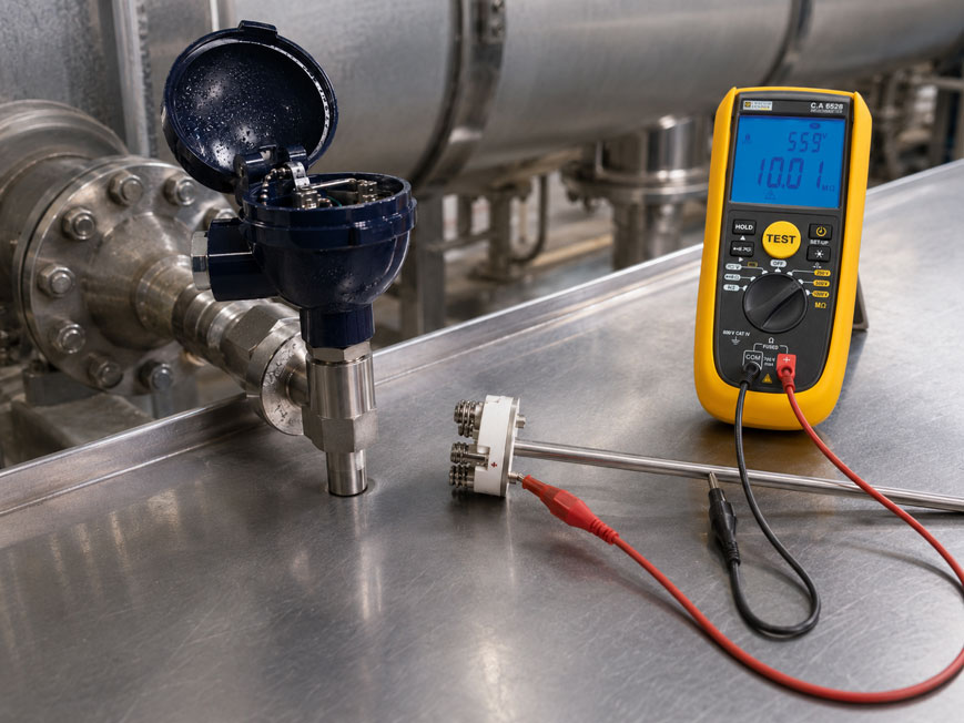
A Pt100 can still provide an apparently plausible resistance value electrically while measuring incorrectly if the insulation between the measuring circuit and the metallic sensor sheath is impaired.
Such insulation faults are particularly difficult to identify because they do not always appear as an obvious sensor break or short circuit. Instead, the temperature indication may drift slowly, show different values under humid conditions than when dry, or change seemingly inexplicably with the sensor temperature.
Typical causes include moisture ingress in the connection head, damaged connection cables, contaminated terminals, aged insulation materials or electrical contact between the measuring circuit and the metallic sheath of the measuring insert.
A normal resistance test between the Pt100 connection wires is therefore not always sufficient. If suspicious measured values occur, the insulation resistance between the measuring circuit and the metallic sheath should also be checked.
According to DIN EN 60751, the insulation resistance between the measuring circuit and the sheath must be sufficiently high during the corresponding test. Insufficient insulation resistance creates an additional electrical path and can, in particular, result in a temperature indication that is too low.
For industrial applications with a replaceable measuring insert, the WIKA TR10-B resistance thermometer, for example, is suitable. The spring-loaded measuring insert can be removed from the thermowell and checked or replaced separately.
The WIKA TR10-A is available as a replacement measuring insert. Further solutions can be found under resistance thermometers and Pt100 sensors as well as in the complete range of temperature measurement technology at ICS Schneider.
Table of Contents
- How does a Pt100 work?
- What is a Pt100 insulation fault?
- Why does poor insulation resistance distort the temperature value?
- What does a short to sheath mean?
- How does moisture enter a temperature sensor?
- Why can the fault be temperature-dependent?
- Typical symptoms of an insulation fault
- Distinguishing insulation faults from other Pt100 faults
- First check the plausibility of the Pt100 resistance
- Measuring insulation resistance correctly
- What insulation resistance is required?
- Disconnect transmitters and electronics before insulation testing
- Check the connection head and terminals
- Inspect the connection cable separately
- Consider the measuring insert and thermowell separately
- 2-, 3- and 4-wire circuits: What changes in the event of an insulation fault?
- Can a damp Pt100 simply be dried?
- Practical example: temperature value drifts after a plant shutdown
- Typical fault patterns
- Recommended diagnostic procedure
- When should the sensor be replaced?
- Suitable Pt100 technology from ICS Schneider
- Conclusion
- FAQ
How does a Pt100 work?
A Pt100 is a platinum resistance sensor whose electrical resistance changes in a defined manner with temperature.
At:
0 °C
the nominal resistance is:
100 Ω
Between 0 °C and 100 °C, the sensitivity is approximately:
0.385 Ω/K
At 100 °C, an ideal Pt100 therefore has approximately:
138.5 Ω
The connected evaluation electronics apply a small measuring current, measure the voltage drop and calculate the resistance and subsequently the temperature from it.
For correct measurement, the current must follow the intended measuring path
Ideally, the measuring current flows exclusively through:
- connection cable,
- Pt100 measuring element,
- return conductor.
If an additional unwanted electrical path to the metallic sheath or ground is created, the electrical measuring circuit changes.
This is where the insulation fault begins.
What is a Pt100 insulation fault?
The electrical conductors of the Pt100 must be sufficiently insulated from the metallic sensor sheath.
This insulation is not an ideal infinitely high resistance, but it should be sufficiently high that practically no relevant measuring current can flow through the sheath.
Damaged insulation creates a leakage-current path
This can, for example, occur between:
- the Pt100 connection wire and the measuring insert sheath,
- the measuring circuit and protective-earth potential,
- damp connection terminals and the connection head,
- a damaged cable and a grounded machine structure.
The fault does not necessarily have to be low-resistance.
Even a resistance of several tens or hundreds of kiloohms can already have a measurable effect on a Pt100.
This distinguishes an insulation fault from a conventional short circuit
With a complete short circuit, the fault is usually obvious.
With a medium- or high-resistance insulation fault, however, the Pt100 remains electrically measurable and often provides values that initially appear plausible.
Why does poor insulation resistance distort the temperature value?
A Pt100 is evaluated through its resistance.
If an additional conductive path is created in parallel with the actual measuring circuit, the total resistance detected by the electronics changes.
A parallel resistance reduces the resulting resistance
In simplified terms, the following applies to two parallel resistances:
Rtotal = (RPt100 · Rins) / (RPt100 + Rins)
If the insulation resistance is very high, its influence is practically negligible.
However, if it drops significantly, the measured total resistance becomes lower.
Since a Pt100 has a positive temperature coefficient, the evaluation electronics typically interpret a lower resistance as a lower temperature.
The effect may initially appear surprisingly small
For a Pt100, approximately:
0.385 Ω ≈ 1 K
A resistance error of only a few tenths of an ohm can therefore already become clearly noticeable.
For example, WIKA specifies that with an insulation resistance of:
100 kΩ
a possible resistance error of up to approximately:
0.25 Ω
may occur.
In the range around 0 °C, this corresponds approximately to:
0.65 K
At:
25 kΩ
the error can reach approximately:
1 Ω
.
This corresponds approximately to:
2.6 K
An insulation fault therefore does not have to be an obvious short circuit to cause a relevant temperature deviation.
What does a short to sheath mean?
A short to sheath is an unwanted electrical contact between the actual measuring circuit and the metallic outer sheath of the temperature sensor or measuring insert.
In the extreme case, almost direct contact exists
A normal multimeter can then already detect a low resistance between a connection wire and the metallic sheath.
However, the fault often begins with a relatively high resistance
For example due to:
- moisture,
- contaminated insulation surfaces,
- mechanically damaged internal insulation,
- thermally aged insulation material.
The transition from good insulation to an actual short to sheath can therefore occur gradually.
A simple continuity test often does not detect such early-stage faults.
How does moisture enter a temperature sensor?
Moisture can enter a temperature measuring point at various locations.
Typical entry points include
- insufficiently tightened cable glands,
- cable diameters unsuitable for the seal used,
- damaged cover seals,
- open or poorly closed connection heads,
- damaged connection cables,
- connectors with insufficient sealing.
Condensation can also play a role
A connection head can become warm during operation and cool down again after shutdown.
During cooling, humid ambient air can enter the housing or moisture already present in the air can condense.
This can create thin conductive moisture films on:
- terminals,
- ceramic parts,
- circuit boards,
- insulation surfaces
.
Contamination increases the effect
Pure water is relatively poorly conductive.
However, if the moisture contains:
- salts,
- dust,
- process residues,
- corrosion products
the insulation resistance can decrease much more significantly.
Why can the fault be temperature-dependent?
A damaged Pt100 does not necessarily show the same deviation at every temperature.
Moisture can change with temperature
When heated, existing moisture can partially evaporate or be displaced from a critical location.
The insulation resistance may then temporarily increase.
After cooling, condensation can form again and the fault may reappear.
Insulation materials themselves are also temperature-dependent
With damaged or aged insulation materials, the resistance can change with temperature.
A sensor may therefore, for example:
- appear normal at room temperature,
- drift at high temperature,
- show a different zero point again after cooling.
This behavior makes troubleshooting particularly difficult
If the sensor is tested only in a cold, dry workshop environment, the insulation fault may not be reproducible.
For intermittent faults, it should therefore be considered under which:
- temperature conditions,
- humidity conditions,
- operating periods
the deviation actually occurs.
Typical symptoms of an insulation fault
An insulation problem can manifest itself in many different ways.
Typical indications include
- temperature indication drifts slowly,
- indication differs after plant shutdown compared with continuous operation,
- deviation depends on humidity or cleaning,
- temperature tends to be indicated too low,
- several calibration points do not show a constant deviation,
- measured value changes unusually after heating or cooling,
- fault appears to disappear after drying but returns later,
- measured value reacts to touching or moving the connection cable,
- a finite resistance can be measured between a connection wire and the metallic sensor sheath.
Not every one of these symptoms proves an insulation fault
Other problems can cause similar effects.
The measuring point should therefore be systematically separated into its individual components and tested.
Distinguishing insulation faults from other Pt100 faults
| Fault type | Typical behavior | Test |
|---|---|---|
| Lead resistance in 2-wire connection | usually relatively constant positive temperature error | check lead resistance and connection type |
| Asymmetrical 3-wire connection | residual error despite lead-resistance compensation | compare individual resistance values of the three wires |
| Sensor break | very high or infinite resistance, often diagnostic message | check continuity |
| Short circuit between measuring wires | very low resistance, extremely low temperature value or fault message | measure resistance between wires |
| Insulation fault to sheath | drift, often indication too low, temperature- or moisture-dependent | measure insulation resistance to metallic sheath |
| Faulty transmitter | Pt100 resistance plausible, but output signal incorrect | check sensor and transmitter separately |
| Incorrect sensor type configured | systematically incorrect characteristic curve | check input configuration |
| Thermal installation error | sensor electrically correct, but actual sensor temperature does not correspond to process temperature | check insertion length, heat dissipation and reference measurement |
First check the plausibility of the Pt100 resistance
Before carrying out an insulation test, the normal Pt100 measuring circuit should be checked.
1. Electrically disconnect the sensor from the evaluation unit
The transmitter, PLC input or temperature indicator must not influence the resistance measurement.
2. Measure the Pt100 resistance
At approximately:
0 °C
the resistance should be around:
100 Ω
.
At approximately:
100 °C
approximately:
138.5 Ω
should be expected.
3. Consider the ambient temperature
A Pt100 at 20 °C will, of course, not have exactly 100 Ω.
For a quick plausibility check, the value at room temperature is approximately in the range:
107 … 108 Ω
4. Compare wires in a 3-wire circuit
The two same-colored connection wires or wires assigned to the same side of the sensor should have plausible and comparable lead resistances.
Large differences can indicate:
- poor terminal connections,
- corrosion,
- partial cable break
.
Measuring insulation resistance correctly
A normal resistance measurement only answers the question of whether the Pt100 measuring circuit itself is plausible.
To assess the insulation, an additional measurement is made between the measuring circuit and the metallic sheath.
Typical test setup
The sensor or measuring insert is completely disconnected from any connected electronics.
The insulation resistance is then measured between:
- the Pt100 measuring circuit or connection wires,
- the metallic sheath of the measuring insert.
For a basic test, the wires belonging to the same measuring circuit can be considered together and tested against the sheath.
For detailed troubleshooting, individual wires can also be measured separately against the sheath.
A normal multimeter resistance range is often insufficient for this purpose
A suitable insulation tester is required that can reliably measure high resistance values in the:
MΩ or GΩ range
.
What insulation resistance is required?
According to DIN EN 60751, the insulation resistance between the measuring circuit and the metallic sheath must not fall below a defined level during the corresponding test.
As a minimum requirement, at a test voltage of at least:
100 V DC
an insulation resistance of at least:
100 MΩ
is specified.
A good new sensor is typically significantly above this value
According to WIKA, its resistance thermometers are tested with:
500 V DC
and must achieve:
> 1,000 MΩ
A measured value of only a few hundred kiloohms is therefore by no means “still sufficiently high”
For a Pt100, this already represents a significant insulation fault and can noticeably influence the measuring result.
However, the manufacturer documentation or test specification applicable to the specific sensor should always be taken into account when evaluating the result.
Disconnect transmitters and electronics before insulation testing
An insulation test uses a significantly higher test voltage than a normal resistance measurement.
This voltage must not be applied uncontrollably to connected electronics.
Before testing, it may therefore be necessary to disconnect
- head-mounted transmitters,
- PLC inputs,
- temperature indicators,
- signal converters,
- isolating amplifiers,
- other electronic inputs.
The insulation test should only be performed on the intended, de-energized sensor circuit and in accordance with the device or manufacturer instructions.
A directly connected temperature transmitter must not simply be subjected to the insulation-test voltage intended for the bare measuring insert.
Check the connection head and terminals
Not every poor insulation value means that the Pt100 element itself is damaged.
The fault may already be located in the connection head.
With the connection head open, check for
- visible moisture,
- water droplets,
- condensation marks,
- corrosion on terminals,
- greenish or white corrosion products,
- contaminated ceramic bases,
- damaged wire insulation,
- correct seating of the cable gland,
- condition of the cover seal.
A comparison measurement is particularly useful
First, the complete measuring point including the connection head is tested.
The measuring insert or sensor cable is then disconnected.
If the insulation resistance improves significantly afterwards, the cause may be:
- in the connection head,
- at the terminals,
- in the external wiring.
If the value remains poor even when the measuring insert is tested separately, the sensor itself is suspect.
Inspect the connection cable separately
A long field cable between the Pt100 and the control cabinet can also cause an insulation fault.
Typical damage includes
- crushed cables,
- abraded cable jackets,
- damaged cable glands,
- moisture in junction boxes,
- oil or coolant in connectors,
- mechanical damage in drag chains.
For troubleshooting, a distinction should therefore be made between:
Sensor/measuring insert
and:
Field wiring
Test the sensor directly at the connection head
If the insulation value is good there but poor when measured at the control cabinet, the fault is very likely in the cable or wiring between the two points.
Consider the measuring insert and thermowell separately
In industrial resistance thermometers such as the WIKA TR10-B, the actual Pt100 is located in a replaceable measuring insert.
This measuring insert is inserted into a separate thermowell.
This separation is useful for electrical diagnostics
The measuring insert can be removed and tested separately.
This makes it possible to distinguish between:
- a defective measuring insert,
- problems in the connection head,
- the outer thermowell or process connection.
Replacement therefore does not necessarily have to involve the entire measuring point
If the thermowell remains mechanically and process-technically sound, only the measuring insert may need to be replaced in a suitable design.
The WIKA TR10-A, for example, is specifically intended as a replacement measuring insert for service applications.
2-, 3- and 4-wire circuits: What changes in the event of an insulation fault?
2-, 3- and 4-wire technology is primarily used to reduce the influence of normal lead resistance on Pt100 measurement.
2-wire
The resistance of both connection wires directly affects the measuring result.
3-wire
Lead resistance is largely compensated, provided that the individual lead resistances are sufficiently symmetrical.
4-wire
The influence of the connection wires can be almost completely eliminated from the measurement.
However, an insulation fault is not eliminated by any of these methods
An unwanted current path from the measuring circuit to the sheath remains present even with a 3- or 4-wire connection.
A more accurate connection method therefore cannot compensate for insufficient insulation resistance.
Can a damp Pt100 simply be dried?
This depends on where the moisture is located and how it entered.
Moisture only in the connection head
If only the connection compartment is damp, depending on its condition, the problem may be resolved by:
- careful drying,
- cleaning contaminated insulation surfaces,
- replacing damaged seals,
- correct installation of the cable gland
.
The measurement must then be repeated
What matters is not that the connection head looks dry, but that the insulation resistance subsequently remains stable within the permissible range.
Moisture in the actual measuring insert
If moisture has penetrated the internal sensor or mineral-insulated cable, a temporarily improved result after heating should not automatically be considered a permanent repair.
The cause of the moisture ingress may still be present.
In the event of recurring insulation problems
replacing the measuring insert is often the more reliable solution.
Practical example: temperature value drifts after a plant shutdown
A Pt100 monitors the temperature of a process vessel.
During normal continuous operation, the measuring point indicates approximately:
85 °C
and largely agrees with a reference measurement.
After an extended plant shutdown
the sensor indicates several Kelvin too low during restart.
After several hours of operation, the measured value gradually approaches the expected value again.
Initial suspicion
The temperature transmitter is assumed to be unstable.
Checking the Pt100 resistance
The sensor resistance at room temperature is fundamentally plausible.
There is neither a sensor break nor a direct short circuit between the measuring wires.
Insulation test
Immediately after the cold plant shutdown, however, only a resistance in the lower MΩ range is measured between the Pt100 measuring circuit and the metallic measuring-insert sheath.
After extended warm operation, this value increases significantly.
Cause
Moisture is present in the connection area or measuring insert.
When heated, the insulation improves temporarily.
After cooling, condensation occurs again.
Corrective action
The leak at the connection head is eliminated and the affected measuring insert is replaced.
After the repair, the following are checked again:
- Pt100 resistance,
- insulation resistance,
- temperature indication compared with a reference.
This example shows why a Pt100 can initially appear completely intact during a simple resistance measurement even though the actual fault lies in the insulation to the metallic sheath.
Typical fault patterns
| Observation | Possible cause | Recommended check |
|---|---|---|
| Temperature permanently too low | insulation resistance too low or leakage path | check measuring circuit against sheath |
| Temperature permanently too high | lead resistance with 2-wire connection | check lead resistance and connection type |
| Measured value drifts after cleaning | moisture in the connection head | check cable gland, seal and terminals |
| Measured value incorrect when cold and better when warm | moisture-dependent insulation fault | compare insulation resistance in cold and warm condition |
| Measured value becomes increasingly unstable as temperature rises | temperature-dependent insulation damage | test sensor at several temperatures |
| Pt100 resistance plausible but process value still incorrect | insulation fault, transmitter or thermal installation error | separate the measuring chain step by step |
| Low resistance between wire and sheath | short to sheath | replace measuring insert or perform manufacturer test |
| Insulation value good directly at sensor but poor at control cabinet | field cable damaged or damp | test wiring separately |
| Insulation value increases significantly after drying | moisture is a likely cause | find entry point and perform repeat test |
| Measured value changes when the cable is moved | cable break or damaged insulation | test cable section by section |
| Display jumps to fault value | open measuring circuit or hard short circuit | check continuity and wire resistances |
| Only one of two Pt100 measuring circuits in the same sensor fails | fault in an individual sensor circuit | test both measuring circuits separately |
| Fault remains after replacing the measuring insert | field wiring or evaluation electronics | test cable and transmitter separately |
Recommended diagnostic procedure
- Document the fault pattern: Record deviation, temperature, humidity and operating condition.
- Check the plausibility of the process value: Compare with an independent temperature reference if possible.
- Check the sensor type: Ensure that Pt100 and the correct characteristic curve are configured.
- Check the connection type: Correctly identify 2-, 3- or 4-wire connection.
- De-energize the measuring point: Disconnect the sensor from the evaluation electronics.
- Measure Pt100 resistance: Compare the value with the current temperature.
- Check continuity of all wires: Rule out interruptions.
- Compare lead resistances in 3-wire circuits: Detect significant asymmetries.
- Check for a direct short to sheath: Measure resistance between connection wires and metallic sheath.
- Prepare the insulation tester: Select a suitable test voltage according to sensor or manufacturer requirements.
- Completely disconnect electronics: Do not apply high test voltage to transmitters or PLC inputs.
- Measure insulation resistance: Test measuring circuit against metallic measuring-insert sheath.
- Evaluate the result: Apply standard and manufacturer limits.
- Open the connection head: Check for moisture, corrosion and contamination.
- Check the cable gland: Check seal and cable diameter.
- Test the field cable separately: Separate the sensor and connection cable from each other.
- Test the measuring insert separately: Remove and measure individually if the design allows replacement.
- Investigate temperature dependence: Compare cold and warm conditions if necessary.
- Locate the fault: Clearly assign it to the sensor, connection head, cable or transmitter.
- Repair or replace: Permanently eliminate the cause.
- Repeat the insulation test: Confirm the improvement by measurement.
- Verify the temperature measurement: Finally check the measuring point against a reference temperature.
- Document the result: Record resistance values, insulation values and replaced components.
When should the sensor be replaced?
A Pt100 does not have to be completely replaced immediately whenever an abnormality occurs.
Replacing the measuring insert is particularly advisable in the event of
- a confirmed short to sheath,
- insulation resistance below the permissible limit,
- recurring moisture ingress into the measuring insert,
- significant temperature-dependent drift,
- mechanically damaged mineral-insulated cable,
- corroded internal connections,
- non-reproducible calibration.
Repairing the connection area may be sufficient if
- the measuring insert itself has a faultless insulation value,
- moisture is present only in the connection head,
- seals or cable glands have been clearly identified as the cause.
After every repair, the complete measuring point should be checked again electrically and with respect to temperature measurement.
Suitable Pt100 technology from ICS Schneider
WIKA TR10-B – resistance thermometer with replaceable measuring insert
The WIKA TR10-B is designed for installation in a separate thermowell and is therefore particularly suitable for industrial process measuring points where maintainability is important.
Key features include:
- Sensor ranges: -196 … +600 °C,
- Pt100 or Pt1000 sensors,
- 2-, 3- and 4-wire circuits depending on version,
- spring-loaded and replaceable measuring insert,
- combination with different thermowell designs,
- optional analog or digital head-mounted transmitters,
- numerous explosion-protected versions.
The replaceable measuring insert is particularly advantageous for service and diagnostic work.
If an insulation fault is confirmed, the measuring insert can be removed, tested separately and replaced if necessary without having to remove the complete thermowell from the process.
WIKA TR10-A – replacement measuring insert
The WIKA TR10-A is specifically designed as a measuring insert for resistance thermometers and as a replacement component for service applications.
Key features include:
- sensor ranges from -196 … +600 °C,
- mineral-insulated sheathed cable,
- spring-loaded design,
- different sensor types and connection methods,
- optional transmitter mounting.
This allows a damaged or poorly insulated measuring insert to be replaced specifically in suitable thermometer designs.
WIKA TR10-C – threaded resistance thermometer
The WIKA TR10-C is screwed directly into the process and also features a spring-loaded, replaceable measuring insert.
With this design, the actual sensor unit can therefore also be removed for:
- inspection,
- measuring-equipment monitoring,
- calibration,
- replacement during service
.
Further devices can be found under resistance thermometers and Pt100 sensors at ICS Schneider.
Conclusion
A Pt100 insulation fault is one of the faults that can easily be overlooked during a normal resistance measurement.
A plausible Pt100 resistance does not prove that the insulation is intact
The measuring circuit can be electrically continuous while still having an unwanted leakage path to the metallic sheath.
Moisture is a typical cause
It can enter via the connection head, cable gland, cable or damaged sensor components and significantly reduce the insulation resistance.
A short to sheath is the pronounced form of an insulation fault
A low-resistance contact between the measuring circuit and the metallic sheath is a clear indication of a defective measuring insert or sensor.
The deviation can be temperature-dependent
Moisture, condensation and aged insulation materials can cause the fault to behave differently in cold and warm conditions.
3- or 4-wire technology does not solve the problem
These circuits reduce lead-resistance errors but cannot compensate for an electrical leakage path to the sheath.
The insulation resistance must be tested separately
The test is performed between the Pt100 measuring circuit disconnected from the measuring instrument and the metallic sheath using a suitable insulation measuring instrument.
Electronics must be disconnected beforehand
The high test voltage of an insulation measurement must not be applied uncontrollably to head-mounted transmitters, PLC inputs or other electronic components.
Replaceable measuring inserts simplify service
With thermometers such as the TR10-B or TR10-C, a faulty measuring insert can be specifically tested or replaced.
For practical applications
Document the fault pattern → compare the process value with a reference → disconnect the Pt100 from the measuring instrument → check measuring-circuit resistance → check wires and lead resistances → measure insulation resistance against the metallic sheath → inspect the connection head for moisture and corrosion → test sensor and field cable separately → compare cold and warm conditions for intermittent faults → clearly locate the fault → replace the measuring insert or damaged components → recheck the insulation value → finally verify the temperature measuring point.
FAQ: Diagnosing Pt100 Insulation Faults Correctly
What is a Pt100 insulation fault?
An insulation fault exists when the electrical resistance between the Pt100 measuring circuit and the metallic sheath or another unwanted potential becomes too low.
What does a short to sheath mean on a Pt100?
A short to sheath is an unwanted electrical contact between a sensor wire or the measuring circuit and the metallic sensor sheath.
How does poor insulation resistance affect the measurement?
It can distort the resistance detected by the measuring instrument. This can typically result in a temperature indication that is too low.
Can a Pt100 still have a plausible resistance despite an insulation fault?
Yes. This is precisely why such faults are often not detected by a normal resistance measurement between the Pt100 wires.
How do you test the insulation resistance of a Pt100?
The measuring circuit, disconnected from the evaluation unit, is tested against the metallic sensor sheath using a suitable insulation tester.
How high must the insulation resistance be?
According to DIN EN 60751, a minimum value of 100 MΩ is specified for the corresponding test between measuring circuit and sheath at at least 100 V DC.
How high is the insulation resistance of a good new sensor?
It is typically significantly above the minimum value. For example, WIKA tests its resistance thermometers at 500 V DC for an insulation resistance of more than 1,000 MΩ.
Can I perform the insulation test with a normal multimeter?
A multimeter can detect a hard short to sheath. However, a suitable insulation tester is required for a meaningful test of very high insulation resistances.
Can I apply 500 V directly to a connected Pt100 transmitter?
No. Electronic devices must be disconnected before such an insulation test in accordance with the manufacturer’s instructions so that the test voltage does not damage the electronics.
Why does an insulation fault often result in a temperature indication that is too low?
An additional conductive path can reduce the effective resistance detected by the evaluation electronics. A Pt100 interprets a lower resistance as a lower temperature.
What is the sensitivity of a Pt100?
In the range around 0 °C, the resistance changes by approximately 0.385 Ω per Kelvin.
What does Pt100 mean?
Pt stands for platinum and 100 for a nominal resistance of 100 Ω at 0 °C.
Can moisture cause incorrect Pt100 measurements?
Yes. Moisture can create conductive paths between terminals, sensor wires and metallic housing components, thereby reducing the insulation resistance.
Where does moisture typically enter?
Common entry points include cable glands, damaged seals, connection heads and damaged connection cables.
Can condensation form in the connection head?
Yes. Temperature changes can cause moisture present in the air inside the connection compartment to condense.
Why does the fault sometimes occur only when the sensor is cold?
Condensation can form after cooling. When heated, the moisture can partially evaporate again and the insulation resistance may temporarily increase.
Can the fault also occur only at high temperature?
Yes. Damaged or aged insulation materials can react to temperature, causing the insulation resistance to become critical only when heated.
Does a 3-wire circuit help against insulation faults?
No. A 3-wire circuit primarily compensates for lead resistance, not for a leakage path between the measuring circuit and the sheath.
Does a 4-wire circuit help?
A 4-wire circuit also cannot compensate for a genuine insulation fault.
What is the difference between lead resistance and an insulation fault?
Lead resistance is in series with the Pt100 and typically causes an excessively high measured value in 2-wire measurements. An insulation fault, on the other hand, forms an unwanted additional current path and can reduce the effective resistance.
How do I detect a sensor break?
In the event of a complete sensor break, a very high or infinite resistance is measured between the corresponding connection wires.
How do I detect a short circuit?
In the event of a short circuit between sensor wires, a resistance that is significantly too low is measured.
What should I check first: the Pt100 or the transmitter?
For clear diagnostics, the sensor and transmitter should be considered separately. First, the Pt100 resistance can be measured directly, after which the evaluation electronics can be tested separately.
Can a temperature transmitter detect an insulation fault?
Some transmitters have diagnostic functions for sensor break and short circuit. However, a medium- or high-resistance insulation fault may not necessarily be detected unambiguously.
Can a damp sensor be dried and reused?
If the moisture was present only in the connection compartment and the cause of ingress has been permanently eliminated, this may be possible. However, the insulation resistance must be checked again afterwards.
When should the Pt100 be replaced?
Replacement is advisable in the event of a confirmed short to sheath, permanently insufficient insulation resistance, recurring moisture ingress or non-reproducible measurement.
Does the complete thermometer have to be replaced on a TR10-B?
Not necessarily. The TR10-B has a replaceable, spring-loaded measuring insert. If the thermowell is still in good condition, only the measuring insert may need to be replaced.
Which measuring insert is suitable as a replacement component?
The WIKA TR10-A is specifically intended, among other applications, as a replacement measuring insert for service cases.
Where can I find further Pt100 resistance thermometers?
Further solutions can be found under resistance thermometers and Pt100 sensors at ICS Schneider.