


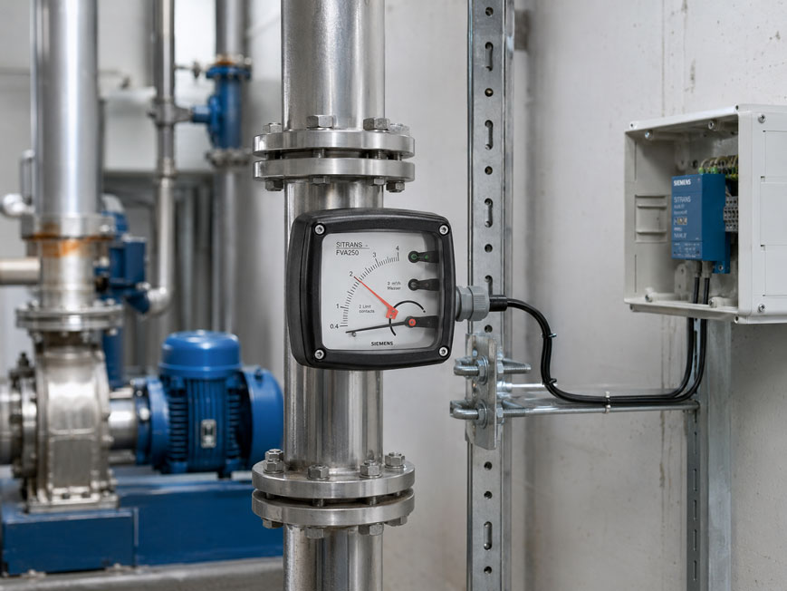
A variable-area flowmeter with limit switches combines a directly readable local flow indication with simple electrical min./max. monitoring, without necessarily requiring a continuous 4–20 mA signal to be processed by a PLC.
This is particularly useful for cooling, purging, gas and utility circuits where the operator should be able to see the current flow locally, while the automation system only needs to know whether a defined minimum or maximum flow is being maintained.
One or two limit switches monitor specific positions of the mechanical indicator. If the set limit value is exceeded or undershot, the electrical switching signal changes.
This can be used, for example, to control a warning light, relay, switching amplifier or digital PLC input, while the actual flow indication remains directly visible on the measuring instrument.
However, it is important to distinguish between a conventional potential-free switching contact and a NAMUR limit sensor. A NAMUR sensor is not a power switch and must not simply be used like a relay contact to switch larger loads directly. It requires a suitable NAMUR evaluation unit or switching amplifier.
A particularly suitable instrument from the ICS portfolio is the Siemens SITRANS FVA250 variable-area flowmeter. It has a local mechanical display and is optionally available with one or two limit switches. Alternatively, the instrument can also be equipped with a MEM transmitter and 4–20 mA/HART output.
Further solutions can be found under variable-area flowmeters and in the complete range of flow measurement technology at ICS Schneider.
Table of Contents
- How does a variable-area flowmeter work?
- Why is the principle particularly suitable for local indication?
- What does a limit switch do?
- Distinguishing minimum, maximum and window monitoring
- When is a switching contact sufficient instead of 4–20 mA?
- Understanding NAMUR limit sensors correctly
- Evaluating the limit switch electrically
- Considering hysteresis and fluctuating flow
- Setting the switching point sensibly
- Observe mounting position and flow direction
- Consider medium data and scaling
- Special considerations for gases
- Avoid pulsations and an oscillating float
- Consider pressure loss and operating pressure
- Do not confuse a limit switch with a safety function
- Practical example: monitoring cooling-water flow
- Typical fault patterns
- Recommended design and commissioning procedure
- Suitable flow measurement technology from ICS Schneider
- Conclusion
- FAQ
How does a variable-area flowmeter work?
With the variable-area measuring principle, a movable float is located in a flow cross-section whose free area increases as the float rises.
The medium typically flows through the instrument from bottom to top.
The float is subject to forces including:
- gravitational force,
- buoyancy,
- flow force.
As the flow increases, the float rises until a mechanical equilibrium is established.
Its position then corresponds to a specific flow value.
In a metal-tube variable-area flowmeter
the float is not directly visible from the outside.
Its movement is transmitted magnetically to the indicator unit located outside the pressure-retaining measuring tube.
With the SITRANS FVA250, the current flow is therefore shown directly on a scale.
Why is the principle particularly suitable for local indication?
For purely mechanical flow indication, the FVA250 does not require electrical measured-value transmission.
The operator can read the current value directly from the scale.
This is practical, for example, in
- cooling-water circuits,
- shielding-gas supplies,
- purge-air and purge-gas systems,
- lubricant supply systems,
- dosing lines,
- local auxiliary consumers,
- machine and plant units.
In such applications, it is often unnecessary to continuously acquire every individual flow value in the PLC.
For plant monitoring, information such as the following may be sufficient:
Flow sufficient: YES / NO
or:
Flow within permissible window: YES / NO
Limit switches can be used precisely for this purpose.
What does a limit switch do?
A limit sensor monitors whether the mechanical indicator reaches or passes a defined position.
It therefore converts a specific flow condition into a binary electrical signal.
Unlike an analog output
the limit switch does not continuously indicate whether, for example:
18.2 l/min
or:
22.7 l/min
is flowing.
It essentially answers only whether the defined limit value has been reached, exceeded or undershot.
Example
Minimum flow:
15 l/min
Above the limit value, the process is within the permissible range.
If the flow indication drops below the defined position, the limit sensor can trigger a fault signal.
Distinguishing minimum, maximum and window monitoring
Depending on the application, one or two limit values may be useful.
Minimum monitoring
One limit sensor monitors a minimum flow.
Typical applications:
- insufficient cooling water,
- missing lubrication,
- insufficient purge-gas flow,
- dry-running protection or process enable.
Maximum monitoring
One limit sensor monitors a maximum permissible flow.
This may be useful, for example, for:
- limited gas supply,
- dosing processes,
- unusually high consumption,
- detection of an open bypass or a leak.
Minimum/maximum or window monitoring
Two limit sensors can be used to define a permissible flow window.
For example:
Min = 15 l/min
Max = 25 l/min
This makes it possible to electrically determine whether the flow is:
- too low,
- within the permissible range,
- too high
.
The SITRANS FVA250 is available, among other versions, with one or two limit switches.
When is a switching contact sufficient instead of 4–20 mA?
Not every flow measuring point requires a continuous analog value.
A limit switch is often sufficient when
- only a minimum flow needs to be monitored,
- only exceeding or falling below a limit is relevant,
- the exact value can be read locally by the operator,
- no trend recording is required,
- no continuous control is performed using the measured value.
A 4–20 mA output is useful, however, when
- the current flow must be displayed in the control room,
- the flow must be stored or logged,
- a process variable is controlled to a setpoint,
- several alarm limits are to be generated in software,
- trend analysis or consumption evaluation is required.
The decision is therefore not whether analog or digital is better, but which process information is actually required.
Understanding NAMUR limit sensors correctly
In the SITRANS FVA250 version with limit switches, inductive NAMUR limit sensors are used.
Siemens specifies the following type for the limit switch:
SJ3.5-N-BU
with the switching function:
NAMUR NC
.
A NAMUR sensor is not a potential-free relay contact
It operates with a defined current signal and is normally connected to a:
- NAMUR switching amplifier,
- isolating switching amplifier,
- suitable NAMUR input
.
The evaluation unit then converts this into a usable binary switching signal.
Why is this distinction important?
If the specification simply states “switching contact”, it could incorrectly be assumed that the sensor can directly switch:
- a 230 V warning light,
- a contactor,
- a solenoid valve
.
This is not the case with a NAMUR limit sensor.
The electrical evaluation must match the contact technology used.
Evaluating the limit switch electrically
A typical measuring chain may consist of:
FVA250 limit sensor → NAMUR switching amplifier → relay output → alarm / PLC digital input
Without a PLC
the relay output of a suitable switching amplifier can, for example, control:
- a warning light,
- an audible alarm,
- an enable circuit.
With a PLC
only a digital input is required.
An analog 4–20 mA input module is not required for pure limit monitoring.
With two limit switches, two separate digital states can be evaluated.
In the version with two contacts, the FVA250 limit sensors are electrically isolated from each other.
Considering hysteresis and fluctuating flow
A real process rarely remains perfectly stable at a single flow value.
Pumps, valves, pressure regulators and consumers can cause small fluctuations.
This becomes problematic directly at the switching point
If the actual flow remains permanently close to the limit value, the switching signal may change frequently.
This behavior is often perceived as:
chattering
or:
cycling
of the signal.
The design should therefore take into account
- process fluctuations,
- switching hysteresis of the limit system,
- required safety margin,
- if necessary, a time delay in the evaluation.
A short software- or relay-based delay can, for example, prevent a very brief flow drop from immediately causing a plant shutdown.
Whether such a delay is permissible depends on the respective process and safety function.
Setting the switching point sensibly
The limit value should not automatically be set exactly at the lowest technically permissible process value.
Cooling example
The machine manufacturer specifies:
absolute minimum flow = 10 l/min
The normal operating flow is:
18 l/min
A warning switching point could, for example, be set clearly above the critical limit.
This provides time to respond to a developing deterioration before the actual minimum supply is undershot.
The following should be considered when setting the limit
- normal setpoint,
- permissible process variation,
- critical minimum or maximum value,
- process response time,
- measurement deviation of the flowmeter,
- supply fluctuations.
The limit switch should monitor a meaningful process limit rather than simply an arbitrary point on the scale.
Observe mounting position and flow direction
The specified mounting position for the SITRANS FVA250 is:
vertical
with a flow direction:
from bottom to top
.
This follows directly from the measuring principle.
Gravity, buoyancy and flow force must act on the float in the intended orientation.
Incorrect mounting can
- shift the indication,
- impair float movement,
- distort limit-switch activation.
Especially with an instrument equipped with limit switches, it is therefore not sufficient for the indication to be approximately correct.
The mechanical system must operate reproducibly so that the defined switching point is reached reliably.
Consider medium data and scaling
A variable-area flowmeter is designed for specific medium and operating conditions.
The resulting float position depends, among other factors, on:
- medium density,
- viscosity,
- pressure,
- temperature,
- for gases, additionally the actual operating conditions.
The instrument therefore cannot simply be transferred between different media
For example, an instrument designed for water must not be regarded as an accurately scaled flowmeter for a liquid with significantly different density or viscosity without first checking the application.
The same applies to the limit value.
If the indicated flow is incorrect because the medium data are incorrect, the actual flow at which the limit switch activates will also differ from the assumed value.
Special considerations for gases
For gases, volumetric flow depends strongly on pressure and temperature.
It must therefore be clearly defined which operating or reference conditions the scale refers to.
When gas conditions change
the same actual mass flow can correspond to a different operating volumetric flow.
For correct sizing, at least the following should therefore be known:
- gas type,
- minimum and maximum flow,
- operating pressure,
- operating temperature,
- required unit or reference conditions.
The limit value must refer to the same defined conditions as the flow scale.
Avoid pulsations and an oscillating float
A limit sensor can only operate stably if the mechanical flow indication is sufficiently stable.
Pulsating flows can cause the float and pointer to oscillate around an average value.
Typical causes include
- piston or diaphragm pumps,
- fast-switching valves,
- unstable pressure regulators,
- pressure surges,
- gas bubbles in liquids,
- mechanical pipe vibrations.
If the switching point lies within this fluctuation range, the limit sensor may repeatedly activate and reset.
Float damping is available for the SITRANS FVA250
Siemens recommends damping, among other cases:
- generally for gas measurements,
- when gas bubbles in the medium cannot be avoided,
- in the event of pressure surges,
- with turbulent or pulsating flow,
- with unavoidable pipe vibrations.
This stabilizes the mechanical indication and can also make limit monitoring more robust.
Consider pressure loss and operating pressure
A variable-area flowmeter inherently causes a pressure loss.
This must be taken into account when designing the supply system.
Particularly with gases, insufficient operating pressure can result in unstable behavior.
For the SITRANS FVA250, Siemens specifies the following minimum operating pressure:
Operating pressure > 2 × pressure loss
The actual pressure loss depends on the measuring range and instrument version.
When planning the installation, the following should therefore be considered together
- supply pressure,
- backpressure,
- pressure loss of the measuring instrument,
- pressure loss of valves and piping,
- minimum and maximum flow.
Do not confuse a limit switch with a safety function
An electrical limit switch can be part of machine or process monitoring.
However, this does not automatically mean that the complete measuring chain is suitable for a functional safety function.
A safety function may additionally require
- a suitable sensor architecture,
- fault detection,
- a defined evaluation unit,
- suitable final switching elements,
- verification of the required safety integrity.
Whether a simple limit signal serves only as operational monitoring or forms part of a safety-related shutdown must already be defined during plant planning.
A limit sensor does not automatically replace a flow monitor designed specifically for the requirements of the respective safety function.
Practical example: monitoring cooling-water flow
A machine tool requires a constant cooling-water flow.
The operator should be able to read the current flow directly at the machine.
However, the machine control system only requires an enable signal as long as sufficient minimum flow is available.
Operating data
Normal flow:
20 l/min
Critical minimum flow:
10 l/min
Required warning level:
12 l/min
Measurement solution
A variable-area flowmeter is installed in the cooling-water line.
The current value can be read continuously from the local scale.
A limit sensor monitors the defined minimum value.
Electrical evaluation
The NAMUR limit sensor is connected to a suitable switching amplifier.
Its relay or switching output is connected to a digital input of the machine control system.
Normal operation
With sufficient flow, the control system receives the enable signal.
Filter gradually becomes clogged
The flow decreases.
The operator can already detect the deterioration on the local indication.
Limit value is undershot
When the set minimum value is reached, the switching signal changes.
The machine can then, for example:
- display a warning,
- stop the machining process in a controlled manner,
- generate a maintenance message.
No continuous analog flow value is required in the PLC for this application. Nevertheless, both quantitative local indication and automatic electrical minimum-flow monitoring are available.
Typical fault patterns
| Observation | Possible cause | Recommended check |
|---|---|---|
| Local indication correct, but no switching signal | NAMUR evaluation missing or incorrectly connected | Check switching amplifier and wiring |
| Contact switches continuously back and forth | Flow is directly at the limit value or is pulsating | Check process fluctuation and switching point |
| Indication fluctuates strongly | Pulsation, gas bubbles or vibration | Check process condition and damping if necessary |
| Switching point does not correspond to the expected actual flow | Medium or operating data differ from the design conditions | Check density, viscosity, pressure and temperature |
| Instrument indicates too little despite running process | Incorrect mounting position or flow direction | Check vertical installation and flow direction |
| Limit sensor works, but load does not switch | NAMUR sensor connected directly to an unsuitable load | Use a suitable evaluation or relay stage |
| Minimum alarm briefly appears during system start-up | Flow builds up only after a delay | Check start-up sequence and permissible time delay |
| Flow drops when other consumers are opened | Supply pressure or piping network insufficient | Check pressure loss and supply |
| Gas flow becomes implausible after pressure changes | Operating conditions differ from the scaling conditions | Check pressure, temperature and reference conditions |
| Minimum and maximum signals are reversed | Incorrect wiring or assignment of the two contacts | Test and document contacts individually |
| Contact switches unexpectedly at zero flow | NAMUR NC logic interpreted incorrectly | Check switching logic of the complete evaluation chain |
| Switching point changes after process modification | Medium, pressure or flow range changed | Recheck sizing and limit value |
Recommended design and commissioning procedure
- Define the medium: Clearly determine whether the medium is a liquid, gas or vapor.
- Determine the flow range: Record minimum, normal and maximum flow.
- Determine operating pressure: Specify minimum and maximum pressure.
- Determine operating temperature: Consider process and ambient temperature.
- Check medium data: Consider density and, if applicable, viscosity.
- Select measuring range: Position normal operation sensibly within the scale.
- Define the monitoring task: Specify minimum, maximum or window monitoring.
- Determine the limit value: Allow a process margin relative to the critical value.
- Define number of contacts: Select one or two limit sensors.
- Check electrical contact type: Do not confuse NAMUR with a relay contact.
- Select suitable evaluation: Provide a NAMUR switching amplifier or suitable input.
- Define switching logic: Specify which signal represents normal operation and which represents a fault.
- Check mounting position: Mount the FVA250 vertically.
- Check flow direction: Route the medium from bottom to top.
- Connect piping without mechanical stress: Do not use the measuring instrument to align the piping.
- Build up flow slowly: Observe float and indicator behavior.
- Check the indication: Verify plausibility at several operating conditions.
- Check the switching point: Change the flow in a controlled manner across the limit value.
- Check reset behavior: Observe behavior with increasing and decreasing flow.
- Evaluate pulsations: Provide damping or process modifications if necessary.
- Check the alarm chain: Test from the sensor through to the warning or plant response.
- Document limit values: Record minimum/maximum values and electrical assignment.
- Plan periodic testing: Check function during maintenance or plant inspection.
Suitable flow measurement technology from ICS Schneider
Siemens SITRANS FVA250 – local indication with optional limit switches
The Siemens SITRANS FVA250 is an all-metal variable-area flowmeter for liquids and gases in closed piping systems.
Key features include:
- local mechanical flow indication,
- versions with one or two limit switches,
- alternatively or additionally 4–20 mA/HART via MEM transmitter,
- vertical installation with flow direction from bottom to top,
- measurement accuracy for liquids: ±1.6% according to VDI/VDE 3513-2 at qG = 50%,
- measurement accuracy for gases: ±2.0% at qG = 50%,
- repeatability: 0.5% of measuring-range full scale,
- pressure ratings: depending on version PN 16 … PN 100,
- indicator housing: depending on version IP65 or IP66,
- various materials: including stainless steel, Hastelloy and PTFE.
FVA250 limit switches
For the version with limit switches only, Siemens specifies:
- limit sensor: SJ3.5-N-BU,
- switching principle: NAMUR NC,
- power supply: 5 … 25 V DC,
- nominal voltage: 8.2 V DC with appropriate NAMUR evaluation,
- two contacts: electrically isolated from each other,
- cable gland: M20 × 1.5.
This makes the FVA250 particularly suitable for applications requiring a robust local flowmeter with one or two electrical limit values.
Alternative: electronic flow switch
If a continuously readable mechanical scale is not required and purely electronic monitoring is the priority, an electronic flow switch or flow monitor may be a suitable alternative.
Depending on the design, electronic flow switches may offer:
- direct switching outputs,
- digital display,
- PNP/NPN outputs,
- relay contacts,
- IO-Link,
- additional analog signals.
The selection depends on whether robust mechanical local indication or electronic system integration is the main priority.
Conclusion
A variable-area flowmeter with limit switches is a simple and robust solution when the current flow should be visible locally while the plant control system only requires minimum/maximum states.
Local indication remains independent of the analog signal
The flow can be read directly from the measuring instrument without having to evaluate a 4–20 mA value.
Limit switches provide simple process information
One contact can be used, for example, for minimum-flow monitoring, while two contacts enable minimum/maximum or window monitoring.
NAMUR is not a conventional relay contact
With the FVA250, the limit sensors must be operated with a suitable NAMUR evaluation unit or switching amplifier.
A PLC analog signal is not necessarily required
For pure limit signaling, a digital input downstream of the appropriate evaluation stage is sufficient, for example.
A stable process is essential
Pulsations, gas bubbles, pressure fluctuations and vibrations can influence the float position and therefore also the switching behavior.
The medium and operating conditions determine the scaling
Density, viscosity, pressure and temperature must already be considered when sizing the instrument.
For practical applications
Determine medium and operating data → define flow range → define minimum/maximum limits → select a suitable variable-area flowmeter → specify one or two limit sensors → check contact principle → connect NAMUR evaluation correctly → install the measuring instrument vertically with flow from bottom to top → build up flow slowly → check local indication → test switching point with increasing and decreasing flow → evaluate pulsations and switching frequency → document and periodically test the complete alarm chain.
FAQ: Variable-Area Flowmeters with Limit Switches
What is a variable-area flowmeter?
A variable-area flowmeter determines flow from the position of a movable float that establishes itself under the influence of flow force, buoyancy and gravity.
What is a rotameter?
Rotameter is a commonly used term for variable-area flowmeters or instruments based on the variable-area principle.
Can a variable-area flowmeter indicate without a power supply?
With purely mechanical versions, local flow indication can operate without electrical measured-value transmission. Optional limit sensors or transmitters, however, require an appropriate power supply or evaluation unit.
What is a limit switch?
A limit switch generates a binary signal when a set flow limit is reached, exceeded or undershot.
Can it be used to monitor minimum flow?
Yes. This is one of the typical applications of a limit sensor.
Can maximum flow also be monitored?
Yes. The limit value can be set to an upper flow value according to the intended application.
Can minimum and maximum be monitored at the same time?
Yes. Two limit sensors can be used to monitor a permissible flow window.
Do I need a 4–20 mA signal for this?
No. A binary switching signal is sufficient for pure limit monitoring. A 4–20 mA signal is only required if the continuous flow value is to be transmitted electrically.
Do I need a PLC?
Not necessarily. A suitable switching amplifier can also be used to control, for example, a relay or warning signal.
Can the limit sensor switch a warning light directly?
That depends on the output principle. A NAMUR limit sensor such as the one used with the FVA250 is not a power switch and requires a suitable evaluation unit or switching amplifier.
What does NAMUR mean?
NAMUR sensors operate with defined current levels and are evaluated via suitable NAMUR inputs or switching amplifiers.
Which limit sensor is used by the SITRANS FVA250?
For the limit-switch version, Siemens specifies the SJ3.5-N-BU inductive proximity sensor with NAMUR NC switching function.
How many limit switches can the FVA250 have?
The FVA250 is available, among other versions, with one or two limit switches.
Can the FVA250 additionally provide 4–20 mA?
Yes. Versions with a MEM transmitter provide, among other things, a 4–20 mA output; depending on configuration, limit sensors can also be combined with it.
How is the FVA250 installed?
It is installed vertically with the flow direction from bottom to top.
Why must the flow direction be from bottom to top?
The measuring principle is based on the equilibrium of gravity, buoyancy and flow force acting on the float.
What happens if the mounting position is incorrect?
The float position and therefore the indication and limit-switch activation can become unreliable or incorrect.
Can the FVA250 measure liquids and gases?
Yes. The FVA250 is designed for various liquids and gases; material, measuring range and scaling must match the respective application.
Why is medium density important?
Density influences the forces acting on the float and therefore its position at a given flow.
Why is operating pressure important for gases?
Gas volumetric flow and gas density depend on pressure and temperature. Different operating conditions can therefore change the relationship between actual flow and scale value.
What causes an unstable indication?
Typical causes include pulsations, pressure surges, gas bubbles, unstable control valves or pipe vibrations.
Is float damping available for the FVA250?
Yes. Damping is available and is recommended by Siemens, among other applications, for gas measurement, pulsations, gas bubbles and unavoidable vibrations.
Why should the switching point not be set directly at the critical process value?
A sensible margin provides an early warning and takes measurement deviations and normal process fluctuations into account.
Can the limit switch replace a safety-related flow monitor?
Not automatically. Whether a measuring chain is suitable for a safety-related function must be assessed based on the requirements of the complete safety function.
What accuracy does the SITRANS FVA250 provide?
According to VDI/VDE 3513-2 at qG = 50%, Siemens specifies an accuracy of ±1.6% for liquids and ±2.0% for gases.
What degree of protection does the indicator unit have?
Depending on the version, the FVA250 indicator unit is specified with IP65 or IP66.
For which pressure ratings is the FVA250 available?
Depending on the version, pressure ratings from PN 16 to PN 100 are available.
When should an electronic flow switch be used instead of a variable-area flowmeter?
If a local mechanical scale indication is not required and compact electronic limit monitoring with, for example, PNP, NPN, relay or IO-Link output is the priority, an electronic flow switch may be more suitable.
Where can I find the SITRANS FVA250?
Further information can be found on the Siemens SITRANS FVA250 at ICS Schneider product page.
Where can I find further flow measurement technology?
Further solutions can be found under flow measurement technology at ICS Schneider.