


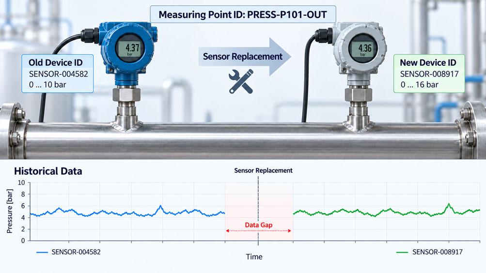
In an industrial production plant, the pressure in a process pipeline is continuously monitored. A pressure transmitter sends its measured value to the PLC. From there, the values are transferred through an edge gateway to a central historian, where they are stored for trend analysis, quality evaluations and long-term condition monitoring.
After several years, the pressure sensor is replaced due to a technical defect. The new transmitter has a different serial number, updated firmware and a larger configurable measuring range. The process connection remains unchanged, as do the function of the measuring point and its designation in the plant documentation.
After commissioning, the new sensor provides plausible measured values. The pressure indication in the control system returns to normal. Only several weeks later does a historical trend analysis reveal that the sensor replacement was not clearly documented.
The historian still contains a single time series with the original measuring point designation. However, it is no longer possible to determine which historical measurements came from the old sensor and which came from the new one. Furthermore, the new measuring span was initially not updated in the edge gateway.
The result is a dataset that appears complete at first glance but has limited technical significance.
This problem occurs when device identity, measuring point identity and data continuity are not clearly separated.
An industrial measuring point generally has a defined functional purpose that continues beyond the service life of an individual sensor. For example, the pressure upstream of a pump, the temperature of a reactor or the level in a vessel must be monitored.
The sensor used, however, is a replaceable physical asset. It may have a manufacturer serial number, its own device identifier, a measuring range, a firmware version and individual calibration information.
When the sensor is replaced, the permanent functional identity of the measuring point should be retained. At the same time, the point in time from which the new device is responsible for the measuring point must be documented.
This creates a time-dependent assignment: A particular sensor was installed at a particular measuring point during a defined period. After its removal, another sensor takes over the same measurement task.
This assignment is essential for long-term data analysis. Without it, subsequent differences between process changes, sensor deviations, measuring range adjustments and maintenance events cannot be reliably distinguished.
Such a situation becomes particularly critical when the new sensor has a different measuring range. If, for example, a 4-to-20-mA signal is interpreted using an outdated scaling configuration, measured values can be formally valid but physically incorrect.
There are also timing considerations. Measurement data may be missing during a sensor replacement. An edge gateway can buffer communication interruptions to some extent, but it cannot generate actual measurements while the physical sensor is out of service.
A complete data history therefore does not necessarily mean that a valid measured value must exist at every point in time. It is much more important that actual measurements, data gaps, invalid values and device replacements can be clearly distinguished.
Timestamps must also be handled correctly. A measured value may have been generated at the time of acquisition, processed later by the gateway and written to the historian significantly later. If these different times are confused, apparent process jumps or time shifts may appear in evaluations.
Modern IT/OT architectures also require a clear distinction between raw data, scaled process values, data quality indicators and configuration information.
Technologies such as OPC UA, Modbus, HART, IO-Link, MQTT and edge gateways provide different options for data transmission and device integration. However, they do not replace the need to define an unambiguous and permanently stable data model.
This technical article explains how measuring point IDs, device IDs, gateway IDs and historian tags can be distinguished. It covers time-valid sensor assignments, device replacement events, timestamps, data quality, scaling, buffering and secure data transmission.
A detailed calculation example considers a pressure measuring point where a sensor with a measuring range of 0 to 10 bar is replaced by a device with a range of 0 to 16 bar. It shows the effects of different scaling configurations, how many measurements are missing during a twelve-minute interruption and how historian data continuity can be evaluated correctly.
The article also covers practical data architecture, integration of existing installations, asset management systems, calibration information, IT/OT security and suitable IIoT sensors and integration solutions from ICS Schneider Messtechnik.
Table of Contents
- Measurement Task and Typical Problems During Sensor Replacement
- Distinguishing Measuring Point ID, Device ID and Other Identifiers
- Building a Suitable Data Model for Long-Term Measurement Data
- Time-Valid Assignment Between Sensor and Measuring Point
- Treating Sensor Replacement as a Documented Event
- Distinguishing Acquisition Time, Reception Time and Storage Time
- Handling Data Quality, Invalid Values and Measurement Gaps
- Practical Example: Calculating Sensor Replacement, Scaling and Data Gaps
- Separating Historian Tags from Physical Device Identity
- Versioning Measuring Ranges, Units and Scaling
- Edge Buffering, Data Backfill and Store-and-Forward
- Integrating OPC UA, MQTT, Modbus and HART Correctly
- Documenting Gateway Replacements and Communication Paths
- Asset Management, Serial Numbers and Calibration History
- Trend Analysis, Aggregation and Comparable Historical Data
- IT/OT Operations, Responsibilities and Change Management
- IT/OT Security, Access Control and Auditability
- Data Integrity, Measurement Uncertainty and Traceability
- Practical Architecture for Sensors, Edge and Historian
- Systematic Procedure for a Documented Sensor Replacement
- Typical Fault Symptoms and Targeted Diagnostics
- Suitable ICS Products and IIoT Integration Solutions
- Conclusion: Stable Measuring Point Identity and Traceable Device Replacements
- Frequently Asked Questions About Sensor Replacement in a Historian
1. Measurement Task and Typical Problems During Sensor Replacement
A historian stores measured values over periods that are often considerably longer than the service life of individual sensors.
The measuring instruments may be replaced several times while the process task and functional significance of the measuring point remain unchanged.
1.1 Historical Measurement Data as a Long-Term Asset
Measurement data is used, for example, for quality reports, process optimization, energy monitoring, maintenance planning and long-term comparative analyses.
Its significance depends not only on the measured numerical value but also on the associated measuring point and device information.
1.2 Typical Sensor Replacement
A sensor may be replaced for the following reasons:
- Technical defect.
- Scheduled maintenance.
- Calibration deviation.
- Mechanical damage.
- Need for a different measuring range.
- Improved measurement accuracy.
- New communication interface.
- Changed process conditions.
- Product discontinuation or successor model.
- Modernization of the automation system.
1.3 The Measurement Task Remains Unchanged
If the same physical process variable continues to be monitored at the same functional measuring point, the measuring point identity can be retained.
However, the newly installed physical sensor requires a new, unique device assignment.
1.4 Historian Tag Is Overwritten
In simple architectures, the data point is named directly after the address of a sensor or its current device identifier.
After replacement, this can create a new time series even though the measurement task remains unchanged.
Conversely, an existing time series may be continued without documenting the new sensor.
1.5 Lost Device History
If the previous device ID is overwritten by the new identifier, it is no longer possible to identify which device generated the older measured values.
As a result, maintenance and calibration information can no longer be clearly assigned to the historical data.
1.6 Apparent Data Continuity
A continuous line in a trend chart can give the impression that measurement continued without interruption during sensor replacement.
If missing values were interpolated or the last known value was carried forward unchanged, this representation is not equivalent to completely uninterrupted actual measurement.
1.7 Objective of Data Modeling
A suitable data model should be able to answer three questions at any time:
- Which physical measuring point was monitored?
- Which specific device generated a particular measured value?
- Under which temporal and technical conditions was the value recorded?
Separating this information provides the foundation for a traceable industrial measurement data history.
2. Distinguishing Measuring Point ID, Device ID and Other Identifiers
Different identifiers should not be mixed when managing industrial measurement data.
2.1 Measuring Point ID
The measuring point ID describes the permanently defined functional measurement task.
For example, it may identify a pressure measuring point at a particular pump or a temperature measuring point on a reactor.
Example:
PRESS-P101-OUT
In this example, the identifier describes the pressure measuring point at the outlet of pump P101.
2.2 Device ID
The device ID identifies the specific physical sensor or transmitter.
Example:
SENSOR-004582
After replacement, the new device is assigned the internal identifier SENSOR-008917, for example.
2.3 Serial Number
The serial number is frequently assigned by the manufacturer.
It can form part of the device identification, but it is not necessarily globally unique within a multi-manufacturer database without additional information.
For the data architecture, an internally unique device ID linked to the manufacturer and serial number is therefore useful.
2.4 Asset ID
An asset ID can identify equipment within a maintenance or asset management system.
Depending on the organizational model, it may refer to a physical device or a higher-level installation.
Its meaning must therefore be clearly defined.
2.5 Gateway ID
The gateway ID identifies the device that collects, processes or forwards sensor values.
Replacing a gateway does not automatically mean that a sensor has been replaced.
2.6 Communication Address
A Modbus address, IO-Link port number, HART address or OPC UA NodeId can be used for technical addressing.
However, such addresses are not necessarily permanent functional identities under all circumstances.
They may change during modifications or configuration changes.
2.7 Historian Tag
A historian tag is a logical data point in a time-series database.
In a suitably designed architecture, it should be linked to the functional measuring point ID.
The physical device assignment is managed separately.
2.8 Uniqueness
All identifiers used must be unique and consistently managed within their respective scopes.
For example, a suitable system prevents the same internal device ID from being unintentionally assigned to two different physical sensors at the same time.
3. Building a Suitable Data Model for Long-Term Measurement Data
An industrial data model should not consist exclusively of a timestamp and numerical value.
Additional information must be available for later use.
3.1 Measured Value
The measured value describes the recorded physical quantity.
For example:
5.20 bar
3.2 Unit
The unit must be clearly specified.
A value of 5.20 without a unit could describe pressure, temperature, voltage or another quantity.
3.3 Type of Physical Measurand
In addition to the unit, it must be known whether gauge pressure, absolute pressure or differential pressure is being measured, for example.
A device replacement involving different types of pressure must not silently be treated as an unchanged measurement series.
3.4 Timestamp
The measured value requires a traceable time reference.
A distinction must be made between when the measurement was generated and when the information arrived in the respective system.
3.5 Data Quality
A quality indicator documents, for example, whether a measured value is valid, uncertain or invalid.
The specific status definition depends on the communication and data model used.
3.6 Device Assignment
It must be possible to reconstruct the device ID that was valid at the time of measurement.
It can be stored directly in the data record or determined from a time-valid assignment.
3.7 Configuration Version
The scaling, measuring span and processing version that were valid at the time of acquisition must be known.
Otherwise, historical raw values may be interpreted incorrectly later.
3.8 Data Provenance
Data provenance describes whether a value comes directly from the sensor, was generated by a calculation, was entered manually or was subsequently corrected.
Such distinctions are particularly important for quality-related evaluations.
3.9 Data Model as a Foundation
A suitable minimum model can therefore include the following elements:
- Measuring point ID.
- Device ID or time-valid device assignment.
- Acquisition timestamp.
- Measured value.
- Physical unit.
- Type of measurand.
- Data quality status.
- Scaling or configuration version.
- Source and transmission path.
- Event and correction information, where applicable.
4. Time-Valid Assignment Between Sensor and Measuring Point
A central element of a reliable historian architecture is the historical assignment between the physical device and the measuring point.
4.1 Permanent Measuring Point Identity
The measuring point continues to exist as a functional entity as long as its intended measurement task and identity remain unchanged.
4.2 Time-Limited Device Assignment
Each physical device is assigned to a measuring point for a defined period.
This assignment ends after the device is removed.
4.3 Validity Start
The validity start describes the point in time from which the device is actually approved for the measuring point or, according to the defined system rules, may provide values.
It does not necessarily have to coincide with the time of mechanical installation.
4.4 Validity End
The validity end specifies when the respective device assignment ends.
Half-open intervals provide an unambiguous technical convention:
[valid_from, valid_to)
The start belongs to the validity interval, but the end does not.
4.5 No Unintended Overlap
If a measuring point has only one primary sensor at any given time, the corresponding active device assignments should not overlap.
For redundant or parallel measurement systems, the assignments must explicitly distinguish between primary, redundant and comparison data sources.
4.6 Retaining Historical Assignments
An old device assignment must not be replaced by a new one if doing so would destroy historical information.
Instead, the previous assignment is ended and a new assignment is created.
4.7 Example of an Assignment Register
| Property | Old Sensor | New Sensor |
|---|---|---|
| Measuring point ID | PRESS-P101-OUT | PRESS-P101-OUT |
| Internal device ID | SENSOR-004582 | SENSOR-008917 |
| Serial number | SN-A4582 (example) | SN-B8917 (example) |
| Measurand | Gauge pressure | Gauge pressure |
| Measuring range | 0 to 10 bar | 0 to 16 bar |
| Output signal | 4 to 20 mA | 4 to 20 mA |
| Configuration version | CFG-01 | CFG-02 |
| Validity start | Before replacement | 10:32:00 UTC |
| Validity end | 10:20:00 UTC | Open until the next replacement |
| Operating status | Removed | Active |
| Historian measuring point | PRESS-P101-OUT | PRESS-P101-OUT |
| Documentation event | Removal / decommissioning | Installation / approval |
The identifiers and timestamps in this table are hypothetical examples. They illustrate the data structure and do not represent product-specific requirements.
5. Treating Sensor Replacement as a Documented Event
A sensor replacement is not merely a mechanical maintenance operation but also a relevant data event.
5.1 Removal Event
When a sensor is removed, it should be documented which device was removed and at what time its valid measurement acquisition ended.
5.2 Installation Event
The installation event identifies the new physical sensor and its intended measuring point.
5.3 Technical Approval
Tests, parameter adjustments or calibration checks may be required after installation.
Approval for normal measurement operation should be traceable separately from mechanical installation.
5.4 Reason for Device Replacement
The reason for replacement can be relevant to later evaluations.
For example, replacement due to an unusual measurement deviation may be evaluated differently from a planned model upgrade.
5.5 Replacement Record
A suitable replacement record includes, among other things:
- Measuring point ID.
- Old device ID.
- New device ID.
- Removal timestamp.
- Installation timestamp.
- Approval timestamp.
- Reason for replacement.
- Old and new measuring ranges.
- Calibration or test status.
- Responsible person or approving process.
- Relevant configuration versions.
- Impact on data continuity.
5.6 Event in the Historian
The sensor replacement can be stored as an independent event and linked to the measuring point ID.
This allows it to be displayed in trend charts and reports later.
5.7 Auditability
Subsequent changes to the replacement event should remain traceable.
For demanding applications, a version-controlled or auditable event register may be necessary.
5.8 No Silent Data Modification
Previously stored historical values should not be overwritten without control simply because a new device has been installed.
Necessary corrections must be linked to their original data version and an appropriate change record.
6. Distinguishing Acquisition Time, Reception Time and Storage Time
An industrial measured value may receive multiple timestamps as it passes through the processing chain.
6.1 Acquisition Timestamp
The acquisition timestamp describes when the corresponding measurement was physically recorded or generated at the data source.
Depending on the sensor and protocol, this timestamp may come directly from the field device or only be generated when the PLC or gateway polls the value.
6.2 Reception Timestamp
The reception timestamp describes when the receiving system obtained the value.
This may be later than the actual measurement.
6.3 Storage Timestamp
The storage timestamp describes when the value was written to the historian.
For buffered or delayed data transmission, it may be significantly later than the acquisition timestamp.
6.4 OPC UA SourceTimestamp
OPC UA can provide a SourceTimestamp describing the time at which the value originated at the data source.
Its actual origin and accuracy depend on the respective system implementation.
6.5 OPC UA ServerTimestamp
The ServerTimestamp describes the temporal assignment made by the OPC UA server.
It must be distinguished from the SourceTimestamp.
6.6 Missing Source Timestamp
If a sensor only transmits a current value on request and has no acquisition timestamp of its own, the higher-level system must clearly define the time reference used.
A gateway timestamp must not be presented as the exact physical acquisition time without an appropriate basis.
6.7 UTC and Local Time
For historian data spanning multiple systems, storing unambiguous timestamps, for example in UTC, is advisable.
The local time zone can be taken into account for display purposes.
This avoids ambiguity during transitions between daylight saving time and standard time.
6.8 Time Synchronization
Sensors, PLCs, edge gateways and servers should use suitable time synchronization.
The required accuracy depends on the measurement task.
6.9 Subsequent Data Transmission
With store-and-forward, values must be delivered with their original appropriate time reference.
Otherwise, values recorded during a network interruption may incorrectly be shifted to the time when the connection was restored.
7. Handling Data Quality, Invalid Values and Measurement Gaps
A complete time series does not necessarily consist exclusively of valid process values.
Information about failures and uncertainties also belongs in the measurement data history.
7.1 Valid Measured Value
A valid value meets the quality requirements defined for the measuring point and system.
In OPC UA, corresponding information is provided through status codes, among other mechanisms.
7.2 Uncertain Measured Value
A value may be available even though its accuracy or validity is limited.
Examples include impaired sensor functions or certain configuration states.
7.3 Invalid Measured Value
An invalid measured value can result from communication failure, sensor malfunction or other errors.
It must not be used as a normal process measurement without appropriate identification.
7.4 No Measured Value
If no measurement takes place during sensor replacement, an actual measurement gap occurs.
This must be distinguished from a stored invalid value.
7.5 Last Valid Value
A system may continue displaying the most recently known valid value.
However, such a display must remain identifiable as stale or no longer current.
7.6 Interpolation
For certain statistical analyses, interpolation between available measurements may be useful.
However, interpolated values are calculated estimates rather than actual recorded measurements.
7.7 Simulation
During maintenance, a PLC may use a simulated or manually specified value under certain conditions.
Such a value must be identified accordingly in the data history.
7.8 Data Quality Model
An application-specific historian model should be able to distinguish at least between the following states:
- Valid.
- Uncertain.
- Invalid.
- Stale.
- No measurement available.
- Simulated or manually substituted.
- Delivered subsequently.
- Corrected subsequently.
These terms describe a possible application-specific model and should not be understood as an unchanged list of normative OPC UA status codes.
8. Practical Example: Calculating Sensor Replacement, Scaling and Data Gaps
A pressure measuring point on an industrial pump is recorded continuously.
The existing pressure sensor has a measuring range of 0 to 10 bar and provides an analog output signal of 4 to 20 mA.
Due to a defect, it is replaced by another pressure transmitter. The new device has a configured measuring range of 0 to 16 bar and also provides a 4-to-20-mA output.
The functional measuring point remains unchanged. However, the device ID must change and the scaling must be adjusted.
8.1 Initial Data and Assumptions
The following freely selected assumptions expressly apply to this calculation example:
- Measuring point ID: PRESS-P101-OUT.
- Old device ID: SENSOR-004582.
- New device ID: SENSOR-008917.
- Old measuring range: 0 to 10 bar.
- New measuring range: 0 to 16 bar.
- Output signal of both sensors: 4 to 20 mA.
- Sampling interval: 10 seconds.
- Observation period: 10:00:00 to 11:00:00 UTC.
- Last regular measurement from the old sensor: 10:19:50 UTC.
- End of the old device assignment: 10:20:00 UTC.
- Start of the new approved device assignment: 10:32:00 UTC.
- First regular measurement from the new sensor: 10:32:00 UTC.
- No valid physical measurements take place during the interruption.
- The time series uses a fixed ten-second grid.
- The scaling relationships are assumed to be ideally linear.
The values are for illustration only and do not represent real plant or manufacturer data.
8.2 Number of Expected Measurements
The observation period is one hour.
One hour contains:
3,600 seconds
At a measurement interval of 10 seconds, the expected number is:
N = 3,600 s / 10 s
N = 360 measurements
For this example, the timestamps from 10:00:00 inclusive to 11:00:00 exclusive are considered.
8.3 Measurements from the Old Sensor
The old sensor provides values from 10:00:00 through 10:19:50 UTC, inclusive.
The period is 20 minutes.
Nold = 20 · 60 / 10
Nold = 120 measurements
8.4 Interruption Caused by Sensor Replacement
No valid physical measurements take place between 10:20:00 and 10:32:00.
The interruption lasts:
12 minutes = 720 seconds
Therefore, the number of missing values is:
Nmissing = 720 / 10
Nmissing = 72 measurements
8.5 Measurements from the New Sensor
The new sensor provides valid values from 10:32:00 through 10:59:50 UTC, inclusive.
This period covers 28 minutes.
Nnew = 28 · 60 / 10
Nnew = 168 measurements
8.6 Measurements Actually Available
The number of genuinely recorded valid values is:
Nvalid = 120 + 168
Nvalid = 288 measurements
The remaining 72 expected timestamps have no valid physical measurement.
8.7 Data Availability
For this example, data availability is defined as the proportion of expected grid values for which valid measurements are actually available.
Availability = Nvalid / Nexpected · 100 %
Availability = 288 / 360 · 100 %
Availability = 80 %
Data availability during this particular hour is therefore 80 %.
This is an application-specific metric for the period being considered and not a universal definition of plant availability.
8.8 24-Hour Assessment
Assuming that only this single twelve-minute interruption occurs during a full day, the same ten-second grid produces:
Nday = 24 · 3,600 / 10
Nday = 8,640 measurements
Of these, 72 values are missing.
Nvalid,day = 8,640 – 72
Nvalid,day = 8,568 measurements
The calculated daily availability is:
8,568 / 8,640 · 100 %
Availability ≈ 99.17 %
This illustrates why data availability metrics should always specify their reference period.
8.9 Scaling of the Old Sensor
The old sensor has a measuring range of 0 to 10 bar.
The ideal linear assignment is:
p = (I – 4 mA) / 16 mA · 10 bar
At an assumed current of 12 mA:
pold = (12 – 4) / 16 · 10 bar
pold = 5.00 bar
8.10 Scaling of the New Sensor
The new sensor has a measuring range of 0 to 16 bar.
Its ideal linear assignment is:
p = (I – 4 mA) / 16 mA · 16 bar
At the same assumed current of 12 mA:
pnew = (12 – 4) / 16 · 16 bar
pnew = 8.00 bar
8.11 Error Caused by Retaining the Old Scaling
If the edge gateway continues using the old 0-to-10-bar measuring span after sensor replacement, it interprets the assumed 12 mA as 5.00 bar.
However, the new sensor assigns 8.00 bar to that current.
The absolute deviation is:
Δp = 8.00 – 5.00 bar
Δp = 3.00 bar
Relative to the correct value of 8.00 bar in this example:
ε = 3.00 / 8.00 · 100 %
ε = 37.5 %
In this scenario, the historian would store a formally available numerical value that is physically incorrect because of the wrong scaling.
8.12 Identical Current Signals Are Not Automatically Comparable
The two 12-mA examples are separate calculation cases.
They do not mean that the actual process pressure increased from 5 to 8 bar during sensor replacement.
Such a conclusion would require valid physical measurements and comparable process conditions.
8.13 Marking Sensor Replacement in the Trend
The historian contains three clearly distinguishable sections in this model:
- Until 10:19:50: Valid values from the old sensor.
- From 10:20:00 until before 10:32:00: No valid physical measurements.
- From 10:32:00 onward: Valid values from the new sensor after approval.
The device replacement event should be clearly visible in the trend.
8.14 Do Not Artificially Close the Measurement Gap
If the trend display directly connects the last value from the old sensor with the first value from the new sensor, it may falsely suggest continuous measurement.
The time series should therefore indicate the missing period accordingly.
8.15 Interpreting Store-and-Forward Correctly
Assume that the edge gateway can transmit locally stored values after a network interruption.
This function can recover data that was actually measured and stored locally during a communication outage.
However, it cannot generate the 72 measurements that were not taken at all during the physical sensor replacement.
8.16 Summary of Results
| Calculated Parameter | Assumption or Calculation | Result |
|---|---|---|
| Measuring point ID | Stable functional identifier | PRESS-P101-OUT |
| Old device ID | Example identifier | SENSOR-004582 |
| New device ID | Example identifier | SENSOR-008917 |
| Old measuring range | 4 to 20 mA | 0 to 10 bar |
| New measuring range | 4 to 20 mA | 0 to 16 bar |
| Sampling interval | Freely selected | 10 s |
| Observation period | 10:00 to 11:00 UTC | 60 min |
| Expected measurements | 3,600 / 10 | 360 |
| Old sensor measurements | 20 · 60 / 10 | 120 |
| Sensor replacement interruption | 10:20 to 10:32 UTC | 12 min |
| Missing measurements | 720 / 10 | 72 |
| New sensor measurements | 28 · 60 / 10 | 168 |
| Total valid measurements | 120 + 168 | 288 |
| Data availability during this hour | 288 / 360 · 100 % | 80 % |
| Data availability over 24 hours with one such interruption | 8,568 / 8,640 · 100 % | 99.17 % |
| 12 mA with old scaling | (12 – 4) / 16 · 10 | 5.00 bar |
| 12 mA with new scaling | (12 – 4) / 16 · 16 | 8.00 bar |
| Deviation caused by incorrect scaling | 8.00 – 5.00 | 3.00 bar |
| Relative deviation from the correct new value | 3.00 / 8.00 · 100 % | 37.5 % |
8.17 Effects on the Data History
In the example, sensor replacement does not create a new functional measuring point.
The measuring point ID therefore remains unchanged.
However, the device ID, measuring span and configuration version are reassigned.
The actual measurement gap remains visible in the historian.
8.18 Limitations of the Calculation Example
All device identifiers, measured values and timestamps are hypothetical.
The calculation assumes a regular ten-second grid and an ideally linear current-to-pressure characteristic.
Real systems may have different acquisition intervals, additional data quality states, measurement uncertainties, delays and other configuration models.
The calculation presented is not a mandatory system architecture but a comprehensible technical example.
9. Separating Historian Tags from Physical Device Identity
In an architecture designed for long-term data continuity, a historian tag should not exclusively reflect the identity of the sensor currently installed.
9.1 Functional Time-Series Reference
If a measuring point performs the same functional task across several generations of devices, a logical historian tag can represent this measuring point over the long term.
9.2 Sensor-Specific Data Channel
Individual device-specific data channels can also be managed.
These are relevant, for example, to device information, diagnostic values or technical comparisons.
9.3 Historian Tag During Sensor Replacement
During replacement, the physical device assignment is changed.
The functional time series does not have to be renamed or recreated solely because the sensor was replaced.
9.4 When a New Time Series Is Appropriate
If the functional meaning changes significantly, a new measuring point or time-series identity may be required.
This should be examined, for example, when changing from gauge pressure to absolute pressure or permanently relocating the measuring point to another process location.
9.5 Tag Alias
An additional alias structure can map historical and current technical names to a stable functional measuring point ID.
9.6 Data Queries
During a long-term historian query, measured values can be retrieved using the measuring point ID and assigned to the device and configuration version valid at the respective time.
9.7 Raw Data and Process Values
For demanding applications, it may be useful to store both suitable raw data and correctly scaled process values.
This allows subsequent verification of measuring range changes and scaling errors.
9.8 No Uncontrolled Data Mixing
A continuous functional time series is only meaningful if differences between device generations and measurement conditions remain identifiable.
10. Versioning Measuring Ranges, Units and Scaling
Sensor replacement can change the physical relationship between the raw signal and process value.
10.1 Analog Scaling
With a linear 4-to-20-mA signal, the electrical current is assigned to a defined physical measuring range.
10.2 Measuring Range Change
If the new sensor has a different measuring range, the corresponding scaling must be updated.
Otherwise, physically incorrect values may result.
10.3 Unit
A device can provide pressure values in bar, kPa or Pa, for example.
The target quantity in the historian must be clearly defined.
10.4 Conversion
Conversion between compatible units must be traceable and mathematically correct.
The original unit and conversion rule used should be documented.
10.5 Configuration Version
A new scaling configuration is assigned a new version identifier.
This is associated with an unambiguous validity start.
10.6 Historical Scaling
The previous scaling must be retained so that older raw values can continue to be interpreted correctly.
10.7 Measuring Range Limits
Underrange and overrange conditions must be handled according to the actual device functionality.
Incorrect scaling must not silently result in values that appear plausible but are actually wrong.
10.8 Related Technical Topic
The detailed versioning of raw values, units and scaling factors is covered in the related ICS technical article:
11. Edge Buffering, Data Backfill and Store-and-Forward
In industrial IIoT systems, the network connection between the field installation and the central historian may be interrupted temporarily.
11.1 Communication Failure
During a communication failure, the sensor and local controller may continue measuring normally even though there is no connection to the central historian.
11.2 Local Buffering
A suitable edge gateway can store measured values locally during the interruption.
Actual buffer capacity depends on the hardware, software and system configuration.
11.3 Store-and-Forward
After the connection is restored, locally stored measurements can be delivered subsequently.
The original appropriate measurement timestamps must be retained.
11.4 Physical Sensor Replacement
If no measurements take place during sensor replacement, no actual measured values can be buffered for that period.
A store-and-forward function therefore cannot replace missing physical data acquisition.
11.5 Duplicate Transmission
During retransmissions, messages or measurement records may arrive at the destination system multiple times.
Data processing must therefore use suitable mechanisms to prevent identical events from being counted multiple times unintentionally.
11.6 Idempotent Processing
A suitable procedure can identify each measurement record using a unique event identifier.
Alternatively, a clearly defined data model may use a combination of measuring point, timestamp and other unique sequence information.
The selected identifier must not accidentally merge distinct valid measurement events.
11.7 Sequence
Backfilled data may arrive later than current values that have already been stored.
The historian must therefore distinguish between event time and arrival order.
11.8 Buffer Overflow
If a communication interruption lasts longer than the available buffer capacity permits, measured values may be lost.
Such a condition should be detected and documented.
11.9 Device Replacement During an Interruption
If a sensor is replaced during a communication failure, older values delivered subsequently must still be assigned to the old device.
The later storage time must not result in these values being incorrectly assigned to the new sensor.
12. Integrating OPC UA, MQTT, Modbus and HART Correctly
Different industrial communication methods offer different functions for data transport and device integration.
12.1 Modbus RTU
Modbus RTU is frequently used to transmit measured values over RS-485.
Devices are addressed using the corresponding addresses and registers.
A Modbus address alone is not a permanently unique physical device identity.
12.2 HART
With suitable field devices, HART enables digital communication in addition to the analog 4-to-20-mA signal.
Depending on the device, identification and configuration information can be retrieved.
12.3 IO-Link
With suitable sensors, IO-Link enables transmission of process data as well as device and diagnostic information.
During device replacement, this information can be used for identification and parameterization.
12.4 OPC UA
OPC UA provides an industrial information and communication model.
Measured values can be transmitted with a data type, status code and timestamps.
12.5 OPC UA Status Codes
Status codes can describe valid, uncertain and faulty data states, among others.
Data quality information should not be discarded during historization without a deliberate decision.
12.6 MQTT
MQTT is a lightweight publish/subscribe messaging protocol.
The functional semantics of transmitted measurements must be defined by the data model or message format used.
12.7 Sparkplug
Sparkplug extends MQTT with defined structures for device and edge states and corresponding metric messages.
This can provide technical support for device replacements and state changes.
However, the long-term functional assignment to a measuring point ID must still be modeled appropriately.
12.8 Historical Messages
Historical measured values can be marked accordingly in protocols and data models designed for this purpose.
The receiving system must correctly assign these values in time.
12.9 No Automatic Data Continuity
None of the protocols mentioned guarantees on its own that a sensor replacement will be documented correctly in the historian from a functional perspective.
This requires unambiguous identities, assignment rules and a suitable system architecture.
12.10 Related Technical Article
The differences between communication methods are explained in the ICS technical article:
13. Documenting Gateway Replacements and Communication Paths
Not only sensors but also PLC modules, communication modules and edge gateways may be replaced during the operating life of an installation.
13.1 Gateway as an Independent Asset
The gateway has its own technical and, where applicable, physical identity.
It should therefore be managed independently of the connected measuring points.
13.2 Gateway Replacement
If a gateway is replaced, the existing sensors and measuring points may remain unchanged.
However, the technical communication assignment must be updated.
13.3 Driver Version
A new driver or updated gateway software can change data processing behavior.
Timestamps, scaling, diagnostic states and polling intervals are particularly relevant.
13.4 Register Mapping
In Modbus systems, register addresses, data types, byte order and scaling rules must be transferred correctly.
13.5 Topic Change
Changing an MQTT topic name does not automatically mean that a new functional measuring point has been created.
13.6 Communication Path
Technical data provenance can be described, for example, through the sensor, PLC, gateway and broker.
The valid version of this path can be stored for traceability.
13.7 Gateway Failure
A gateway failure can affect several measuring points simultaneously.
Data quality should correctly reflect this shared communication fault.
13.8 Migration Without Data Loss
During a planned gateway migration, the historical measuring point IDs and device assignments must be retained.
The migration must not create new functional measuring points without control.
14. Asset Management, Serial Numbers and Calibration History
The physical identity of a sensor is also important for maintenance, quality assurance and calibration.
14.1 Device Inventory
A device inventory contains information such as manufacturer, model, serial number, internal device ID and current installation location.
14.2 Device Replacement
During sensor replacement, the physical device assignment is updated.
The previous history remains linked to the removed device.
14.3 Calibration Information
The calibration date, calibration certificate and any identified measurement deviations can be relevant when evaluating historical data.
14.4 As-Found and As-Left
Certain calibration procedures distinguish between the condition before adjustment and the condition after adjustment.
This information can help evaluate the measurement quality of earlier periods.
14.5 Device Status
A device can be active, removed, under repair, calibrated or out of service, for example.
Its status should be managed in a traceable manner.
14.6 One Device at Multiple Measuring Points
A removed sensor can later be used at another measuring point, provided it is technically suitable.
In this case, its physical device ID remains unchanged, while a new time-valid measuring point assignment is created.
14.7 Multiple Sensors at One Measuring Point
Redundant measuring points may have several sensors installed simultaneously.
The assignment must then also account for their respective functions.
14.8 Asset Management System
A separate asset management or maintenance system can manage the device history.
The historian does not need to store all master data itself, but it should be able to link the relevant information unambiguously.
15. Trend Analysis, Aggregation and Comparable Historical Data
Sensor replacement can influence the interpretation of long-term measurement data.
15.1 Trend Continuity
A continuous time series is useful when the functional measurement task remains unchanged.
However, device replacement events must remain identifiable.
15.2 Sudden Measurement Change
A sudden difference after sensor replacement can have several causes.
These include an actual process change, differences in sensor measurement deviations or incorrect scaling.
15.3 Avoid Premature Interpretation
If different values are present before and after replacement, this alone does not establish a physical process change.
The measurement conditions must be sufficiently comparable for such a conclusion.
15.4 Mean Values
When calculating averages, it must be defined how data gaps and invalid values are handled.
Missing measurements must not automatically be interpreted as zero.
15.5 Minimum and Maximum
Minimum and maximum values can also be affected by data gaps.
A process peak that actually occurred during sensor replacement may no longer be reconstructable.
15.6 Data Availability
An availability metric should disclose the period under consideration and the definition of valid data.
For example, the metric may be based on expected grid values or on a time-weighted assessment.
15.7 Aggregation
During data aggregation, mean values, minimum values, maximum values and quality information can be stored.
The aggregation rules should be documented.
15.8 Event-Based Evaluation
The sensor replacement can appear as an event marker in reports.
This allows analyses before and after replacement to be performed separately or deliberately combined.
15.9 Long-Term Comparability
Measured values from different generations of devices are sufficiently comparable only if the measurand, unit, measuring range, measurement uncertainty and relevant process conditions are considered.
16. IT/OT Operations, Responsibilities and Change Management
Reliable sensor replacement requires not only a suitable technical data model but also a defined organizational procedure.
16.1 Maintenance Responsibilities
Maintenance typically manages physical installation, removal and functional testing of the sensor.
16.2 Automation Responsibilities
The automation team is frequently responsible for PLC configuration, measuring range, signal processing and technical device integration.
16.3 IT/OT System Administration Responsibilities
The team maintaining the historian and edge systems ensures that data assignment and transmission function according to the defined model.
16.4 Change Control
A sensor replacement should be treated as a traceable change.
This is particularly important when the measuring span, data processing or communication interface changes.
16.5 Four-Eyes Principle
For quality-critical measuring points, separate technical verification and approval may be appropriate.
The specific organizational implementation depends on the requirements of the installation.
16.6 Master Data Maintenance
Responsibility for maintaining device and measuring point master data must be clearly assigned.
Multiple independent and conflicting master data sources should be avoided.
16.7 Documentation Requirements
Test reports, configuration states and relevant approvals should be managed according to the quality and operating concept.
16.8 Periodic Review
Regular checks can identify incomplete device assignments, outdated scaling configurations or missing event entries.
17. IT/OT Security, Access Control and Auditability
Historian and edge systems form part of the industrial data infrastructure.
Their security must be considered when designing sensor replacement processes.
17.1 Access Control
Not every user should be able to change device assignments or scaling configurations at will.
Permissions should be assigned according to operational responsibilities.
17.2 Authentication
Changes to measuring point master data and configurations should be attributable to an authorized user or technical process.
17.3 Role Model
A role model may distinguish between read-only users, maintenance personnel, administrators and authorized approvers, for example.
17.4 Encrypted Transmission
TLS-secured connections, for example, can be used for suitable network connections.
The specific security architecture depends on the communication methods in use.
17.5 Network Segmentation
Separation of OT and IT network areas can form part of the security concept.
Gateways and data transmission paths must be managed accordingly.
17.6 Audit Logs
Relevant changes should be logged.
These include changes to measuring point assignments, scaling and user permissions, for example.
17.7 Historical Corrections
If historical data must be corrected, the original version should remain traceable.
Unnoticed overwriting makes subsequent verification more difficult.
17.8 Security Assessment
For industrial automation and control systems, the IEC 62443 series of standards may be relevant as a foundation for an appropriate IT/OT security assessment.
The specific implementation depends on the system, risks and organizational requirements.
17.9 Separation of Data and Safety Functions
A historian normally serves to record and analyze process data.
A historian evaluation does not automatically replace the independent, appropriately designed protective technology required for a safety-related function.
18. Data Integrity, Measurement Uncertainty and Traceability
The technical quality of long-term measurement data depends on several factors.
18.1 Sensor Measurement Uncertainty
Every sensor has specified measurement uncertainties or error limits.
These characteristics can change when a device is replaced.
18.2 Calibration History
Calibration history can help when evaluating measurement deviations retrospectively.
It must remain assigned to the device actually used.
18.3 Scaling Errors
Incorrect conversion of the raw signal can cause greater measurement deviations than the sensor itself.
18.4 Timestamp Errors
Incorrect or insufficiently synchronized timestamps can make it more difficult to assign process events correctly.
18.5 Data Loss
Missing measurements cannot subsequently be reconstructed as actual measurements unless another corresponding valid data source exists.
18.6 Historical Corrections
If incorrect scaling is identified and the necessary raw data is available, a documented recalculation may be possible.
However, mathematical correction does not replace evaluation of the original measurement uncertainty.
18.7 Proof of Data Origin
For a historical measured value, it may be necessary to determine which sensor, configuration and processing method were used.
18.8 Data Quality as Independent Information
A numerically plausible value may nevertheless be invalid due to sensor faults or incorrect assignment.
Data quality should therefore be managed independently of the numerical value.
18.9 Traceability
Linking measuring point ID, device ID, calibration information and valid configuration improves technical traceability.
18.10 Data Is Not Automatically Comparable
Even if both sensors measure the same process variable, their comparability must be examined for the respective evaluation.
Differences in installation, measuring range, dynamic response or accuracy may remain relevant.
19. Practical Architecture for Sensors, Edge and Historian
A suitable system architecture separates physical measurement acquisition, technical data transmission and long-term data management.
19.1 Field Level
The field level contains sensors, transmitters and, where applicable, local signal converters.
These record the actual process value.
19.2 PLC and Field Communication
The PLC or a field communication system integrates sensor values into the automation system.
19.3 Edge Gateway
The edge gateway can acquire, scale, timestamp and prepare values for transmission.
Depending on its configuration, it may also provide local buffering and diagnostic functions.
19.4 Message Transmission
Transmission to the historian or a higher-level platform can take place through MQTT, HTTPS or OPC UA, for example.
19.5 Historian
The historian provides long-term storage of measured values and associated time information.
The management of quality information and events must be compatible with the database used.
19.6 Measuring Point Register
A measuring point register manages the stable functional identities of measuring points.
19.7 Device Register
A separate register can manage physical devices, including manufacturer, serial number and configuration.
19.8 Assignment Register
The assignment register links devices and measuring points through time-valid relationships.
This allows the physical data source for a historical value to be determined.
19.9 Event Register
Maintenance, sensor replacement, calibration, approvals and relevant configuration changes are documented as events.
19.10 Evaluation Layer
Dashboards, reports and analytical applications access measured values together with their associated identities and quality information.
19.11 Example of a Data Chain
A corresponding architecture can be structured as follows:
Sensor → PLC / Field Communication → Edge Gateway → Secure Data Transmission → Historian → Dashboard / Reporting
In parallel, the data is linked to the measuring point, device and event registers.
19.12 No Single Rigid Architecture
The exact implementation depends on the products and systems used.
A small test bench does not necessarily require the same infrastructure as a large production plant.
However, separating the functional measuring point from the physical device remains useful.
20. Systematic Procedure for a Documented Sensor Replacement
Sensor replacement should be performed and documented according to a defined procedure.
The following steps describe a possible technical workflow for an industrial IIoT measuring point.
- Identify the measuring point: Clearly establish the existing stable measuring point ID.
- Identify the old device: Record device ID, serial number, measuring range and relevant configuration.
- Check the historian assignment: Determine which functional time series represents the measuring point.
- Document the reason for replacement: Record the defect, maintenance, modernization or other reason.
- Select the new device: Check measurand, measuring range, accuracy and process conditions.
- Check communication compatibility: Determine the output signal and required protocols.
- Verify calibration status: Record suitable test or calibration information for the new device.
- Plan configuration changes: Document measuring span, unit, filters and alarm parameters where applicable.
- Perform safe decommissioning: Implement the required operational and technical protective measures.
- Preserve the last valid measured value: Document the timestamp and data quality of the last regular measurement.
- End the old device assignment: Close the validity period of the previous sensor.
- Replace the physical device: Perform installation according to the intended installation and safety conditions.
- Record the new device ID: Create or assign the new sensor unambiguously in the device register.
- Activate the new configuration: Set the measuring range and processing according to the specifications.
- Check the communication path: Verify the PLC, gateway and historian connections.
- Verify timestamps: Correctly assign acquisition and reception time references.
- Check data quality: Correctly capture fault, maintenance and invalid states.
- Perform functional testing: Check the plausibility of the measured value, scaling and, where applicable, reference measurement.
- Document approval: Establish the start of regular data acquisition by the new sensor.
- Activate the new device assignment: Link the measuring point ID to the new device ID and validity period.
- Check the historian trend: Verify the correct assignment of old and new values.
- Mark the measurement gap: Document the period without valid physical measurements.
- Verify data backfill: Import buffered values where applicable without duplicate storage.
- Check trends and reports: Verify the display of the sensor replacement event and data continuity.
- Complete the change: Document master data, configuration versions, test results and responsible personnel.
Additional approvals and tests may be required for safety-critical or quality-critical measuring points.
21. Typical Fault Symptoms and Targeted Diagnostics
Errors following sensor replacement can occur at the field level, during scaling, in communication or in the historian.
| Fault Symptom | Possible Cause | Suitable Diagnostic Action |
|---|---|---|
| Historical values cannot be assigned to a physical sensor | Device ID was overwritten or not historically recorded | Check the device register and time-valid assignments |
| A new historian tag is unintentionally created after sensor replacement | Tag name is directly linked to the technical device address | Separate functional measuring point ID from technical addressing |
| Measured values are significantly too low after replacement | New measuring span not taken into account during scaling | Check 4-to-20-mA assignment and configuration version |
| Measured values are significantly too high after replacement | Incorrect measuring range or unit | Compare raw signal, scaling and unit |
| Trend shows no interruption despite physical sensor replacement | Interpolation or continuation of the last measured value | Investigate data quality indicators and actual acquisition timestamps |
| Multiple values have the timestamp of reconnection | Storage time used instead of original measurement time | Check source, reception and storage timestamps |
| Values are missing after a communication failure | No buffering or buffer overflow | Investigate the edge buffer and data backfill mechanism |
| Duplicate measurements appear after reconnection | Repeated transmission without suitable duplicate detection | Check event identifiers and idempotent processing |
| Old buffered values are assigned to the new sensor | Device assignment based on storage time instead of event time | Correct the time-valid device assignment |
| Historical value appears plausible but is technically invalid | Data quality status was not transferred | Check field device and OPC UA status information |
| Measuring point is assigned to two sensors simultaneously | Overlapping assignment intervals or unclear redundancy role | Check validity intervals and role model |
| Sensor replacement event is missing from the trend | Maintenance event not linked to the measuring point ID | Check the event register and historian link |
| Several measuring points are unavailable after gateway replacement | Incorrect technical addressing or mapping | Check gateway configuration, registers and communication path |
| Measured values from different device generations are not comparable | Different measuring ranges, measurands or calibration states | Evaluate device history and metrological characteristics |
| Historical measured values change unnoticed after a data correction | Missing version control and change logging | Check data correction procedures and audit logs |
The causes listed are possible diagnostic approaches and do not constitute definitive fault identification.
For quality-related or safety-related data, necessary corrections must be performed according to the intended change and approval process.
22. Suitable ICS Products and IIoT Integration Solutions
ICS Schneider Messtechnik offers various IIoT solutions, industrial sensors, transmitters and data loggers for integrating measuring points into higher-level IT/OT systems.
For the sensor replacement described here, the function of the field device alone is not decisive. It is also important how its identity and configuration are transferred to the higher-level data model.
22.1 ICS IIoT Solutions – Integration from Field Device to Cloud
The IIoT solutions from ICS Schneider Messtechnik connect industrial sensors, actuators and controllers with edge gateways and higher-level data and automation systems.
The services and technical capabilities described include:
- Manufacturer-independent integration of industrial sensors.
- Connection via RS-485 and Modbus RTU.
- Integration of suitable HART devices.
- Integration of IO-Link sensors.
- Support for suitable OPC UA and Ethernet connections.
- Transmission of measurement data via MQTT or HTTPS.
- Integration into SCADA and cloud systems.
- Edge-based preprocessing and scaling.
- Timestamping of measured values.
- Local alarm and diagnostic functions.
- Suitable communication solutions using TLS or VPN.
- Register mapping and data modeling.
- Support with topic design and commissioning.
- Documentation of the implemented solution.
These services provide a suitable basis for implementing a measuring point architecture that remains traceable over the long term.
However, the specific management of device replacement events, historical assignments and data quality information must form part of the respective project requirements.
The general IIoT capabilities of a solution do not automatically mean that every historian system already includes a complete sensor replacement register.
Further Information: IIoT Solutions at ICS Schneider Messtechnik
22.2 ICS IIoT Pressure Monitoring – Pressure Sensors and Edge Connectivity
ICS IIoT pressure monitoring enables suitable pressure and differential pressure sensors to be integrated into industrial IT/OT architectures.
Different field interfaces and communication methods can be used depending on the configuration and project.
Features described include:
- Integration of industrial pressure transmitters.
- Connection via Modbus RTU.
- HART integration for suitable devices.
- IO-Link-based data connectivity.
- Edge gateways for measurement data acquisition.
- Measured value scaling and time assignment.
- Transmission via MQTT or HTTPS.
- Local and higher-level alarms.
- Dashboards and reporting.
- Measurement data traceability.
- Suitable security mechanisms such as TLS and VPN.
- Integration into new and existing installations.
This architecture is particularly interesting when existing pressure sensors need to be replaced or modernized without losing their long-term functional measuring point identity.
The stable measuring point ID and time-valid physical device assignment must be included in the data model for this purpose.
Further Information: IIoT Pressure Monitoring at ICS Schneider Messtechnik
22.3 Siemens SITRANS P320 – Digital Pressure Transmitter with HART
The Siemens SITRANS P320 is a digital process transmitter for industrial pressure measurement applications.
It is available in different configurations for gauge pressure, absolute pressure, differential pressure and other process-related measurement tasks.
Documented features include:
- Industrial digital pressure transmitter.
- HART communication.
- Analog measurement transmission using 4 to 20 mA.
- Different pressure measuring ranges and measuring cells.
- High measurement accuracy in suitable configurations.
- Digital diagnostic functions.
- Diagnostic information according to NAMUR NE107.
- Local parameterization.
- Parameterization using suitable HART tools.
- Different material and process connection variants.
- Suitable configurations for demanding industrial processes.
During sensor replacement, the HART interface can be useful for retrieving corresponding device information and configuration parameters.
Which identification data is actually available depends on the specific configuration and integration used.
However, the P320 does not replace the historian data model required for long-term device assignment.
Further Information: Siemens SITRANS P320 at ICS Schneider Messtechnik
22.4 Siemens SITRANS TH320 – Temperature Transmitter with HART
The Siemens SITRANS TH320 is a temperature transmitter for industrial applications.
Among other applications, it is installed in the connection head of suitable temperature sensors.
Documented features include:
- Temperature transmitter for head mounting.
- Universal input for suitable temperature and other sensor signals.
- Connection of resistance thermometers.
- Connection of thermocouples.
- Galvanically isolated two-wire output.
- 4-to-20-mA output with HART communication.
- Input monitoring for wire breakage and short circuits.
- Internal diagnostic functions.
- Storage of configuration settings in EEPROM.
- Advanced diagnostic functions in suitable configurations.
For a temperature-related historian measuring point, replacement of the transmitter can be documented separately from replacement of the actual temperature sensor.
This distinction is important when several physical components together form a measurement chain.
The measuring point ID can continue to describe the same temperature measurement task while the identifier of the transmitter or sensor changes.
Further Information: Siemens SITRANS TH320 at ICS Schneider Messtechnik
22.5 WIKA NETRIS®3 – LoRaWAN Radio Unit for Industrial Measuring Instruments
The WIKA NETRIS®3 is an IIoT-enabled radio unit for transmitting measurement data from suitable WIKA devices.
It is intended for corresponding industrial remote monitoring tasks and suitable hazardous areas.
Documented features include:
- LoRaWAN-based wireless transmission.
- Battery-powered radio unit.
- Digital acquisition of data from suitable WIKA measuring instruments.
- Transmission of configurable data packets.
- Integration into suitable IIoT applications.
- Web-based remote monitoring through the corresponding system architecture.
- Suitable communication security mechanisms.
- Configurations for hazardous areas.
- Suitable connections to compatible WIKA measuring instruments.
In wireless IIoT architectures, the physical identity of the sensor and the identity of the radio unit must be considered separately if they are independently replaceable components.
Replacing a radio module does not necessarily mean that the actual measuring point or physical measuring sensor has been changed.
The precise representation in the historian must match the device and network architecture used.
Further Information: WIKA NETRIS®3 at ICS Schneider Messtechnik
22.6 ICS IIoT Temperature Monitoring
ICS IIoT temperature monitoring integrates suitable temperature sensors and transmitters into higher-level data and monitoring systems.
Depending on the solution, the following technologies may be relevant:
- Resistance thermometers and thermocouples.
- Digital temperature transmitters.
- HART communication.
- Modbus or RS-485.
- IO-Link.
- Edge gateways.
- MQTT and HTTPS.
- Dashboard and alarm functions.
- Historical measurement recording.
For long-term temperature data, it is particularly important to establish whether only the sensing element, the head transmitter or the complete measurement chain has been replaced.
Each of these changes can have different effects on measurement data and the associated device history.
Further Information: IIoT Temperature Monitoring at ICS Schneider Messtechnik
22.7 ICS IIoT Level Monitoring
ICS IIoT level monitoring enables suitable level measuring instruments and level switches to be integrated into industrial data architectures.
Different measuring principles and communication interfaces are used depending on the application.
The integration options described include:
- Hydrostatic level measurement.
- Radar-based measuring systems.
- Ultrasonic measurement.
- Differential-pressure-based level measurement.
- Suitable level switches.
- Modbus and HART connectivity.
- IO-Link integration.
- Edge-based data acquisition.
- Transmission via MQTT or HTTPS.
- Dashboards, alarms and reporting.
When changing between different level measurement principles, it is particularly important to verify whether the functional measurand, reference height and scaling remain unchanged.
Otherwise, historical values may have the same unit but may not be directly comparable from a technical perspective.
Further Information: IIoT Level Monitoring at ICS Schneider Messtechnik
22.8 Data Loggers and Universal Measuring Instruments
ICS also offers various data loggers and universal measuring instruments for recording physical and electrical quantities.
Depending on the instrument, pressure, temperature, humidity, voltage or current can be recorded, for example.
The following characteristics are particularly relevant for long-term data continuity:
- Available data storage.
- Timestamps and time synchronization.
- Measurement channel identification.
- Device and configuration information.
- Export and interface functions.
- Storage capacity.
- Measurement interval.
- Documented data quality.
- Compatibility with the intended evaluation software.
Whether a specific instrument supports automated historian integration must be verified using its interfaces and software functions.
Further Information: Data Loggers and Universal Measuring Instruments at ICS Schneider Messtechnik
22.9 Technical Selection of an IIoT Measuring Point with Long-Term Traceability
At least the following information should be recorded for an IIoT project involving long-term historian data storage:
- Physical measurement task.
- Permanent measuring point ID.
- Type of measurand and unit.
- Sensor types used.
- Physical device identification.
- Available serial numbers and digital identification data.
- Measuring range and measurement uncertainty.
- Field interface used.
- Acquisition and transmission intervals.
- Required timestamp and its accuracy.
- Data quality information.
- Edge gateway and data transmission.
- Historian or cloud system.
- Assignment model between sensor and measuring point.
- Scaling version control.
- Handling of communication failures.
- Local buffering and data backfill.
- Duplicate detection.
- Maintenance and calibration events.
- IT/OT security requirements.
- Access and change permissions.
- Required documentation and auditability.
Based on this information, an architecture can be developed in which physical sensors can be replaced without losing the functional identity of their measuring points or the traceability of historical data.
IIoT Measurement Technology and System Integration at ICS Schneider Messtechnik
23. Conclusion: Stable Measuring Point Identity and Traceable Device Replacements
Industrial measurement data is frequently stored and evaluated over many years.
During this period, the sensors, transmitters, gateways and automation systems used may be replaced or modernized several times.
To keep the historical database meaningful, the identities of the measuring point and physical devices must be managed separately.
The measuring point ID describes the permanently defined functional measurement task.
The device ID, by contrast, identifies the specific sensor or transmitter.
When a sensor is replaced, the measuring point ID can remain unchanged while the device ID changes.
A documented time-based assignment between these two identities is essential.
This makes it possible to determine later which device generated a historical measured value.
Calibration information, measuring range, firmware, diagnostic status and maintenance events can also be assigned to the corresponding device generation.
Sensor replacement should therefore be documented as a separate event.
This event includes not only removal of the old sensor and installation of the new one, but also technical approval and the relevant configuration.
Correct scaling is particularly important.
When a pressure sensor with a measuring range of 0 to 10 bar is replaced by a sensor with a range of 0 to 16 bar, the assignment of its 4-to-20-mA signal must be updated accordingly.
The calculation example shows that the same 12 mA corresponds to 5.00 bar with the old scaling and 8.00 bar with the new scaling.
Accidentally retaining the old scaling can therefore lead to considerable errors even though the transmitted current signal is electrically correct.
The new scaling should receive its own configuration version.
The previous version must be retained so that older measurements can continue to be interpreted correctly.
Temporal data continuity is also essential.
A physical sensor replacement can result in an actual interruption in measurement.
In the calculation example, 72 valid measurements are missing during a twelve-minute interruption with a ten-second sampling interval.
Only 288 of the 360 expected values are therefore available within one hour. The calculated data availability is 80 %.
Such an interruption must remain identifiable in the historian.
Artificially connecting the last old measurement to the first new one, on the other hand, can give a misleading impression of continuous data acquisition.
Suitable edge gateways can bridge communication interruptions through local buffering and subsequent data transmission.
However, this works only for values that were actually acquired.
Actual measurements cannot be generated retrospectively for a period during which the physical sensor was not measuring.
When data is delivered subsequently, its original timestamps and device assignments must also be retained.
Otherwise, older values may be incorrectly assigned to the new device or to the time of reconnection.
Communication methods such as OPC UA, MQTT, Modbus, HART and IO-Link offer different options for integrating industrial measuring instruments.
OPC UA, for example, enables the transmission of quality status and timestamps.
MQTT and corresponding data models can be used for efficient transmission of measured values and device states.
However, actual functional data continuity does not arise solely from the choice of communication protocol.
It must be ensured through a deliberately defined data architecture.
This includes a stable measuring point register, a historically maintained device register, unambiguous assignment rules and traceable change management.
Data quality must also be treated as independent information.
A valid process value, an invalid measured value, a stale value and an actual measurement gap have different meanings.
These distinctions are relevant to long-term trends, quality assurance and fault diagnostics.
With its IIoT solutions, ICS Schneider Messtechnik provides a suitable foundation for integrating various industrial sensors into edge, SCADA and cloud architectures.
The specific implementation of long-term historical device assignments must be included in the respective project design.
For long-term data quality, it is not enough for the new sensor to deliver plausible numerical values after replacement.
What matters is whether, even years later, it remains possible to identify which device, with which configuration, generated the respective data at what time.
The key conclusion is: When replacing a sensor in a historian, the functional measuring point ID must be managed independently of the physical device ID. Device replacements, configuration changes and measurement gaps must remain unambiguously documented over time. Only stable identities, historical assignments, correct timestamps, data quality indicators and traceable scaling configurations provide reliable long-term data continuity.
24. Frequently Asked Questions About Sensor Replacement in a Historian
24.1 What Happens to Historical Measurements When a Sensor Is Replaced?
Historical measurements should be retained. If the new sensor takes over the same functional measurement task, the existing measuring point ID can continue to be used. However, the physical device ID must be updated and the time-valid device assignment documented. This ensures that the device responsible for each historical measurement remains identifiable.
24.2 What Is the Difference Between Device ID and Measuring Point ID?
The measuring point ID describes the functional measurement task, such as the pressure at the outlet of a particular pump. The device ID identifies the physical sensor actually being used. A sensor can be replaced without changing the measurement task. Both identities should therefore be managed separately.
24.3 Must a New Historian Tag Be Created After Sensor Replacement?
Not automatically. If the same physical quantity continues to be measured at the same functional measuring point, the existing logical time series can be continued. However, sensor replacement must be documented as an event. A significant change in the measurement task may require a new functional time-series identity.
24.4 Why Should the Device ID Not Simply Be Used as the Historian Tag?
A device ID identifies a replaceable sensor. If it is used directly as the permanent time-series identifier, every sensor replacement may create a new historical data series. A stable measuring point ID is frequently more appropriate for long-term process analysis. The device ID is then linked to the measuring point through time-valid assignments.
24.5 How Should the Time of Sensor Replacement Be Documented Correctly?
Ideally, removal time, installation time and technical approval time are documented separately. The old device assignment ends at a defined point in time. The new assignment begins as soon as the new device is permitted to provide regular valid measurements according to the agreed procedure. The timestamps used should be unambiguous and comparable across systems.
24.6 What Happens to a Measurement Gap During Sensor Replacement?
An actual measurement gap should remain identifiable in the historian. If no physical measurements were taken during replacement, they cannot later be reconstructed as actual measurements. Estimated values may be used for certain evaluations, but they must be clearly distinguishable from genuinely measured data.
24.7 Can an Edge Gateway Recover Missing Measurements After Sensor Replacement?
An edge gateway can deliver data that was actually measured and stored locally during a communication interruption. However, it cannot generate actual measurements if the sensor was completely out of service during replacement. A distinction must therefore be made between a network interruption and a physical measurement interruption.
24.8 Why Can Incorrect Values Appear in the Historian After Sensor Replacement?
A common cause is scaling that has not been updated. For example, a new 4-to-20-mA pressure sensor with a different measuring span represents a different physical value at the same current. If the gateway or PLC continues using the old scaling, incorrect process values result. Units, signal types and filter settings must also be checked.
24.9 How Are Different Sensor Measuring Ranges Managed Historically?
Each relevant scaling configuration should be documented with its own configuration version and temporal validity range. This allows historical raw values to be interpreted using the correct assignment. A new measuring span must not be applied without control to older values that were acquired under a different configuration.
24.10 Which Timestamps Should a Historian Store?
For demanding applications, the time at which the measurement was acquired is particularly important. Reception and storage timestamps may also be relevant. OPC UA provides SourceTimestamp and ServerTimestamp, among others. Their actual meaning and accuracy must be known for the system concerned.
24.11 What Does Data Quality Mean in a Historian?
Data quality describes whether a measured value is valid, uncertain or invalid, for example. Additional application-specific states can identify stale, simulated or subsequently corrected values. This information is important because a numerically plausible value is not necessarily technically valid.
24.12 How Can Duplicate Measurements Be Avoided After a Communication Interruption?
The data model should provide suitable unique identification of measurement events. This allows previously stored events to be recognized during repeated transmission. Processing should be designed so that repeated delivery does not create unintended duplicates. Legitimately distinct measurement events must still remain separate.
24.13 What Is the Difference Between Device Replacement and Gateway Replacement?
During device replacement, the physical sensor or transmitter is replaced. During gateway replacement, a component of the communication or processing path is exchanged. The sensor and functional measuring point may remain unchanged. Sensor, gateway and measuring point identities should therefore be documented separately.
24.14 Can the Same Sensor Later Be Used at Another Measuring Point?
Yes, provided it is technically suitable for the new application. The physical device ID remains unchanged. The previous measuring point assignment is ended and a new time-valid assignment is created. This allows device history to be traced across different installation locations without losing historical measuring point information.
24.15 What Role Does Calibration History Play During Sensor Replacement?
Calibration history documents important characteristics and possible measurement deviations of the physical device. It should therefore remain linked to the respective device ID. During subsequent data analysis, it can then be determined which sensor, with which calibration status, was used at a particular time.
24.16 Can OPC UA or MQTT Automatically Document Sensor Replacement?
Both technologies can transmit corresponding technical information but serve different purposes. OPC UA supports structured data models, status codes and timestamps. MQTT can transmit measurements and events; Sparkplug adds defined device and state structures. Long-term functional historization of sensor replacement must nevertheless be implemented appropriately.
24.17 How Should Sensor Replacement Be Displayed in Trend Analysis?
Ideally, replacement should be visible as a separate event marker. Historical values are retained, while an actual measurement gap is not concealed by an apparently continuous measurement line. If required, additional information about the old and new devices, measuring span, configuration version and calibration status can be displayed.
24.18 Which ICS Solutions Are Suitable for Long-Term Historian Measurement Data?
ICS Schneider Messtechnik offers IIoT solutions for integrating suitable industrial sensors through field interfaces, edge gateways and higher-level IT/OT systems. These include pressure, temperature and level monitoring as well as suitable HART, Modbus, IO-Link and MQTT integrations. For a long-term traceable historian architecture, stable measuring point IDs, historical device assignments, timestamps, data quality and version control must be explicitly included in the respective system solution.