


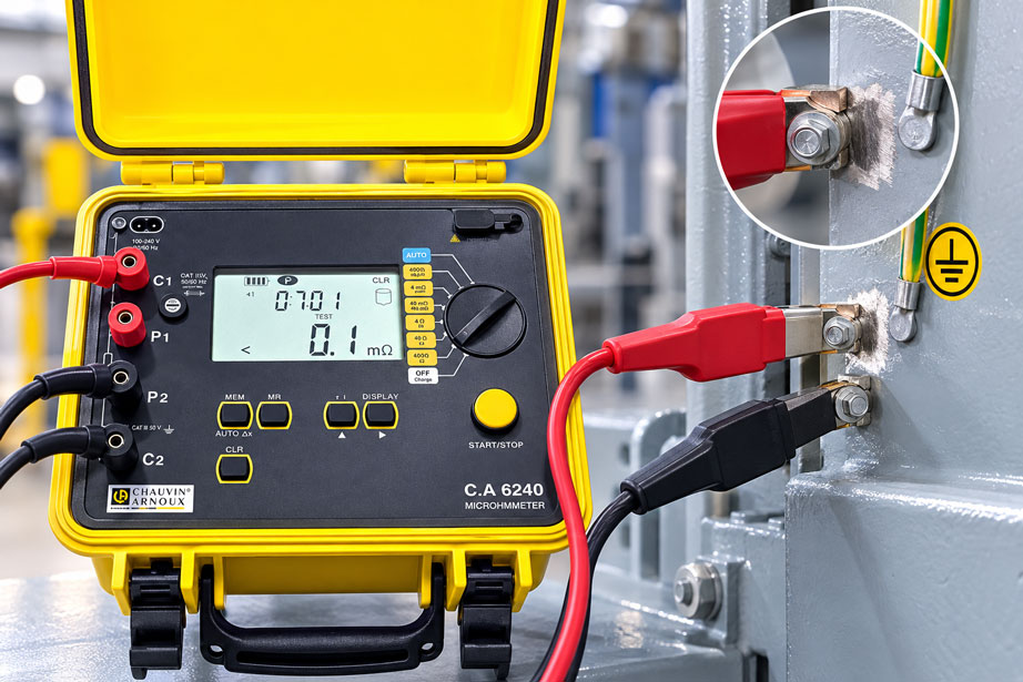
During the electrical safety inspection of an industrial machine, the protective earth connection between the central PE terminal and a painted control cabinet housing must be tested. A green-yellow protective conductor is visibly attached to a screw connection on the housing. The screw is firmly tightened, the cable routing is undamaged, and the rest of the electrical installation initially shows no abnormalities.
However, an unusual behavior becomes apparent during continuity testing with a low-resistance tester. When the test probe is placed on the painted housing surface, the resistance is very high or the instrument does not indicate sufficient continuity. When the test probe is pressed more firmly against a metallic edge, the indicated resistance decreases significantly.
When the measurement is repeated on the bare metal surface of a screw head, the connection suddenly appears to have a low resistance. The person performing the test must now determine whether a reliable protective earth connection actually exists or whether the test probe has merely established a favorable electrical contact.
This distinction is essential for the electrical safety of machines, control cabinets and industrial electrical equipment.
A protective earth connection is intended to ensure that all designated accessible conductive parts are connected to the protective earthing system. In the event of an electrical insulation fault, a suitable fault current path must be available so that the intended protective measure can operate effectively.
However, the mere presence of a green-yellow conductor does not prove that the electrical connection has a sufficiently low resistance over the long term. Particularly with painted, powder-coated, anodized or corrosion-protected components, electrical contact can be impaired by insulating surface layers.
A common mistake is to evaluate electrical conductivity solely through the contact between the test probe and the component. If a sharp test probe penetrates the paint layer and reaches the underlying metal, the indicated resistance can be very low. However, this does not automatically prove that the actual protective earth connection has a permanently suitable metallic contact.
Conversely, a high measured resistance on an intact painted surface can occur even though the component is correctly connected to the protective equipotential bonding system through a separate, specifically designed contact point.
For a meaningful test, the intended protective conductor current path and the actual existing contact points must therefore first be identified.
The test current also plays an important role. Many continuity tests use suitable instruments with a test current of at least 200 mA. For certain machine inspections, higher test currents up to approximately 10 A may also be relevant, provided that the applicable standard, test procedure and characteristics of the equipment under test permit their use.
However, a higher test current does not automatically mean a better or safer test. At a faulty connection, an excessively high current can cause considerable local power dissipation. In addition, the test must not damage sensitive components or drive impermissible currents through unsuitable paths.
When measuring very low resistances, the choice of measurement method becomes particularly important. Conventional two-wire measurement includes the resistance of the device under test as well as contributions from test leads and test contacts. In four-wire measurement using the Kelvin principle, the voltage drop is measured using separate leads, which can significantly reduce these influences.
However, four-wire measurement is not automatically proof of a reliable protective earth connection either. It measures the resistance between the selected voltage sensing points. If the electrical connection is bypassed by an alternative current path or the test contacts are positioned incorrectly, even a highly accurate instrument can produce a misleading result.
For evaluation, the test procedure, contact point, current path, test current, conductor length, conductor cross-section, mechanical condition and any existing parallel connections must therefore be considered together.
This technical article explains low-resistance testing of protective earth and protective equipotential bonding connections on painted machine and control cabinet components. It describes correct electrical contact, the interaction between paint layers and metallic connections, the selection of suitable test currents and the differences between two-wire and four-wire measurement.
A detailed calculation example shows the expected conductor resistance for a defined copper conductor, how contact resistances affect the result and how different test currents influence voltage drop and electrical power dissipation.
Possible parallel paths, common misinterpretations, evaluation of measurement uncertainty, test documentation, relevant standards and suitable low-resistance testers from the ICS Schneider Messtechnik product range are also covered.
Table of Contents
- Measurement Task and Typical Problems with Painted Components
- Distinguishing Protective Earthing and Protective Equipotential Bonding
- Paint Layers, Coatings and Electrical Contact
- Ensuring Suitable Protective Earth Contact Points Through Proper Design
- Comparing Two-Wire and Four-Wire Low-Resistance Measurement
- Selecting Test Current and Test Voltage According to the Test Task
- Correctly Defining Measurement Points, Test Probes and Electrical Current Paths
- Practical Example: Calculating Conductor Resistance, Contact Faults and Test Current
- Evaluating Contact Resistance and Mechanical Contact Quality
- Identifying Parallel Protective Earth Paths and Misleading Low-Resistance Readings
- Test Lead Resistance, Lead Compensation and Contact Errors
- Current Direction, Thermoelectric Voltages and Measurement Stability
- Inspecting Screw Connections, Contact Washers and Corrosion Protection
- Control Cabinet Doors, Machine Covers and Moving Components
- Selecting Continuity Testers, Installation Testers and Micro-Ohmmeters
- Correctly Evaluating Limits and Permissible Protective Earth Resistance
- Calibration, Self-Checks and Functional Verification of Test Instruments
- Measurement Uncertainty and Repeatability at Low Resistances
- Electrical Safety and Relevant Standards
- Systematic Testing and Commissioning Procedure
- Typical Fault Symptoms and Targeted Diagnostics
- Suitable ICS Products for Protective Earth and Low-Resistance Testing
- Conclusion: Permanent Contact Quality Matters More Than a Single Measurement
- Frequently Asked Questions About Protective Earth Connections on Painted Components
1. Measurement Task and Typical Problems with Painted Components
A protective earth test is intended to determine whether the relevant conductive parts of electrical equipment are connected through a suitable protective earth or protective equipotential bonding path.
Painted components can present particular design-related and metrological challenges.
1.1 Typical Applications
Low-resistance testing of such connections is relevant, for example, to the following installations and components:
- Machine housings and machine frames.
- Electrical control cabinets.
- Control cabinet doors and mounting plates.
- Metal machine enclosures.
- Removable protective covers.
- Motors and electrical drive units.
- Metal housings for operating controls.
- Protective equipotential bonding connections.
- Conductive cable support systems, where appropriately integrated into the protective system.
- Industrial electrical equipment after repair or modification.
1.2 Visibly Connected Protective Conductor
A visibly attached protective conductor initially indicates that an electrical connection is intended.
However, this alone does not establish whether the connection actually has a sufficiently low resistance.
Electrical contact can be impaired by paint, corrosion, loose connection elements or improper installation.
1.3 Different Measurement Results
On a painted component, measurement results can depend strongly on the position of the test probe.
A high resistance may be measured on an insulating paint layer, while a bare screw or metal edge produces a low resistance reading.
This observation must be interpreted in relation to the actual protective earth path.
1.4 Test Probe Penetrating the Paint
A sharp test probe can penetrate the coating locally.
This establishes a direct electrical connection between the test probe and the underlying metal.
However, it does not confirm that a sufficient metallic contact surface exists beneath the permanently installed protective earth terminal.
1.5 Mechanically Altered Connection
If the screw connection is moved or tightened further during measurement, the contact resistance can change.
Such a change may indicate a connection that is not sufficiently stable.
However, mechanical rework must only be performed in accordance with the applicable installation and safety instructions.
1.6 Objective of the Test
The test is not intended merely to produce a low numerical value, but to evaluate the intended protective conductor current path reliably and traceably.
This requires visual inspection, knowledge of the connection design, suitable resistance measurement and a traceable evaluation.
2. Distinguishing Protective Earthing and Protective Equipotential Bonding
The terms protective earthing, protective equipotential bonding and functional earthing describe different functions within an electrical installation.
2.1 Protective Conductor
The protective conductor, commonly designated PE, serves electrical safety.
It connects the designated conductive parts to the protective earthing system.
The exact configuration depends on the protective measure used and the respective electrical system.
2.2 Protective Equipotential Bonding
Protective equipotential bonding is intended to limit dangerous potential differences between designated conductive parts.
Corresponding conductors and connections can form part of the protection concept of a machine or electrical installation.
2.3 Functional Earthing
Functional earthing may be provided for electromagnetic compatibility, signal quality or other operational purposes.
It is not automatically equivalent to a suitable protective earth connection.
2.4 Protective Conductor Current Path
The relevant current path may consist of several elements:
- PE terminal.
- Protective conductor.
- Cable lug or ring terminal.
- Screw connection.
- Metallic contact surface.
- Conductive component to be protected.
Each of these elements can contribute to the total resistance.
2.5 Fault Current and Protective Measures
A sufficiently low-resistance connection can be essential for the effectiveness of an electrical protective measure.
However, low protective conductor resistance alone does not automatically demonstrate that the entire protective measure, including disconnection requirements, has been fulfilled.
2.6 No Universal Requirement to Earth Every Metal Component
Not every metallic component must automatically be incorporated into the protective earthing system regardless of its function.
The relevant standards, installation design and protection concept determine which conductive parts must be included.
Testing must therefore focus on the connections that are actually required or provided by design.
3. Paint Layers, Coatings and Electrical Contact
Coatings are frequently used in machine and control cabinet construction for corrosion protection and surface finishing.
At the same time, they can affect electrical contact.
3.1 Painted Metal Surfaces
Many industrial paint coatings are electrically insulating under their intended operating conditions.
The conductivity of the underlying metal surface therefore cannot be assessed directly from the painted surface.
3.2 Powder Coating
Powder-coated housings frequently have a uniform, mechanically resistant coating.
Here too, protective earth contact must be suitably designed.
3.3 Anodized Aluminum Surfaces
Anodized aluminum components can have an electrically insulating oxide layer.
The specifically designed contact arrangement is therefore decisive for a protective equipotential bonding connection.
3.4 Paint Beneath Screw Connections
If a protective conductor terminal or connection element rests exclusively on an insulating coating, the electrical contact resistance can be greatly increased.
Mechanical contact pressure alone does not guarantee that sufficient electrical contact is established.
3.5 Metallic Contact
A suitable contact point must provide a permanently effective electrical connection according to its design.
This may be achieved through defined metallic contact surfaces or connecting elements specifically designed for this purpose.
3.6 Test Probe and Coating
If the paint layer is penetrated by a test probe, the instrument may measure directly on the base metal.
This initially tests the electrical connection to that point, but not necessarily the functionality of the existing protective earth terminal.
3.7 Corrosion Protection
Creating a metallic contact surface must not impair the necessary corrosion protection in an uncontrolled manner.
The contact point and corrosion protection must be designed according to the intended installation procedure or manufacturer instructions.
4. Ensuring Suitable Protective Earth Contact Points Through Proper Design
The quality of a protective earth connection is largely determined by its mechanical and electrical design.
4.1 Defined Connection Point
A suitable protective earth connection point should be clearly designated and identifiable by design.
It must provide the required electrical contact and mechanical fastening.
4.2 Metallic Contact Surface
In appropriately designed connections, electrical contact is established through a defined metallic contact surface.
The necessary surface treatment must comply with the manufacturer’s installation instructions.
4.3 Cable Lug
A protective conductor can be connected using a suitable cable lug.
The connection between the conductor and cable lug must also be correctly made.
4.4 Screw Connection
The screw connection must be suitable for its intended electrical and mechanical function.
Relevant factors include screw size, connecting elements, contact surfaces and the specified tightening torque.
4.5 Contact Washers
Certain contact washers or serrated washers may be specifically designed to establish an electrical connection through a coating.
The actual effectiveness must be demonstrated for the particular connection or specified by the manufacturer.
An arbitrary serrated washer does not automatically guarantee a permanently suitable protective earth connection.
4.6 Mechanical Retention
The connection must remain sufficiently stable under the intended operating conditions.
Vibrations, repeated loads and temperature changes can influence mechanical stresses.
4.7 Visual Inspection
Visual inspection should include the contact point, conductor, cable lug, connecting elements and any visible damage.
A low measured resistance does not replace this inspection.
4.8 Rework
If the existing contact design is unsuitable, it must be corrected using an approved procedure.
Simply penetrating the paint surface with a test probe does not constitute a permanent repair of the protective earth connection.
5. Comparing Two-Wire and Four-Wire Low-Resistance Measurement
Different methods are available for measuring low resistances.
5.1 Two-Wire Measurement
In two-wire measurement, the test current is supplied through the same two test leads used to measure the voltage drop.
The indicated resistance can therefore include additional contributions from test leads and their contacts.
5.2 Test Lead Resistance
Particularly with long test leads, their own resistance can be significant compared with the protective conductor resistance.
Suitable low-resistance testers therefore frequently provide test lead compensation.
5.3 Limitations of Lead Compensation
Lead compensation reduces certain influences of the test leads used.
However, variable contact resistances at the test probes or an unsuitable contact point are not automatically eliminated.
5.4 Four-Wire Measurement
Four-wire measurement uses separate connections for current supply and voltage sensing.
Two leads supply the test current. Two additional leads measure the voltage drop across the intended measurement section.
5.5 Kelvin Principle
Four-wire Kelvin measurement reduces the influence of current-carrying leads and certain contact resistances on voltage measurement.
It is particularly suitable for accurately measuring low resistances.
5.6 Limitations of Kelvin Measurement
Four-wire measurement also requires correctly positioned test contacts.
The voltage sensing points must include the actual connection section being investigated.
If the contact point is excluded through unsuitable measurement point selection, its resistance will not appear in the result.
5.7 Selecting the Measurement Method
The required measurement method depends on the test task.
For many protective conductor continuity tests, a suitable tester with an appropriate test current and lead compensation is intended.
For detailed investigation of low contact resistance, four-wire measurement may also be useful.
6. Selecting Test Current and Test Voltage According to the Test Task
The test current influences resistance measurement and must be suitable for the intended test procedure.
6.1 Test Current of 200 mA
A test current of at least 200 mA is relevant for many continuity tests of protective conductors and protective equipotential bonding connections.
Corresponding test instruments are described in IEC 61557-4, among other standards.
6.2 Open-Circuit Voltage
IEC 61557-4 specifies an open-circuit voltage between 4 V and 24 V for corresponding resistance measuring instruments.
However, permissible test conditions must always match the procedure being applied.
6.3 Machine Testing
For machines, EN 60204-1 describes a test current of at least 0.2 A up to approximately 10 A from an electrically separated source with a maximum open-circuit voltage of 24 V for verifying continuity of the protective bonding circuit.
The specific test current must be selected according to the test instructions and equipment under test.
6.4 Higher Test Current
For suitable measurement tasks, a higher test current can produce a larger measurable voltage drop and therefore improve measurement evaluation.
However, it must not be used without verifying the load capacity and intended test procedure.
6.5 No Universal Requirement for 10 A
There is no general obligation to test all protective earth connections using 10 A.
Test current requirements differ depending on the electrical installation, machine, equipment and applicable standard.
6.6 Hazards Associated with Faulty Contacts
At a high contact resistance, a large test current can cause considerable power dissipation.
This can heat the contact point and cause damage under unsuitable conditions.
6.7 Sensitive Electronics
Testing must not drive impermissible currents through electronic assemblies, functional earthing connections, shielding or other paths not intended for this purpose.
The current path and manufacturer instructions must therefore be clarified before testing.
6.8 Documenting Test Current
For a traceable test, the test current used and the test procedure should be documented.
A resistance value without the essential test conditions may be of limited comparability.
| Measurement Method | Typical Test Current | Special Characteristics | Suitable Application |
|---|---|---|---|
| Multimeter continuity test | Instrument-dependent, frequently well below 200 mA | Simple continuity indication; test current and measurement accuracy often insufficient for a required protective earth test | Preliminary troubleshooting, not automatically a standards-compliant test record |
| Low-resistance testing according to IEC 61557-4 | At least 200 mA within the specified range | Suitable open-circuit voltage and defined test conditions | Continuity of protective conductors and protective equipotential bonding connections within the intended scope |
| Protective bonding test according to EN 60204-1 | At least 0.2 A up to approximately 10 A | Electrically separated test source, maximum open-circuit voltage of 24 V | Corresponding machine testing according to the applicable procedure |
| Testing with a suitable 10-A machine tester | For example, 10 A | Higher voltage drop across low-resistance test objects, but greater loading | Only for suitable test tasks and appropriately designed equipment under test |
| Four-wire Kelvin measurement | Depends on the selected micro-ohmmeter, for example up to 10 A | Reduced influence of current-carrying test leads on resistance measurement | More accurate diagnosis of low contact and transition resistances |
| High-current micro-ohm measurement | Depending on the instrument, considerably above 10 A is possible | Special loading and safety requirements | Special high-current contacts and specifically intended applications, not generally for protective earth testing |
7. Correctly Defining Measurement Points, Test Probes and Electrical Current Paths
The choice of measurement points largely determines which conclusions can be drawn from a resistance value.
7.1 PE Reference Point
During machine testing, the PE terminal or another reference point defined by the test procedure is frequently relevant.
The electrical connection to the designated conductive parts is examined from this point.
7.2 Test Point on the Component
The measurement point on the component must be selected so that the relevant electrical connection is actually tested.
A bare screw may be a suitable test point if it is electrically connected to the component being tested and the measurement includes the intended protective earth path.
7.3 Test Point Directly on the Cable Lug
If only the resistance between the PE terminal and cable lug is measured, the electrical connection between the cable lug and painted component may not be included.
A low reading would therefore not constitute complete proof of the housing connection.
7.4 Penetrating the Paint
If a test probe penetrates the paint layer at an arbitrary location, an additional contact to the underlying metal is established.
The resulting measurement may evaluate the connection between this metal point and the PE reference point, but it must be interpreted correctly.
It does not, by itself, demonstrate that the intended connection design is permanently suitable.
7.5 Test Probe Pressure
Different mechanical contact pressures can change the resistance between the test probe and the surface.
Measurements should therefore be performed using suitable accessories and reproducible contact conditions.
7.6 Kelvin Voltage Sensing Points
With four-wire measurement, the voltage sensing points must be positioned so that the connection section being tested is actually included.
The position of the current contacts may be different.
7.7 Alternative Current Paths
Electrical test current flows through all available conductive parallel paths.
Metal frames, protective conductors, cable shields or other connections can therefore influence the result.
7.8 Documenting Measurement Points
For critical measuring points, it is useful to document both test points clearly, for example using a test point table or suitable photographic documentation.
8. Practical Example: Calculating Conductor Resistance, Contact Faults and Test Current
On an industrial machine, a painted metal enclosure panel is intended to be connected to the central PE terminal through a copper protective conductor.
The person performing the test wants to calculate the expected resistance, evaluate the influence of different contact points and compare suitable test currents.
The following example uses freely selected values only. It does not represent a universally applicable resistance limit for protective earth connections.
8.1 Initial Data and Assumptions
The following assumptions are used for the calculation:
- Copper protective conductor.
- Conductor length: 8 m.
- Conductor cross-section: 2.5 mm².
- Assumed resistivity at 20 °C: 0.0178 Ω · mm²/m.
- First contact point: 12 mΩ.
- Second contact point: 8 mΩ.
- First test current: 200 mA.
- Second test current: 10 A.
- Assumed additional test lead and probe contact resistance in two-wire measurement: 180 mΩ in total.
- Hypothetically faulty first contact point: 450 mΩ instead of 12 mΩ.
- Constant temperature and purely ohmic behavior for the simplified model.
8.2 Calculating Conductor Resistance
The resistance of a homogeneous conductor can be calculated approximately from its resistivity, length and cross-section:
Rconductor = ρ · L / A
Where:
- ρ is the electrical resistivity.
- L is the conductor length.
- A is the conductor cross-section.
For this example:
Rconductor = 0.0178 Ω · mm²/m · 8 m / 2.5 mm²
Rconductor = 0.05696 Ω
The calculated conductor resistance alone is therefore 56.96 mΩ.
8.3 Considering Contact Resistances
Two metallic contact points with assumed resistances of 12 mΩ and 8 mΩ are also considered.
For a simplified series connection:
Rtotal = Rconductor + Rcontact 1 + Rcontact 2
Rtotal = 0.05696 Ω + 0.012 Ω + 0.008 Ω
Rtotal = 0.07696 Ω
The hypothetical total resistance is 76.96 mΩ.
8.4 Voltage Drop at 200 mA
Ohm’s law applies to the voltage drop:
U = I · R
At a test current of 0.2 A:
U = 0.2 A · 0.07696 Ω
U = 0.015392 V = 15.392 mV
The test current of 200 mA therefore produces a voltage drop of approximately 15.4 mV across the total assumed resistance.
8.5 Voltage Drop at 10 A
At a test current of 10 A:
U = 10 A · 0.07696 Ω
U = 0.7696 V
The larger test current therefore produces a correspondingly larger voltage drop.
With a suitable measurement setup, this can improve the ability to measure low resistances.
8.6 Electrical Power Dissipation
The electrical power dissipated in an ohmic resistance is:
P = I² · R
At 200 mA across the total resistance:
P = 0.2² · 0.07696 W
P ≈ 0.00308 W
At 10 A:
P = 10² · 0.07696 W
P = 7.696 W
The hypothetical total power dissipation therefore increases with the square of the test current.
It is distributed among the conductor and contact points according to their respective resistance contributions.
8.7 Power Dissipation at an Individual Contact Point
For the first contact point with 12 mΩ at 10 A:
Pcontact 1 = 10² · 0.012 W
Pcontact 1 = 1.2 W
Whether such short-term loading is permissible depends on the contact design, test duration and thermal characteristics.
The numerical value alone does not constitute approval for such a test.
8.8 Influence of Two-Wire Measurement
If the assumed total test lead and probe contact resistance of 0.18 Ω is not compensated, the result is:
R2-wire = 0.07696 Ω + 0.18 Ω
R2-wire = 0.25696 Ω
In this example, the additional test lead resistance would be greater than the resistance of the actual protective conductor path.
The measurement result could therefore be misinterpreted without appropriate compensation.
8.9 Measurement After Lead Compensation
If the constant test lead resistance is correctly compensated during suitable two-wire measurement, the result can be closer to the actual resistance of the connection under examination.
However, compensation requires the relevant test lead and contact conditions to be sufficiently stable and recorded according to the instrument’s procedure.
A varying resistance caused by poor test probe contact is not automatically corrected reliably.
8.10 Four-Wire Measurement
With suitable four-wire measurement, the voltage drop is measured separately.
This can significantly reduce the influence of the current-carrying leads.
With correctly selected voltage sensing points, the idealized example would again produce a resistance of approximately 0.07696 Ω for the relevant test section.
The instrument’s actual measurement uncertainty must also be considered.
8.11 Faulty Contact Point on a Painted Component
Now assume that the first protective earth contact point has a resistance of 450 mΩ instead of 12 mΩ due to unsuitable electrical contact.
The total resistance becomes:
Rfaulty = 0.05696 Ω + 0.450 Ω + 0.008 Ω
Rfaulty = 0.51496 Ω
The resistance has increased considerably compared with the original connection.
8.12 Voltage Drop at 200 mA Across the Faulty Connection
At 200 mA:
U = 0.2 A · 0.51496 Ω
U = 0.102992 V
The voltage drop is therefore approximately 103 mV.
8.13 Why a Higher Test Current Can Be Critical
If a current of 10 A were theoretically to flow through the faulty contact point with a resistance of 0.450 Ω, the power dissipation at this contact alone would be:
P = 10² · 0.450 W
P = 45 W
This value illustrates the possible thermal loading of a faulty contact.
Important: This calculation is purely theoretical. It is not an instruction to apply a 10-A test current to a correspondingly faulty connection. An actual test instrument may also be unable to supply the assumed current under such conditions due to its voltage and current limitations.
A recognized unsuitable protective earth connection must be professionally evaluated and repaired rather than being subjected to additional loading from an unnecessarily high test current.
8.14 Comparison of Calculated Results
| Calculated Parameter | Assumed Proper Connection | Assumed Faulty Connection |
|---|---|---|
| Copper conductor length | 8 m | 8 m |
| Conductor cross-section | 2.5 mm² | 2.5 mm² |
| Calculated conductor resistance | 56.96 mΩ | 56.96 mΩ |
| Contact point 1 | 12 mΩ | 450 mΩ |
| Contact point 2 | 8 mΩ | 8 mΩ |
| Total resistance | 76.96 mΩ | 514.96 mΩ |
| Voltage drop at 200 mA | 15.392 mV | 102.992 mV |
| Voltage drop at theoretical 10 A | 0.7696 V | 5.1496 V |
| Total power dissipation at theoretical 10 A | 7.696 W | 51.496 W |
| Power dissipation at contact point 1 at theoretical 10 A | 1.2 W | 45 W |
| Additional uncompensated test lead resistance | 180 mΩ | 180 mΩ |
| Uncompensated two-wire measured value | 256.96 mΩ | 694.96 mΩ |
| Interpretation | Low-resistance model value; evaluation according to the applicable standard is still required | Significantly increased contact resistance; contact point must be investigated |
8.15 Parallel Current Path
Another problem can arise if the faulty connection is bypassed by an additional parallel current path.
For two parallel resistances:
Rparallel = R1 · R2 / (R1 + R2)
If the faulty resistance of 0.51496 Ω is bypassed by a hypothetical additional path of 0.05 Ω:
Rparallel = 0.51496 · 0.05 / (0.51496 + 0.05) Ω
Rparallel ≈ 0.0456 Ω
Although one of the two paths is faulty, the complete parallel connection can therefore have a relatively low resistance.
This example shows why a single low measured value cannot provide complete information about every individual protective earth connection.
It does not mean that parallel protective earth connections are generally impermissible during testing. The decisive factors are the required test objective and the specific protection concept.
8.16 Limitations of the Calculation Example
All resistance and test values were expressly selected as hypothetical assumptions.
The actual conductor resistance depends on material, temperature, cross-section and actual conductor length, among other factors.
Contact resistances can also depend on current, pressure, temperature and condition.
The calculation example therefore replaces neither an actual measurement nor evaluation according to the applicable test standard.
9. Evaluating Contact Resistance and Mechanical Contact Quality
The electrical resistance of a protective earth connection consists of conductor and contact resistance components.
Particularly with painted components, the contact contributions can be decisive.
9.1 Contact Resistance
Contact resistance occurs at the junction between two electrically conductive parts.
Its magnitude depends on the actual contact area and the surface and installation conditions.
9.2 Microscopic Contact Areas
Even apparently smooth metal surfaces frequently touch only at limited microscopic points.
The actual current transfer takes place through these conductive contact points.
9.3 Influence of Contact Pressure
Mechanical contact pressure can change the electrical contact conditions.
Insufficient or permanently unstable contact pressure can contribute to increased or variable contact resistance.
9.4 Oxide Layers
Oxide layers can influence contact quality.
Their effect depends on the material, layer thickness and connection design.
9.5 Paint and Powder Coating
An insulating coating between contact surfaces can impede electrical current transfer.
The connection design must therefore be suitable for the existing coating.
9.6 Contact Resistance Under Test Current
With certain poor or unstable contacts, the indicated resistance can change with the test current.
Such current dependence can provide an additional diagnostic indication.
However, it must not encourage the use of impermissibly high test currents.
9.7 Repeated Measurements
If measured values fluctuate significantly during repeated measurements with unchanged contact conditions, the cause must be investigated.
Stable measurement is important for reliable evaluation.
9.8 Mechanical Inspection
Suitable visual and mechanical condition inspections complement electrical resistance measurement.
Simply detecting a low resistance is insufficient to assess the long-term mechanical stability of a connection.
10. Identifying Parallel Protective Earth Paths and Misleading Low-Resistance Readings
Machines and control cabinets may contain several conductive paths between two measurement points.
10.1 Metal Frame Structures
Control cabinet frames, mounting plates and other metal parts may be electrically interconnected.
This can create parallel current paths.
10.2 Additional Protective Conductors
Several intended protective earth connections can together produce a low resistance.
This may be intentional by design.
10.3 Cable Shields
Electrically connected cable shields can also act as additional current paths under certain conditions.
However, they must not be considered substitutes for a required protective earth connection without appropriate evaluation.
10.4 Functional Earthing
Functional earthing connections may be electrically connected to other metal components.
Whether such paths may be considered during testing depends on the measurement task.
10.5 Low Total Resistance
A low total resistance initially proves only that a corresponding conductive path exists between the selected measurement points.
It does not automatically prove that every individual parallel connection has been correctly installed.
10.6 Checking the Current Path
If an individual connection needs to be investigated specifically, an additional suitable measurement or another approved testing procedure may be necessary.
10.7 Do Not Disconnect Protective Conductors Without Proper Precautions
A protective earth connection must not simply be disconnected during operation to eliminate parallel paths for measurement.
Any necessary changes to the test setup must be made exclusively under the specified safety conditions and with appropriate professional authorization.
10.8 Meaning of the Test Result
The test report should indicate whether the complete protective earth path or an individual contact point was tested.
This distinction is particularly important for subsequent troubleshooting.
11. Test Lead Resistance, Lead Compensation and Contact Errors
The quality of test leads influences the results of low-resistance measurements.
11.1 Long Test Leads
Long test leads may be necessary when testing large machines.
Their own resistance can considerably exceed the resistance being measured.
11.2 Conductor Cross-Section
Test lead resistance depends on length, material and cross-section.
Suitable leads must therefore be used for evaluation.
11.3 Lead Compensation
Many low-resistance testers provide a function for compensating test lead resistance.
This must be performed according to the operating instructions.
11.4 Repeating Compensation
Lead compensation may need to be repeated after changing test leads, probes or accessories.
11.5 Test Probes
Damaged or contaminated test probes can cause unstable contact resistance.
Suitable, undamaged test contacts are therefore essential for reproducible results.
11.6 Crocodile Clips
At suitable connection points, crocodile clips can help establish reproducible measurement contact.
However, they must be suitable for the electrical load and contact geometry.
11.7 Kelvin Clamps
Suitable Kelvin clamps allow separate current and voltage connections.
This can improve measurement of very low resistances.
11.8 Comparability
For recurring inspections, the same measurement points, suitable methods and documented test parameters should be used whenever possible.
This makes changes in the protective earth connection easier to identify.
12. Current Direction, Thermoelectric Voltages and Measurement Stability
When measuring low resistances, even small electrical interference quantities can become relevant.
12.1 Thermoelectric Voltages
Small thermoelectric voltages can develop at junctions between different metals when temperature differences exist.
These can influence the measurement result, particularly when measuring very small voltage drops.
12.2 DC Measurement
During DC measurement, an existing interference voltage can contribute to the measured voltage drop.
12.3 Measurement with Reversed Polarity
Measuring in both current directions can help identify or compensate for certain constant interference voltages.
The method must be supported by the measuring instrument or permitted by the applicable testing requirements.
12.4 IEC 61557-4
IEC 61557-4 takes account of the possibility of reversing current direction or changing measurement connections during DC measurements.
12.5 Automatic Polarity Reversal
Suitable low-resistance testers provide automatic polarity reversal functions.
This can improve the comparability and reliability of corresponding measurements.
12.6 Interference Voltages
Before performing a low-resistance measurement, it must be checked whether impermissible or dangerous external voltages may be present on the intended test object.
The safe condition of the test object takes priority over the measurement.
12.7 Stabilization Time
Depending on the test instrument and test object, a suitable measurement duration or stabilization period may be necessary.
The selected measurement time must be compatible with the test procedure and permissible loading.
12.8 Documenting the Result
For demanding tests, the direction of measurement, test current and repeatability may be documented in addition to the resistance value.
13. Inspecting Screw Connections, Contact Washers and Corrosion Protection
A permanently suitable protective earth connection requires both electrical and mechanical quality.
13.1 Screw Connection
The screw connection used must be suitable for the intended connection design.
Installation must follow the manufacturer’s instructions.
13.2 Tightening Torque
The specified tightening torque is important for proper installation.
Insufficient or excessive tightening torque can impair connection quality.
13.3 Contact Washers
Suitable contact washers may form part of a specifically designed protective earth connection.
Their suitability must be demonstrated for the material, coating and mechanical connection.
13.4 Corrosion Protection
An unprotected metallic contact point can corrode under unfavorable environmental conditions.
The contact point must therefore also be designed with appropriate corrosion protection.
13.5 Different Metals
Electrochemical corrosion processes can occur under certain conditions when different metals are in contact.
The combination of materials must therefore be suitable for the environment and intended application.
13.6 Vibrations
Vibrations can place long-term mechanical stress on connections.
The screw and locking arrangement must be suitable for such operating conditions.
13.7 Maintenance
During recurring inspections, the visible mechanical condition should be considered in addition to the resistance value.
13.8 Proper Repair
A damaged or unsuitable connection must be repaired according to the approved repair procedure.
A low resistance obtained by pressing the test probe firmly against the surface is not an equivalent repair.
14. Control Cabinet Doors, Machine Covers and Moving Components
Moving and removable conductive parts can have special protective earth connection requirements.
14.1 Control Cabinet Doors
Depending on the electrical equipment and protection concept, a control cabinet door may require a suitable protective earth or protective equipotential bonding connection.
The specific requirement depends on the design and applicable standards.
14.2 Door Hinges
A metal door hinge may be electrically conductive.
However, it must not automatically be considered a sufficient protective conductor path without suitable verification or corresponding design approval.
14.3 Flexible Protective Conductors
Flexible protective conductor connections may be provided for moving doors.
These must be suitable for the movements and mechanical stresses involved.
14.4 Painted Hinges
Painted or coated hinge areas can exhibit increased or variable electrical contact resistance.
The suitability of the intended current path must therefore be checked.
14.5 Removable Covers
Removable metal covers may also require a particular contact design depending on their function and the protection concept.
14.6 Movement-Dependent Contact Faults
Resistance may change when a door or machine component is moved.
This can indicate an insufficiently stable connection.
Such testing must only be performed under safe and specifically intended conditions.
14.7 Cable Routing
Flexible connecting conductors must be protected against excessive bending, tensile loading and mechanical damage.
14.8 Documentation
For safety-relevant moving components, the measurement point and test condition should be clearly documented.
15. Selecting Continuity Testers, Installation Testers and Micro-Ohmmeters
Different classes of measuring instruments are available for different test tasks.
15.1 Simple Continuity Tester
A simple continuity tester can be useful for general troubleshooting.
However, an audible signal does not automatically demonstrate that the resistance of a protective earth connection meets the applicable requirements.
15.2 Low-Resistance Tester
A suitable low-resistance tester can verify the continuity of protective conductors using a defined test current.
The instrument must be suitable for the applicable test standard.
15.3 Installation Tester
Multifunction installation testers frequently provide additional functions such as insulation resistance measurement, loop impedance measurement and testing of residual current devices.
The actual low-resistance measurement function is decisive for protective earth testing.
15.4 Machine Tester
Machine testers may be specifically designed for electrical safety testing of machines.
Depending on the configuration, they offer suitable continuity tests with different test currents.
15.5 Micro-Ohmmeter
Micro-ohmmeters are designed for accurate measurement of very low resistances.
They frequently use four-wire technology and can provide higher test currents.
15.6 Kelvin Accessories
Special Kelvin clamps or Kelvin test probes may be required for accurate resistance measurement.
The accessories must be compatible with the instrument, test current and test object.
15.7 Not Every Micro-Ohmmeter Is a Protective Earth Tester
A precision micro-ohmmeter with high resolution is not automatically approved or suitable for every prescribed safety test on electrical installations or equipment.
Normative requirements relating to test current, open-circuit voltage, instrument classification and test procedures must be met separately.
15.8 Define the Measurement Task Before Purchasing Equipment
Before making a selection, it should be established whether a standards-compliant protective earth test, accurate contact resistance measurement or a combined electrical safety test is required.
16. Correctly Evaluating Limits and Permissible Protective Earth Resistance
A low-resistance protective earth connection must not be evaluated solely against an arbitrarily selected universal resistance limit.
16.1 No General 0.1-Ω Rule
A limit of 0.1 Ω can be relevant in certain technical contexts.
However, it is not a universally applicable requirement for all protective earth connections on machines and electrical installations.
16.2 No General 0.3-Ω Rule
A resistance value of 0.3 Ω is also not automatically the relevant maximum limit for every protective earth test.
Such values must be assigned to the specific regulation and equipment under test.
16.3 Conductor Length
A longer protective conductor has a higher conductor resistance when other conditions remain unchanged.
This must be considered during evaluation.
16.4 Conductor Cross-Section
A larger conductor cross-section reduces ohmic conductor resistance for the same material and length.
16.5 Material
Copper, aluminum and other electrically conductive materials have different resistivities.
16.6 Contact Resistances
Contact and terminal connections can contribute to the total measured resistance.
The connection design must satisfy the intended safety requirements.
16.7 EN 60204-1
For the corresponding machine test, the measured resistance must be within the expected range derived from the length, cross-section and material of the relevant protective conductors and protective bonding conductors.
This does not establish a single universal resistance limit for every machine.
16.8 Electrical Equipment Testing
Other test procedures and evaluation requirements may apply to electrical equipment.
These must not be transferred to industrial machine installations without verification.
16.9 Evaluation Considering Measurement Uncertainty
Measurement uncertainty can be relevant when making a decision close to a specified limit.
The decision rule used must be suitable for the test procedure.
16.10 Recurring Inspections
Previous measurement results can provide a useful reference for comparison when test conditions remain unchanged.
A significant change may justify further investigation.
17. Calibration, Self-Checks and Functional Verification of Test Instruments
A suitable test instrument must be in proper working condition.
17.1 Calibration
During calibration, the measured values of the test instrument are compared with suitable reference values.
The measurement deviations identified are documented.
17.2 Calibration Range
Calibration must adequately cover the resistance range relevant to the application and, where necessary, the required test parameters.
17.3 Pre-Use Self-Check
Before measurement, test leads, test probes, plug connections and instrument functionality should be checked.
17.4 Reference Resistor
With suitable measuring instruments, a known resistance can be used for a functional check.
The procedure must be appropriate for the accuracy requirements and test instrument.
17.5 Lead Compensation
Lead compensation must be performed before measurement according to the operating instructions where required by the procedure.
17.6 Condition of Test Probes
Damaged, contaminated or mechanically unstable test contacts can distort the results.
17.7 Calibration Interval
The appropriate calibration interval depends on use, loading, quality requirements and previous calibration results.
17.8 Documentation
For traceable test results, the measuring instrument used, its identification and relevant calibration status should be documented.
18. Measurement Uncertainty and Repeatability at Low Resistances
Various influencing factors may be relevant when measuring low resistances.
18.1 Instrument Error
Every measuring instrument has a specified measurement uncertainty or error limit.
The actual accuracy depends on the measuring range used, among other factors.
18.2 Resolution
Display resolution must be distinguished from measurement accuracy.
An instrument with micro-ohm resolution does not automatically measure every contact point with an uncertainty of only one micro-ohm.
18.3 Test Leads
In two-wire measurement, the test leads can contribute a substantial part of the measured resistance.
18.4 Contact Conditions
Different test probe positions or contact pressures can influence measurement.
18.5 Temperature
The resistance of metallic conductors depends on temperature.
Temperature must be considered for demanding comparison measurements.
18.6 Thermoelectric Voltages
Thermoelectric voltages can play a role when measuring very small voltage drops.
18.7 Repeatability
Repeated measurements can provide indications of unstable contacts and measurement variability.
18.8 Test Current
The test current influences the voltage drop and potentially the loading of a contact point.
Essential test parameters should therefore be considered to obtain comparable results.
18.9 Complete Current Path
Parallel connections can change the measured total resistance.
The measured value must therefore be assigned to the actual measurement path.
18.10 Overall Evaluation
A reliable measurement uncertainty evaluation considers the relevant instrument, contact and environmental conditions.
A low indicated resistance alone does not provide complete proof of the electrical and mechanical quality of a protective earth connection.
19. Electrical Safety and Relevant Standards
Protective earth testing serves electrical safety and must be performed under suitable safe conditions.
19.1 Qualification of the Person Performing the Test
Testing must be performed by appropriately qualified personnel according to the intended test procedure.
The required qualification depends on the installation, test task and associated hazards.
19.2 Safe Working Condition
Before low-resistance measurement, the required protective measures for the equipment under test and the electrical installation must be implemented.
The absence of voltage or the safe condition required by the test procedure must be established and verified according to the applicable safety rules.
19.3 Stored Electrical Energy
Capacitors, DC links and other electrical assemblies can retain dangerous voltages even after power has been disconnected.
Corresponding discharge procedures and waiting times must be observed.
19.4 DIN VDE 0100-600
DIN VDE 0100-600 describes initial verification of low-voltage electrical installations.
This includes testing continuity of protective conductors and protective equipotential bonding conductors.
19.5 IEC 61557-4
IEC 61557-4 describes requirements for instruments used to measure the resistance of earthing conductors, protective conductors and protective equipotential bonding conductors within its scope.
These include requirements concerning test current and open-circuit voltage.
19.6 EN 60204-1
EN 60204-1 covers the electrical equipment of machines.
Testing continuity of the protective bonding circuit is among the relevant safety tests.
19.7 Testing Electrical Equipment
Other relevant standards may apply to electrical equipment after repair or during periodic inspections.
The applicable test standard must match the specific equipment and test task.
19.8 DGUV Regulation 3
In industrial workplaces, the requirements of DGUV Regulation 3 and the resulting testing obligations are also relevant.
19.9 Do Not Interrupt the Protective Conductor During Operation
Uncontrolled interruption of a protective earth connection can create a dangerous situation.
Necessary modifications may only be carried out in the appropriate safe working condition and according to an approved procedure.
19.10 Not a Substitute for Other Protective Tests
A successful protective conductor continuity test does not automatically replace other required tests, such as verification of disconnection conditions or additional electrical safety tests.
20. Systematic Testing and Commissioning Procedure
A structured testing procedure is recommended for checking low-resistance protective earth connections on painted components.
The following steps must be adapted to the specific installation, applicable standard and required protective measures.
- Define the test task: Determine whether an initial inspection, periodic inspection, post-repair inspection or targeted troubleshooting is being performed.
- Determine the relevant standard: Establish the test requirements applicable to the machine, electrical installation or equipment.
- Define the scope of testing: Identify the protective earth and protective equipotential bonding connections to be tested.
- Check circuit and installation documents: Trace the intended protective conductor current path.
- Establish a safe working condition: Implement the required electrical protective measures according to the approved procedure.
- Consider dangerous residual voltages: Check components capable of storing electrical energy and possible external voltages.
- Perform visual inspection: Evaluate protective conductors, cable lugs, screw connections, coatings and visible damage.
- Evaluate the contact design: Check whether the protective earth connection is intended and suitable for painted or coated components.
- Select the test instrument: Use a suitable low-resistance tester, installation tester or machine tester according to the task.
- Define the test current: Select test current and, where relevant, test voltage according to the procedure.
- Check test leads: Inspect their condition, insulation, length and plug connections.
- Perform lead compensation: Compensate test lead resistance where required by the measurement method.
- Define the PE reference point: Select the starting point specified by the test procedure.
- Define the test point on the component: Choose a suitable contact point that permits the required assessment of the protective earth path.
- Evaluate the measurement current path: Consider possible parallel connections and alternative current paths.
- Perform low-resistance measurement: Carry out the test using suitable equipment and specified parameters.
- Check measurement stability: Investigate unusual fluctuations or changes related to contact conditions.
- Repeat the measurement if necessary: Verify repeatability under unchanged conditions where appropriate.
- Investigate the contact point: If results are implausible, assess the intended connection design and current path.
- Add four-wire measurement: If required for diagnosis, perform suitable Kelvin measurement with correctly selected voltage sensing points.
- Determine the expected resistance: Consider conductor length, cross-section, material and relevant contact contributions.
- Evaluate the result: Consider the requirements of the applicable test procedure and measurement uncertainty.
- Repair faulty connections: Only according to an approved mechanical and electrical repair procedure.
- Perform verification after repair: Retest the relevant protective earth path.
- Document the test: Record measurement points, test instrument, test current, resistance value, test conditions and evaluation in a traceable manner.
Such a procedure enables systematic evaluation of the protective earth connection and reduces the risk of misinterpreting individual favorable contact resistance readings.
21. Typical Fault Symptoms and Targeted Diagnostics
Different fault conditions can occur with painted components that cannot always be clearly identified from a single resistance value.
| Fault Symptom | Possible Cause | Suitable Diagnostic Action |
|---|---|---|
| High resistance on the painted surface | Insulating coating between the test probe and base metal | Investigate a suitable test point and the intended protective earth path |
| Low value when applying strong pressure to the test probe | Test probe penetrates the coating or changes the contact conditions | Evaluate the measurement point and permanent connection design separately |
| Low reading at the cable lug but high reading at the housing | Insufficient metallic contact between the cable lug and housing | Professionally inspect the intended housing connection |
| Resistance decreases after moving the screw | Unstable contact resistance | Inspect the connection in a safe condition according to installation instructions |
| Measured value changes significantly after repositioning the probe | Unstable test probe contact or unsuitable measurement point | Use suitable accessories and reproducible test points |
| Two-wire measurement indicates significantly higher resistance | Test lead resistance not compensated or insufficiently compensated | Check lead compensation and test leads |
| Kelvin measurement differs from two-wire measurement | Different test lead and contact contributions or different measurement sections | Check current and voltage contacts and the measurement section covered |
| Very low measurement value despite a visibly faulty connection | Parallel conductive current path | Investigate circuit and installation documentation and actual current paths |
| Measured value changes when current direction is reversed | Thermoelectric interference voltage or nonlinear contact behavior | Evaluate measurement method, interference voltages and contact condition |
| Instrument produces a continuity beep although no accurate test has been performed | Audible continuity threshold does not replace quantitative verification | Use a suitable low-resistance tester with specified test current |
| Resistance at a control cabinet door changes when it is moved | Movement-dependent contact point or damaged flexible connecting conductor | Safely inspect the intended door connection and mechanical condition |
| Resistance increases after painting work | Coating impairs a previously metallic contact point | Compare intended contact design and coating work |
| Resistance increases during periodic inspections | Possible corrosion, loose connection or changed contact conditions | Investigate contact point, mechanical condition and test conditions |
| High test current causes unusual heating | Increased contact resistance or unsuitable test loading | Safely terminate the test and evaluate the connection using an approved procedure |
The causes listed are possible diagnostic approaches and do not constitute definitive fault identification.
Any identified faulty protective earth connection must be handled according to the applicable safety and maintenance requirements.
22. Suitable ICS Products for Protective Earth and Low-Resistance Testing
ICS Schneider Messtechnik offers various low-resistance testers, installation testers, machine testers and micro-ohmmeters for industrial electrical safety testing and the investigation of low resistances.
The suitable product depends particularly on whether a protective earth continuity test at 200 mA, a machine test with a correspondingly higher test current or an accurate four-wire contact resistance measurement is required.
22.1 ISO410 – Insulation and Protective Conductor Resistance Tester
The ISO410 is a portable measuring instrument for insulation resistance testing and low-resistance protective conductor continuity measurement.
It is particularly suitable for corresponding installation and testing tasks.
Documented features include:
- Low-resistance or protective conductor continuity testing at 200 mA.
- Low-resistance measuring range from 0.01 to 99.9 Ω.
- Resolution of 0.01 Ω.
- Basic accuracy of the low-resistance function of ±(2 % of reading + 2 digits).
- Open-circuit voltage of the low-resistance function above 4 V and below 12 V.
- Insulation testing at 50, 100, 250, 500 and 1,000 V DC.
- Storage of measurement results.
- Suitable interface for data transmission.
- Optional external PR400 test probe for remote triggering.
- Display with operating and help functions.
The ISO410 is particularly interesting when continuity testing with a corresponding 200-mA test current is required.
However, its specified resolution of 0.01 Ω must be considered when investigating very low contact resistances in the micro-ohm range.
The instrument is therefore not equivalent to a precision micro-ohmmeter.
Further Information: ISO410 at ICS Schneider Messtechnik
22.2 ΩMEGASAFE EP4 – Low-Resistance and Earthing Tester
The ΩMEGASAFE EP4 is a compact low-resistance measuring instrument for checking protective conductor, earthing and equipotential bonding connections.
It is intended for corresponding tests according to IEC 61557-4.
Documented features include:
- Low-resistance measurement with a test current up to 200 mA.
- Resistance indication starting at 0.01 Ω.
- Wide resistance measuring range extending into the MΩ range.
- Automatic range selection.
- Test lead compensation at the press of a button.
- Automatic polarity reversal.
- Measurement storage.
- Audible continuity indication.
- Indication of dangerous external voltages.
- Protective circuit against external voltages.
- Ingress protection IP65.
- Compact, portable design.
The EP4 is particularly suitable for mobile protective earth and equipotential bonding tests on suitable electrical installations and machines.
Lead compensation is especially helpful when long test leads are used.
Automatic polarity reversal can reduce certain interference voltage effects.
Here too, an audible continuity signal does not replace evaluation of the actual measured resistance.
Further Information: ΩMEGASAFE EP4 at ICS Schneider Messtechnik
22.3 Chauvin Arnoux C.A 6161 – Multifunction Machine Tester
The Chauvin Arnoux C.A 6161 is a multifunction test instrument for electrical safety testing of machines and electrical equipment.
It combines various test functions in one instrument.
Documented features include:
- Continuity testing at 0.1 A, 0.2 A and 10 A.
- Two-wire and four-wire continuity measurement.
- Voltage drop measurement ΔU.
- Insulation testing.
- Dielectric voltage testing up to 3 kV.
- Testing of suitable residual current devices.
- Loop and line impedance measurement.
- Additional electrical safety testing functions.
- Color touchscreen.
- User-configurable automatic test sequences.
- Storage of up to 100,000 tests.
- USB and Wi-Fi communication.
- PC software for evaluation and documentation.
The C.A 6161 is particularly interesting for machine manufacturers, maintenance departments and testing organizations that need to perform different electrical safety tests with one instrument.
The available test currents and measurement methods can be useful for low-resistance testing of painted machine components.
However, the test current actually used must always be appropriate for the equipment under test and the relevant testing standard.
Further Information: C.A 6161 at ICS Schneider Messtechnik
22.4 Chauvin Arnoux C.A 6240 – Portable Micro-Ohmmeter
The Chauvin Arnoux C.A 6240 is a portable precision resistance measuring instrument for low resistances.
It uses the four-wire measurement method.
Documented features include:
- Four-wire resistance measurement.
- Test current up to 10 A.
- Resistance measuring ranges from 400 µΩ to 400 Ω.
- Maximum resolution of 1 µΩ.
- Automatic measurement mode.
- Storage of 100 measured values.
- Optical USB interface.
- Software for evaluating measurement data.
- Battery operation with a NiMH rechargeable battery.
- Ingress protection IP53.
- Available Kelvin measurement accessories.
The C.A 6240 is particularly suitable for accurate diagnosis of low contact and transition resistances.
Suitable Kelvin test probes allow corresponding metallic connection points to be investigated.
For standards-compliant protective earth testing, however, the suitability of the specific test procedure must still be verified.
High resolution does not replace correct selection of the current path and contact point.
Further Information: C.A 6240 at ICS Schneider Messtechnik
22.5 Chauvin Arnoux C.A 6255 – Precision Micro-Ohmmeter
The Chauvin Arnoux C.A 6255 is a precision micro-ohmmeter for measuring very low resistances.
It is suitable for corresponding connection, contact and material testing.
Documented features include:
- Four-wire Kelvin measurement.
- Resistance measurement with resolution down to 0.1 µΩ.
- Seven measuring ranges.
- Three measuring ranges with a test current of 10 A.
- Automatic compensation of certain interference voltages.
- Different measurement modes for resistive and inductive test objects.
- Temperature compensation for suitable comparative measurements.
- Programmable alarms.
- Storage of up to 1,500 measured values.
- PC communication.
- Available Kelvin test accessories.
The C.A 6255 is particularly interesting for demanding investigations into the quality of metallic contact points.
Four-wire technology makes it possible to examine small resistance contributions in greater detail.
However, when testing protective earth connections on painted components, it must still be ensured that the voltage sensing points include the contact point actually being investigated.
An accurate micro-ohm reading across incorrectly selected measurement points does not provide sufficient information about the complete protective earth connection.
Further Information: C.A 6255 at ICS Schneider Messtechnik
22.6 Chauvin Arnoux C.A 6108 – Electrical Equipment Tester
The Chauvin Arnoux C.A 6108 is a test instrument for electrical safety and periodic testing of suitable electrical equipment.
Documented features include:
- Protective conductor resistance measurement using 200 mA and 10 A test currents.
- Insulation resistance testing.
- Various leakage current and touch current measurements.
- Functional testing with power measurement.
- Automated test sequences.
- Pass/fail evaluation according to configured requirements.
- Identification of equipment under test.
- Storage of extensive test data.
- USB interface.
- Software for evaluation and report generation.
The C.A 6108 is particularly interesting when additional prescribed electrical equipment tests must be performed alongside protective conductor resistance measurements.
The selected test and test current must be compatible with the applicable testing standard.
Further Information: C.A 6108 at ICS Schneider Messtechnik
22.7 Which Test Equipment Is Suitable for Painted Protective Earth Connections?
Before selecting equipment, the required test information should first be defined.
The following details are particularly important:
- Type of equipment under test: electrical installation, machine or electrical equipment.
- Applicable test standard.
- Required test current.
- Specified test voltage.
- Expected resistance range.
- Required measurement resolution.
- Required measurement uncertainty.
- Two-wire or four-wire method.
- Length of the necessary test leads.
- Available test and contact points.
- Type of coating.
- Design of the protective earth connections.
- Possible parallel current paths.
- Required documentation.
- Periodic or one-time testing.
- Existing test instruments and accessories.
- Any required calibration scope.
Based on this information, a suitable combination of low-resistance tester, machine tester or precision micro-ohmmeter can be selected.
Electrical Measuring and Testing Instruments at ICS Schneider Messtechnik
23. Conclusion: Permanent Contact Quality Matters More Than a Single Measurement
Testing low-resistance protective earth connections on painted components is an important part of electrical safety testing in machine construction, control cabinet manufacturing and maintenance.
Particularly with coated surfaces, electrical connections can be impaired by paint layers, corrosion, unsuitable connecting elements or mechanically unstable connections.
A visibly connected green-yellow protective conductor therefore does not yet prove that the electrical contact has a permanently sufficiently low resistance.
Likewise, a single low measured value cannot establish that all existing protective earth connection points are correctly installed without knowing the measurement points.
A particularly common error results from unsuitable test probe contact.
A sharp test probe can penetrate the paint layer locally and thereby establish a low-resistance connection to the underlying metal.
This measured value initially describes only the actual electrical current path being measured. It does not automatically prove the quality of the permanently installed protective earth contact point.
The specifically designed connection is therefore decisive.
A suitable protective earth connection point requires permanently effective electrical contact and mechanically appropriate fastening.
Contact surfaces, connecting elements, tightening torques and corrosion protection must be coordinated.
The choice of test current is also important.
Suitable low-resistance testers with at least 200 mA are used for many continuity tests.
For corresponding machine tests according to EN 60204-1, test currents of at least 0.2 A up to approximately 10 A may be provided.
However, the specific selection must match the applicable test requirement and equipment under test.
A higher test current is not automatically the better choice.
At increased contact resistance, electrical power dissipation can increase with the square of the test current.
The calculation example shows that a hypothetical contact resistance of 450 mΩ at a theoretical current of 10 A would produce a power dissipation of 45 W.
Such a calculation demonstrates why test loading and mechanical contact quality must be evaluated together.
Four-wire Kelvin measurement can offer advantages when measuring low resistances accurately.
It reduces the influence of current-carrying test leads and certain contact resistances on resistance measurement.
However, it also requires correctly selected measurement points and knowledge of the current path being investigated.
Existing parallel conductive connections can also produce apparently favorable results.
A low total resistance does not automatically prove the quality of every individual parallel connection.
Evaluation must therefore consider both the measurement and the existing connection design.
Suitable instruments such as the ISO410, ΩMEGASAFE EP4 and Chauvin Arnoux C.A 6161 are available for standards-compliant protective earth testing.
Micro-ohmmeters such as the C.A 6240 and C.A 6255 can be useful for more detailed investigation of low contact resistances.
Product selection depends on the test task, current range, measurement resolution and required documentation.
Finally, the measured resistance must also be evaluated correctly.
There is no universal resistance limit for protective earth and protective equipotential bonding connections that applies equally to all machines, installations and electrical equipment.
Evaluation must consider the relevant test standard, conductor length, cross-section, material and connection design.
Reliable testing therefore combines visual inspection, suitable measurement, correct interpretation and traceable documentation.
The key conclusion is: When testing low-resistance protective earth connections on painted components, the decisive factor is not whether a test probe can produce a low resistance somewhere on the metal. What matters is whether the intended protective earth connection is permanently reliable, both electrically and mechanically. Only a suitable contact point, the correct test current, properly selected measurement points and evaluation based on the applicable standards enable meaningful testing of the protective earth connection.
24. Frequently Asked Questions About Protective Earth Connections on Painted Components
24.1 Why Can Painted Components Cause Problems During Protective Earth Testing?
Many paint and powder coatings are electrically insulating. If such a layer is present between two contact surfaces, it can impede electrical current transfer. A permanently reliable protective earth connection therefore requires a suitable contact design. Simply fastening a protective conductor mechanically to a painted surface does not prove sufficient electrical conductivity.
24.2 Can a Protective Conductor Be Attached Directly to a Painted Surface?
The intended connection design is decisive. If suitable, approved construction ensures electrical contact, a coated component can be connected accordingly. However, a conventional screw connection on an insulating paint layer is not automatically electrically suitable. Installation must follow the relevant manufacturer and safety instructions.
24.3 Why Does Measurement on Paint Show High Resistance?
The paint layer can prevent electrical contact between the test probe and the metal. The measured resistance then includes not only the protective earth path of interest but also the unsuitable test contact. A meaningful test requires a suitable measurement point that matches the intended test procedure.
24.4 Is the Protective Earth Connection Acceptable If a Sharp Test Probe Produces a Low Reading?
Not automatically. A sharp test probe can penetrate the coating and establish its own metallic contact. The low resistance initially describes only the current path measured through that contact. Whether the permanently installed protective earth connection is electrically and mechanically reliable must be evaluated separately.
24.5 What Test Current Is Required for Protective Conductor Continuity Testing?
This depends on the test task and applicable standard. For corresponding continuity tests according to IEC 61557-4, instruments with at least 200 mA in the specified measuring range are provided. For corresponding machine tests according to EN 60204-1, test currents of at least 0.2 A up to approximately 10 A may be relevant. The actual current used must be suitable for the specific test.
24.6 Must Every Protective Earth Connection Be Tested at 10 A?
No. There is no universal requirement to test all protective earth connections using 10 A. Required test currents vary according to the standard, equipment under test and test procedure. Higher current can also place greater stress on unsuitable or faulty contacts. A high test current must therefore only be used when both the procedure and test object are suitable.
24.7 Is an Ordinary Multimeter Sufficient for Protective Earth Testing?
An ordinary multimeter can be useful for initial troubleshooting. However, its continuity function frequently does not operate with the test current required for certain protective earth tests. Test lead resistance and limited measurement resolution can also influence the result. A suitably specified tester must be used for standards-compliant verification.
24.8 What Is the Difference Between Two-Wire and Four-Wire Measurement?
With two-wire measurement, test current and voltage drop are transmitted or measured using the same leads. Test lead and contact resistance can therefore influence the result. With four-wire Kelvin measurement, current supply and voltage sensing are separated. This often allows very low resistances to be measured more accurately. However, correct positioning of the measurement contacts remains essential.
24.9 When Is a Micro-Ohmmeter Useful?
A micro-ohmmeter is particularly useful when small contact and transition resistances need to be examined in detail. Suitable instruments such as the Chauvin Arnoux C.A 6240 or C.A 6255 use four-wire technology and offer high resistance resolution. For mandatory protective earth testing, it must still be verified that the instrument and selected method meet the relevant normative requirements.
24.10 Why Does Resistance Change When the Test Probe Is Moved?
Movement can change the actual contact area, contact pressure or contact through a coating. This can cause the resistance between the test probe and component to fluctuate. Such dependence makes reproducibility more difficult. Suitable measurement points and appropriate test contact accessories can reduce these influences.
24.11 Is It Permissible to Remove Paint Beneath a Protective Earth Connection?
Whether a coating must or may be removed depends on the intended connection design and manufacturer instructions. A metallic contact surface may be necessary for a suitable electrical connection. At the same time, corrosion protection and mechanical characteristics must be preserved. A contact point must therefore not be modified arbitrarily without considering the installation instructions.
24.12 Is a Serrated Washer Sufficient to Ensure Protective Earth Contact?
Not generally. A suitable contact washer or serrated washer can form part of a connection specifically designed for electrical contact. However, its effectiveness depends on material, coating, screw connection and contact pressure conditions, among other factors. An arbitrary serrated washer does not automatically guarantee a permanently reliable protective earth connection.
24.13 What Is the Maximum Permissible Protective Earth Resistance?
There is no single resistance value that applies to all protective earth connections on machines, electrical installations and equipment. The relevant standards and specific design are decisive. Conductor length, cross-section, material and contact resistances must be considered during evaluation. General values such as 0.1 Ω or 0.3 Ω must not be applied without reference to the particular test requirement.
24.14 Can Parallel Metal Connections Conceal a Fault?
Yes. If several conductive current paths exist between two measurement points, the measured total resistance can be significantly lower than the resistance of an individual faulty connection. A low total value therefore does not automatically demonstrate the quality of every individual contact point. The necessary evaluation depends on the test objective and existing protective earthing concept.
24.15 Does a Painted Control Cabinet Door Require Its Own Protective Conductor?
The required protective earth or protective equipotential bonding connection depends on the design, electrical equipment and applicable standard. Door hinges must not automatically be considered sufficiently conductive protective connections without corresponding verification. Where a separate connection is required, it must be suitable for the mechanical movements of the door.
24.16 Why Must Test Lead Resistance Be Compensated?
When measuring low protective conductor resistance, the resistance of long test leads can account for a substantial proportion of the indicated result. Suitable lead compensation reduces this influence. However, it does not replace correct measurement point selection or eliminate variable contact resistance caused by unsuitable test probes.
24.17 Which Standards Are Relevant to Protective Earth Testing?
Depending on the test task, relevant standards include DIN VDE 0100-600 for electrical installations, EN 60204-1 for the electrical equipment of machines and IEC 61557-4 for corresponding resistance measuring instruments. Other regulations and testing requirements may apply to electrical equipment. The appropriate standard must be determined before testing based on the specific equipment under test.
24.18 Which Test Instrument Is Suitable for Protective Earth Connections on Painted Components?
For corresponding 200-mA continuity tests, the ISO410 or ΩMEGASAFE EP4 may be suitable, for example. For more comprehensive machine testing, the Chauvin Arnoux C.A 6161 offers different test current and measurement functions. For more accurate investigation of very low contact resistances, the C.A 6240 and C.A 6255 micro-ohmmeters are available. Selection must be based on the applicable test procedure, required test current, measuring range and documentation requirements.