


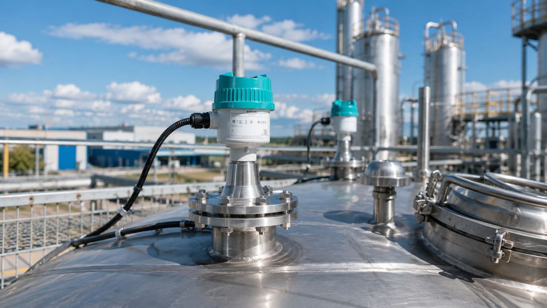
A SITRANS LR radar sensor is mechanically installed correctly on the tank but indicates almost 100 percent when the vessel is only half full. Or the measured value suddenly freezes during filling and then jumps by several metres. Does the radar sensor need to be realigned, or is the problem simply incorrect parameterisation?
With modern 80 GHz radar sensors, many apparent device faults are caused by commissioning parameters that do not match the actual tank geometry. The most common issues involve the empty and full points, measuring range, near range, installation in a nozzle and incorrectly configured false echo suppression.
Even a technically flawless sensor cannot calculate a plausible level if, for example, the distance to the tank bottom has been entered incorrectly or a fixed internal structure is interpreted as the product echo.
Suitable devices can be found under Siemens Level Measurement. Further field devices and solutions are grouped under Siemens Process Instrumentation.
Table of Contents
- How does a SITRANS LR radar sensor measure?
- Correctly distinguishing between LR100, LR110 and LR120
- Using the correct sensor reference point
- Correctly defining the empty and full points
- Accounting for tank geometry
- Selecting the correct nozzle and mounting position
- Do not make the near range or blanking distance unnecessarily large
- Correctly setting up false echo suppression
- Using the signal profile for troubleshooting
- Accounting for foam, condensation and deposits
- Dielectric constant and weak product echoes
- Special considerations for bulk solids
- Parameterisation via Bluetooth, HART or Modbus
- Systematic commissioning procedure
- Practical example on a storage tank
- Typical parameterisation errors
- What should be included in the documentation?
- Which devices and solutions are suitable?
- Conclusion
- Frequently asked questions
How does a SITRANS LR radar sensor measure?
The SITRANS LR100 series operates with 80 GHz radar. The sensor sends electromagnetic signals towards the medium and evaluates the echo reflected by the product.
The distance between the sensor reference point and the product surface is first determined from the signal propagation time or frequency shift.
The device then calculates the level from this distance.
In simplified form:
Level = distance to empty point − measured distance to product surface
This makes it clear why an incorrect tank height or incorrect empty-point setting directly results in an incorrect level.
The sensor must also determine which of the received echoes actually originates from the product surface.
Additional echoes can be caused, for example, by:
- mounting nozzles,
- tank walls,
- ladders,
- pipes,
- heating coils,
- agitators,
- cross braces,
- inlet pipes,
- tank bottom.
Reliable measurement therefore always involves two tasks:
- correct geometric scaling of the vessel,
- correct identification of the actual product echo.
Correctly distinguishing between LR100, LR110 and LR120
The SITRANS LR100 family includes several compact 80 GHz radar sensors.
| Device | Typical Version | Current Maximum Measuring Range According to Siemens |
|---|---|---|
| SITRANS LR100 | Basic device with 4 to 20 mA and fixed connection cable | up to 10 m |
| SITRANS LR110 | HART or Modbus, various approval options | up to 20 m |
| SITRANS LR120 | HART or Modbus, greater range, optional flood protection | up to 30 m |
The entire series uses a narrow 80 GHz measuring beam. This makes it easier to avoid interfering internal structures than with significantly wider radar beams.
However, the narrow beam does not replace correct installation.
If, for example, a pipe is located directly in the measuring path, even an 80 GHz sensor can receive a strong false echo.
Using the correct sensor reference point
All distance values must refer to the reference point defined by the sensor manufacturer.
On the LR100 series, the reference point is located in the area of the antenna or antenna lens.
For parameterisation, the simple distance:
tank roof to bottom
must therefore not be used if the actual sensor reference point is located several centimetres above or below it.
This difference can be relevant particularly with:
- high mounting nozzles,
- flange adapters,
- mounting brackets,
- curved vessel roofs.
Before commissioning, the actual distance from the radar reference point to the defined empty point should therefore be determined.
Correctly defining the empty and full points
At least two reference points are normally required for scaling.
Empty point or minimum
The empty point corresponds to the distance from the sensor reference point to the defined 0 percent level.
This does not necessarily have to be the geometrically lowest point of the vessel.
In a tank with:
- a conical bottom,
- a sump,
- dead volume,
- an outlet below the usable range
the operational zero point may be located above the actual tank bottom.
Full point or maximum
The full point describes the intended maximum process level.
This point is also normally not located directly at the antenna.
A permissible design distance should remain between the maximum level and the sensor.
Example:
- distance from sensor to operational empty point: 5,000 mm,
- distance from sensor to maximum level: 500 mm.
This results in a usable level range of:
5,000 − 500 = 4,500 mm
With conventional 4 to 20 mA scaling, the following may apply, for example:
- 0 percent or empty point = 4 mA,
- 100 percent or full point = 20 mA.
It is important not to confuse distance and level.
As the level rises, the measured distance to the radar becomes smaller.
Accounting for tank geometry
The radar beam should have as clear a path as possible to the product surface.
Potentially problematic features include:
- curved tank roofs,
- central mounting on round tank roofs,
- conical bottoms,
- agitators,
- inlet pipes,
- ladders and braces.
Multiple reflections can occur with curved or rounded tank roofs.
For LR100 installation, Siemens recommends maintaining a distance of at least approximately 200 mm from the tank wall where the vessel geometry allows.
At the same time, the sensor should not be mounted unnecessarily above internal structures.
For bulk solids, the position of the material cone must also be considered. Directly below the filling stream, the surface may be highly agitated and irregular.
Selecting the correct nozzle and mounting position
An unsuitable mounting nozzle is a common cause of strong near-range echoes.
Particularly problematic are:
- long and narrow metal nozzles,
- rough weld seams inside the nozzle,
- strongly protruding flange edges,
- sensors mounted at an angle,
- deposits in the antenna area.
The measuring beam can be reflected by the nozzle wall and create a strong echo immediately in front of the sensor.
Depending on the mounting arrangement, the antenna or antenna lens should be positioned in accordance with the Siemens installation instructions.
If the sensor shows incorrect values particularly at high level, the following should therefore be checked first:
- How long is the nozzle?
- What is its internal diameter?
- Does the antenna project sufficiently from a problematic nozzle?
- Is an internal structure located directly beside the radar?
- Is the antenna surface clean?
An unfavourable mechanical installation should be corrected wherever possible before attempting to compensate for it solely through parameterisation.
Do not make the near range or blanking distance unnecessarily large
With radar sensors, the terms near range, blocking distance or blanking are frequently used.
They describe an area directly in front of the sensor in which certain echoes are not used for the actual level evaluation.
The LR100 series is generally promoted as capable of measuring up to the sensor without a conventional dead zone.
However, this does not mean that a deliberately configured near range can never be useful.
A near range can be used, for example, when an unavoidable strong false echo is present directly in front of the radar.
However, the setting should be kept as small as possible.
If, for example, a blanking distance of 600 mm is configured and the process level can rise to within 400 mm of the antenna, the actual product echo will temporarily lie inside the suppressed range.
The sensor may then:
- no longer track the level,
- jump to another echo,
- hold an old value,
- generate a loss-of-echo message.
A large blanking distance should therefore not be used as a universal solution for false echoes.
For fixed interfering objects, targeted false echo suppression is normally the better method.
Correctly setting up false echo suppression
Automatic false echo suppression learns the existing echo behaviour of the vessel and can subsequently suppress known fixed reflections.
Typical sources of interference include:
- nozzles,
- pipes,
- braces,
- ladders,
- agitator components,
- weld edges.
The timing of the learning process is critical.
During the learning procedure, the actual level should preferably be well below the area in which false echoes are to be suppressed.
If automatic false echo suppression is performed when the tank is nearly full, there is a risk that the genuine product echo will be learned as part of the false-echo profile.
A suitable procedure is:
- Bring the vessel to as low a level as possible or to a known low level.
- Check the signal profile.
- Identify fixed false echoes.
- Start false echo suppression.
- Define the effective distance range only as far as required.
- Check the signal profile again after learning.
- Observe the measurement during subsequent filling.
False echo suppression should not be unnecessarily extended over the entire measuring range.
If the mechanical situation changes later, the learning procedure may need to be repeated.
Typical causes include:
- a new inlet pipe,
- tank modification,
- deposits,
- condensation,
- a new agitator,
- a changed sensor position.
Using the signal profile for troubleshooting
When radar values are implausible, the calculated percentage indication should not be considered on its own.
The echo or signal profile is much more informative.
It can show:
- where the selected product echo is located,
- which additional echoes are present,
- how strong the product echo is,
- whether a false echo becomes stronger than the product echo,
- whether echo quality changes during the process.
A typical fault pattern:
At a low tank level, the product echo is unambiguous. During filling, a false echo from an inlet pipe becomes relatively stronger. The radar algorithm subsequently switches to this echo.
In the level trend alone, this appears as a sudden jump.
In the signal profile, however, it can be seen that the sensor has simply selected the wrong echo.
The signal profile should therefore be checked at least once during commissioning under known process conditions.
Accounting for foam, condensation and deposits
Radar is more robust against many process conditions than optical or ultrasonic measuring principles. Nevertheless, process conditions can influence the echo.
Foam
Heavy or dense foam can absorb or additionally reflect radar signals depending on its composition and moisture content.
This can cause:
- the product echo to become weaker,
- the foam surface to be detected instead of the liquid,
- measurement stability to decrease.
Condensation
The LR100 series has high signal sensitivity and is designed for demanding conditions involving condensation.
Nevertheless, heavy or changed condensation can alter the echo behaviour compared with the condition learned during commissioning.
If a previously stable measured value begins to jump after prolonged operation, the antenna should therefore also be checked for condensation or deposits.
Deposits
Product deposits on the antenna, nozzle or tank wall can create new reflections.
A false echo suppression profile learned several months earlier may then no longer match the current signal profile.
Dielectric constant and weak product echoes
The strength with which a medium reflects radar energy depends, among other things, on its dielectric properties.
Media with a high dielectric constant generally produce stronger reflections than media with a very low dielectric constant.
Typical more demanding applications include, for example:
- certain hydrocarbons,
- solvents,
- light bulk solids,
- powders with low bulk density.
With a weak product echo, reflections from the tank bottom or internal structures can become relatively more significant.
Particularly when the tank is almost empty, a bottom echo can then compete with the actual product echo.
For such media, particular attention should therefore be paid to:
- mounting position,
- clear view of the medium,
- signal quality,
- echo behaviour over the entire measuring range.
Special considerations for bulk solids
With bulk solids, the surface is rarely completely horizontal.
Typical features include:
- material cones,
- discharge funnels,
- changing surface angles,
- dust,
- material movement during filling and discharge.
The radar should therefore not be aimed directly at the material impact zone.
A narrow 80 GHz beam is particularly helpful here because a suitable measuring zone can be selected more precisely.
During scaling, it must also be defined which level is operationally relevant.
With a pronounced material cone, a single radar value cannot automatically represent the exact total volume of the silo.
Suitable linearisation of the vessel geometry may therefore additionally be required for volume or mass indication.
Parameterisation via Bluetooth, HART or Modbus
The LR100 series supports wireless commissioning via Bluetooth using the Siemens SITRANS mobile IQ app.
This allows, among other things, the following to be carried out on site:
- setting the measuring range,
- parameterising the empty and full points,
- reading diagnostic values,
- checking signal behaviour,
- documenting device parameters.
Bluetooth is a local operating and commissioning interface.
It should not be confused with the actual process signal.
Depending on the device version, additional process communication options can include:
- 4 to 20 mA,
- HART,
- Modbus RTU.
For LR110 and LR120, the required communication version should therefore be defined before ordering.
Systematic commissioning procedure
- Check the device version: Verify LR100, LR110 or LR120 as well as output signal and measuring range.
- Check the installation: Inspect sensor position, nozzle, clear measuring path and internal tank structures.
- Determine the reference point: Take all distance measurements from the correct sensor reference point.
- Enter the empty point: Parameterise the distance to the operational 0 percent level.
- Define the full point: Specify the maximum intended process level.
- Check 4 to 20 mA scaling: Verify which levels correspond to 4 and 20 mA.
- Check the near range: Do not configure an unnecessarily large blanking distance.
- Check the signal profile: Identify the product echo and fixed false echoes.
- Learn false echoes: Preferably at a low level and only over the required range.
- Check echo quality: Ensure that the product echo is sufficiently unambiguous.
- Check process conditions: Take foam, condensation, dust and deposits into account.
- Change the level: Observe the measured value during filling or emptying.
- Perform a reference measurement: Compare the radar value with a known level.
- Save the diagnostics: Document the parameters and signal profile of the correctly commissioned measurement.
Practical example on a storage tank
A cylindrical storage tank is equipped with a SITRANS LR110.
The sensor is mounted 5,200 mm above the operational empty point.
The maximum permissible level is 400 mm below the sensor reference point.
The correct key values are therefore:
- empty point: 5,200 mm distance,
- full point: 400 mm distance,
- usable level range: 4,800 mm.
During initial commissioning, however, the radar indicates approximately 65 percent level when the tank is almost empty.
The signal profile shows a strong echo at 1,850 mm.
An inspection of the tank reveals:
At this distance, a metallic brace crosses the outer area of the radar beam.
The actual liquid surface is located at approximately 4,900 mm.
The installation cannot be changed mechanically.
The tank is held at a known low level and automatic false echo suppression is learned for the required range.
The signal profile is then checked again.
The echo from the brace is no longer selected as the level and the sensor tracks the liquid echo.
During controlled filling, the following reference points are compared:
| Reference Level | Radar Value | Assessment |
|---|---|---|
| approx. 10 percent | plausible | product echo stable |
| approx. 50 percent | plausible | no echo switching |
| approx. 90 percent | plausible | near range sufficiently clear |
Finally, the functioning signal profile and parameterisation are saved.
In the event of a later fault, it is then immediately possible to compare whether the echo conditions inside the tank have changed.
Typical parameterisation errors
| Error | Possible Consequence | Suitable Corrective Action |
|---|---|---|
| Tank height measured from the vessel roof instead of the sensor reference point | Constant scaling error | Use the sensor reference point |
| Empty point confused with the geometric tank bottom | 0 percent value does not correspond to usable tank volume | Define the operational empty point |
| Distance and level confused | Scaling operates in the wrong direction | Check the relationship between sensor distance and level |
| Blanking distance configured unnecessarily large | Product echo at high level is ignored | Keep the near range as small as possible |
| False echo suppression learned with a full tank | Genuine product echo may be suppressed | Learn preferably at a low level |
| Suppression range selected too large | Future genuine product echoes may be affected | Learn only the required interference range |
| Long narrow mounting nozzle ignored | Strong near-range echo | Optimise installation according to manufacturer specifications |
| Sensor aimed directly at an inlet pipe | False echoes and unstable measurement | Create a clear measuring path |
| Old false echo suppression retained after tank modification | Echo processing no longer matches the installation | Check the signal profile again and relearn if necessary |
| Condensation or deposits not considered | Measurement becomes unstable after prolonged operation | Inspect the antenna and compare echo behaviour |
| Only the percentage value considered | Cause of echo switching remains unknown | Evaluate the signal profile and diagnostic values |
What should be included in the documentation?
For reproducible commissioning, at least the following should be documented:
- device type and article number,
- measuring point designation,
- medium,
- vessel type,
- mounting position,
- sensor reference point,
- distance to empty point,
- distance to full point,
- 4 to 20 mA scaling,
- configured near range,
- false echo suppression performed,
- range of false echo suppression,
- relevant internal vessel structures,
- signal profile at low level,
- signal profile at normal operating level,
- communication type,
- firmware version where relevant,
- commissioning date.
A photograph of the mounting position and a simple tank drawing showing the most important distances are also very helpful.
This makes it possible to quickly determine during a later fault whether the mechanical or parameterised situation has changed.
Which devices and solutions are suitable?
SITRANS LR100 series
The SITRANS LR100 series comprises compact 80 GHz radar level transmitters for liquids and bulk solids.
Typical features include:
- 80 GHz radar technology,
- narrow measuring beam,
- Bluetooth commissioning,
- SITRANS mobile IQ app,
- non-contact measurement,
- high signal sensitivity,
- measurement up to the immediate sensor area.
SITRANS LR100
The SITRANS LR100 is intended for basic 4 to 20 mA applications with a fixed connection cable.
It is particularly suitable for compact applications where no additional digital process communication is required.
SITRANS LR110
The SITRANS LR110 expands the series with digital communication options and various approval options.
Depending on the version, HART or Modbus is available.
Typical applications include:
- storage tanks,
- process vessels,
- water and wastewater applications,
- chemical plants,
- industrial vessels.
SITRANS LR120
Within these three devices, the SITRANS LR120 offers the largest measuring range and, according to the current Siemens product overview, can be used for distances up to 30 m.
A version with flood protection is optionally available.
This makes it suitable, among other applications, for:
- larger tanks,
- deep shafts,
- larger silos,
- water applications,
- bulk solids applications.
Siemens level measurement
Further products for continuous level measurement and point level detection can be found under Siemens Level Measurement.
Depending on the application, ultrasonic, hydrostatic, capacitive and other measuring principles are also available in addition to radar.
ICS Schneider Messtechnik provides support in selecting the appropriate SITRANS radar, designing the mounting position, parameterising the empty and full points, and commissioning and diagnosing radar level measuring points.
Conclusion
Despite modern 80 GHz technology, a SITRANS LR radar sensor requires correctly defined vessel geometry.
The correct sensor reference point and the actual distances to the operational empty and full points are particularly important.
An incorrectly configured near range can completely remove the product echo from the evaluation at high level. The blanking distance should therefore not be increased unnecessarily.
Fixed false echoes should instead be handled specifically using automatic false echo suppression. Learning should preferably be performed at a low level so that the genuine product echo is not accidentally stored as a false echo.
For implausible measured values, the signal profile is considerably more informative than the percentage indication alone. It shows whether the sensor is actually tracking the product echo or has switched to a reflection from a nozzle, pipe or internal vessel structure.
Foam, condensation, deposits and media with weak radar reflection can additionally change the echo and must be considered during troubleshooting.
Good commissioning therefore does not end with a single plausible measured value. The radar should be checked at several known levels, and the functioning parameterisation including the signal profile should be documented.
Frequently asked questions about SITRANS LR parameterisation
What should I configure first on a SITRANS LR?
First check the installation and sensor reference point. Then define the empty and full points or the corresponding distances.
What does tank height mean for radar measurement?
For parameterisation, the relevant distance from the defined sensor reference point to the operational empty point is decisive. This does not necessarily correspond exactly to the external geometric tank height.
Why does the radar show a high level even though the tank is empty?
A false echo from a nozzle, brace or another internal tank structure may be selected as the product echo. Incorrect minimum and maximum scaling may also be the cause.
What is false echo suppression?
The echo behaviour of fixed internal structures is learned so that these reflections can be suppressed during subsequent level evaluation.
When should false echo suppression be performed?
Preferably at a low or known level. The actual product echo range should not accidentally be learned as an interference range.
Can I simply eliminate an incorrect value by increasing the blanking distance?
This is not recommended. An excessively large blanking distance can later suppress the genuine product echo at high level. Fixed false echoes should be investigated specifically and, where possible, dealt with by improving the installation or using false echo suppression.
Does the SITRANS LR100 series have a dead zone?
The LR100 series is described by Siemens as measuring up to the sensor with Zero Blanking. Nevertheless, application-specific near-range settings can still be relevant for targeted echo evaluation.
Why does the measured value suddenly jump?
The echo evaluation often switches from the product surface to another stronger echo. The signal profile normally shows clearly whether such echo switching has occurred.
Can condensation affect radar measurement?
Yes. The LR100 series is designed for demanding condensation conditions, but significantly changed condensation or deposits can still alter the signal profile.
Can radar measure through foam?
This depends strongly on the type and properties of the foam. Foam can absorb radar energy or produce reflections itself. The application should therefore be evaluated under actual process conditions.
Why is the dielectric constant important?
It influences how strongly the medium reflects radar energy. Media with weak reflection produce a smaller product echo, which means that other reflections can become relatively more significant.
Is Bluetooth the same as HART?
No. On the LR100 series, Bluetooth is used particularly for local parameterisation with SITRANS mobile IQ. HART or Modbus are communication interfaces for integrating the measuring instrument into automation and control systems.