


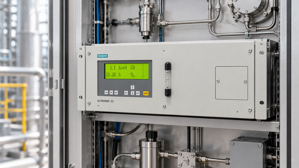
A Siemens ULTRAMAT 23 has been operating reliably in an industrial process gas analysis system for a considerable period. Suddenly, the measured values begin to fluctuate. The sample gas flow occasionally decreases, while the analyser intermittently reports a flow fault. After the next AUTOCAL cycle, the readings initially appear stable again. Shortly afterwards, however, the problem returns.
In such situations, the cause does not necessarily lie in the gas analysis itself. Fluctuating sample gas flow may result from contaminated filters, declining pump performance, condensate in the sample line, leaks or increased resistance at the gas outlet. Incorrect pump settings and different operating conditions during measurement and AUTOCAL may also play a role.
The ULTRAMAT 23 provides device-specific diagnostic and adjustment functions for these situations. Depending on the configuration, an internal sample gas pump, a flow indicator on the front panel, a flow switch and corresponding fault messages are available. However, the gas paths and available functions differ between device variants.
This technical article explains how to systematically investigate fluctuating sample gas flow in the Siemens ULTRAMAT 23. It focuses on pump operation, analysis filters, condensate separators, flow indication and operating mode configuration. The effects on measurement quality, AUTOCAL, signal outputs and integration into process automation are also discussed.
Table of Contents
- Identify the Fault Pattern and Affected Measurement Function
- Understand the Design and Measuring Principle of the ULTRAMAT 23
- Distinguish Between Device Variants and Internal Gas Paths
- Trace the Complete Sample Gas Path
- Check the Permissible Sample Gas Flow and Connection Conditions
- Correctly Interpret the Flow Indicator and Flow Switch
- Check the Internal Sample Gas Pump and Pump Settings
- Consider External Pumps and Long Sample Lines
- Check Analysis Filters and Safety Filters for Contamination
- Inspect Condensate Separators, Gas Coolers and Moisture
- Identify Leaks and Unwanted Dilution of the Gas Sample
- Assess the Gas Outlet, Backpressure and Flow Resistance
- Distinguish Pump Behaviour During Measurement and AUTOCAL
- Understand the Effects on Concentration Readings and Response Time
- Calculation Example: Sample Gas Transport at Different Flow Rates
- Consider Different Gas and Sensor Configurations
- Test the Sample Gas Supply and Analyser Separately
- Check Diagnostic Values, Interfaces and Output Signals
- Distinguish AUTOCAL, Test Gas Verification and Adjustment
- Perform a Systematic Test Procedure
- Diagnose Typical Fault Patterns and Their Causes
- Suitable Siemens Process Analytics Products from ICS Schneider
- Conclusion: Check the Entire Sample Gas Path Before Readjusting the Analyser
- Frequently Asked Questions About Fluctuating Sample Gas Flow in the ULTRAMAT 23
1. Identify the Fault Pattern and Affected Measurement Function
When troubleshooting, the first step is to establish what is actually fluctuating. Not every change in the concentration reading means that the sample gas flow has changed. Conversely, fluctuating flow may occur without immediately producing a noticeable change in concentration.
Three quantities should therefore be distinguished during diagnosis: the actual sample gas flow rate, the gas concentration determined by the analyser, and the operating or fault status of the instrument.
If the flow indicator fluctuates visibly, this suggests a change in gas delivery or flow conditions. If the flow remains stable while only the concentration reading fluctuates, other influencing factors such as process composition, sensor drift, temperature or electrical signal processing must be considered.
The timing of the fault is also important. Does it occur only immediately after switching on, when changing between AUTOCAL and measurement mode, or during particular process conditions?
A fault that occurs only during AUTOCAL may be associated with the zero gas path, valve switching or pump configuration. Continuously insufficient sample gas flow, on the other hand, is more likely to indicate a permanent restriction in the gas path or inadequate delivery capacity.
The existing condition should therefore be documented before changing the device configuration. This includes the exact ULTRAMAT 23 variant, displayed measured values, flow rate, existing fault messages and relevant pump settings.
Premature readjustment of the analyser is not advisable while the gas supply is not operating under the specified conditions.
2. Understand the Design and Measuring Principle of the ULTRAMAT 23
The Siemens ULTRAMAT 23 is a multi-component gas analyser for continuous extractive process gas analysis.
Depending on the device configuration, different measuring principles can be combined. These include non-dispersive infrared measurement (NDIR), a UV photometer and electrochemical or paramagnetic measuring methods for specific gas components.
NDIR technology is suitable, for example, for measuring infrared-active gases such as CO, CO₂ or CH₄. Additional components can also be measured with suitable configurations.
Corresponding UV measurement modules are available for certain UV-active gases. Depending on the device variant, oxygen can be measured electrochemically or using a paramagnetic method. Versions with electrochemical H₂S measurement are also available for suitable applications, such as biogas plants.
Depending on the configuration, up to four gas components can be measured with one ULTRAMAT 23.
The instrument operates on the extractive principle. The gas sample to be analysed must therefore first be extracted from the process and transported to the measuring cell.
Measurement quality depends not only on the optical or electrochemical measuring principle. It is equally important that the sample gas reaches the analyser at a suitable temperature and humidity, with sufficient flow and an unchanged or adequately representative composition.
Depending on the configuration, the internal gas path may contain pump, filter, condensate and monitoring components. The components actually present depend on the ordered device version.
The specific gas path diagram of the ULTRAMAT 23 in use must therefore be consulted during troubleshooting.
3. Distinguish Between Device Variants and Internal Gas Paths
The ULTRAMAT 23 is available, among other configurations, as a 19-inch rack-mounted instrument and as a benchtop or portable version. The variants also differ in their measuring components, gas routing and available accessory functions.
Certain device configurations have an internal sample gas pump. In other versions, gas is delivered exclusively by an external device.
Siemens documents an integrated sample gas pump for the benchtop version. In the corresponding 19-inch rack-mounted instrument, the internal pump may be available as an option depending on the configuration.
However, the option of an integrated pump does not apply without restriction to all gas paths. According to the Siemens operating instructions from 2022, the internal pump cannot be combined with piped gas paths or the UV module, for example.
The flow indicator on the front panel is also configuration-specific. Siemens describes a front-panel flow indicator for corresponding sample gas paths, but not for piped gas paths.
In the benchtop version, a condensate separator and safety filter may be present in the designated internal gas path. Certain devices with piped gas paths, however, have neither an internal safety filter nor a condensate separator.
This results in different requirements for external gas conditioning and troubleshooting.
A missing internal filter is therefore not necessarily a fault. Likewise, the presence of a pump operating function in the manual does not mean that every ULTRAMAT 23 has an integrated pump.
Before carrying out maintenance, the article number, hardware configuration, installed measuring modules and corresponding version of the operating instructions should therefore be identified.
4. Trace the Complete Sample Gas Path
In extractive gas analysis, the measurement chain begins at the process sampling point. The gas path may contain various components before the gas reaches the analyser.
A typical arrangement can be simplified as follows:
Gas sampling probe → Sample line → Gas cooler / Condensate conditioning → Analysis filter → Suitable gas delivery system → ULTRAMAT 23 → Safe gas exhaust
The actual arrangement depends on the gas conditioning system and device variant used. In particular, pumps and other components may be positioned at different designated locations.
In an ULTRAMAT 23 with an integrated pump, part of the gas delivery system is located inside the analyser. In a version without an internal pump, the necessary gas delivery or pressure supply must be provided externally.
Depending on the configuration, the device also has additional gas connections for AUTOCAL, zero gas, test gas or additional measuring channels.
For diagnosis, the individual gas paths must be clearly identified. A problem in the process gas path does not necessarily occur during AUTOCAL. Conversely, a fault may affect only the zero gas supply.
A complete diagram showing all components, their flow direction, intended valve positions and associated operating conditions is particularly useful.
The gas path should not be modified without appropriate approval. Additional valves, filters or long lines can affect flow resistance and gas transport time.
5. Check the Permissible Sample Gas Flow and Connection Conditions
The Siemens documentation specifies a sample gas flow rate of 72 … 120 l/h for the ULTRAMAT 23. This corresponds to 1.2 … 2.0 l/min.
These specifications provide an important starting point for diagnosis. The specific setpoint within the permissible range depends on the device configuration and intended measurement task.
| Parameter | Manufacturer Specification | Significance for Troubleshooting |
|---|---|---|
| Sample gas flow | 72 … 120 l/h or 1.2 … 2.0 l/min | Check actual flow during the intended measurement operation |
| Sample gas temperature | 0 … +50 °C | Evaluate gas conditioning and temperature at the instrument inlet |
| Sample gas humidity | Less than 90 % relative humidity, non-condensing | Check humidity conditions and possible condensation |
| With internal pump | Pressureless suction operation at the inlet; outlet unpressurised relative to ambient pressure | Avoid unsuitable inlet pressurisation or outlet restriction |
| Without internal pump | Maximum inlet overpressure relative to ambient pressure of 45 hPa; outlet unpressurised | Coordinate external gas delivery with permissible pressure conditions |
| Longer sample lines | Siemens specifies an external gas sampling pump for lines exceeding 20 m in the described gas conditioning arrangement | Evaluate pump sizing and pressure losses across the complete system |
These specifications are taken from the Siemens ULTRAMAT 23 operating instructions, edition 04/2022. The technical data of the installed device variant and any special requirements of its measuring modules are decisive for a particular installation.
It is important to distinguish between the general permissible flow range and the conditions under which certain accuracy specifications apply.
For example, Siemens specifies reference conditions for the IR analyser section with a sample gas flow of approximately 1.2 l/min and defined pressure and temperature conditions.
The mere presence of gas flow does not therefore automatically mean that all metrological requirements are met.
The pressure limits must also not be confused with the conditions for a separate leak test prescribed by the manufacturer. Normal measurement operation and testing are different operating conditions.
6. Correctly Interpret the Flow Indicator and Flow Switch
Appropriately equipped ULTRAMAT 23 variants have a flow indicator on the front panel. It allows the sample gas flow to be monitored during operation.
The first step in troubleshooting is to observe whether the indicator remains continuously stable or fluctuates over time.
A repeatedly decreasing indication may suggest changing flow resistance, inadequate pump delivery or another problem with the gas supply.
In corresponding gas path configurations, the ULTRAMAT 23 also provides flow monitoring via a flow switch or its associated internal monitoring function.
The operating instructions describe a separate device test for this purpose. It indicates whether the monitored flow condition is recognised as sufficient or insufficient.
These two types of information must not be treated as equivalent.
A front-panel flow indicator allows the gas flow to be observed. The flow switch test or corresponding device status, on the other hand, evaluates the intended monitored condition.
A flow status reported as sufficient is not automatically an accurate digital measurement of the volumetric flow rate in l/min.
Quantitative verification may therefore require a suitable separate flowmeter approved for the gas type and measuring range.
If the front-panel indicator shows a plausible flow while the electronic monitoring function repeatedly reports a fault, the flow switch and the associated electrical or pneumatic conditions must also be checked.
However, a defective flow switch should only be suspected after insufficient gas flow, leaks and other possible causes have been ruled out.
7. Check the Internal Sample Gas Pump and Pump Settings
In an ULTRAMAT 23 with an integrated sample gas pump, the pump transports the sample gas through the designated gas path.
Pump operation must match the respective operating condition. Siemens distinguishes between the conditions during actual measurement and during AUTOCAL.
The configuration menu provides corresponding settings for pump operation during CAL and MEAS.
On appropriately equipped devices, pump delivery capacity can be adjusted using the pump and flow setting menu. The Siemens operating instructions describe the parameter area “Pump/LCD contrast” and the associated function for adjusting the pump and flow.
Changing the pump output affects the sample gas flow. On the corresponding device variants, the change can be observed on the flow indicator or in the flow status recognised by the instrument.
During diagnosis, it should first be checked whether the pump is actually switched on in the intended operating mode.
If the pump is not running, the cause may lie in the configuration, an intended external control arrangement or an actual pump fault.
However, a running pump does not guarantee sufficient sample gas flow. A contaminated sample line or clogged filter can increase flow resistance to such an extent that the amount of gas actually delivered becomes insufficient.
Wear or declining pump performance are also possible causes.
For this reason, immediately increasing pump output when flow is too low is not advisable. Filters, condensate separators, lines and other gas path components should be investigated first.
A higher pump setting may temporarily compensate for existing flow resistance without eliminating the underlying cause.
Work on the pump and any necessary replacement must be carried out in accordance with the Siemens maintenance instructions.
8. Consider External Pumps and Long Sample Lines
Long sample lines increase resistance to gas flow. They also increase the volume of gas that must be exchanged when switching between different concentrations.
In the standard gas conditioning arrangement described for the ULTRAMAT 23, Siemens specifies the use of an external gas sampling pump for sample lines longer than 20 m.
This statement must not be interpreted as a general indication that every shorter line can be operated without an external pump. Actual delivery requirements also depend on internal diameter, line routing, filter loading and other components.
An external pump must be capable of providing the required sample gas flow at the existing pressure losses.
It is important that delivery capacity is not assessed solely on the basis of a nominal value measured with an unrestricted outlet. The decisive factor is the gas flow actually achieved under the operating conditions of the complete sampling system.
The pump position must be compatible with the intended gas conditioning system and the permissible pressure loading of the analyser.
In an ULTRAMAT 23 configuration without an integrated pump, particular attention must be paid to the permissible pressure conditions at the analyser inlet and the requirement for an unpressurised gas outlet.
An additional pump arrangement must not expose the analyser to pressures outside its approved operating conditions.
The response time of the measurement point is particularly important for longer lines. A higher sample flow may shorten the theoretical transport time, but must not cause the permissible limits of the measurement system to be exceeded.
Correct design therefore requires the sample line, gas conditioning system, delivery equipment and analyser to be considered together.
9. Check Analysis Filters and Safety Filters for Contamination
Filters protect the sample gas path against particles and other contaminants. At the same time, they introduce additional flow resistance.
A clean, correctly sized filter may have only a small effect on the intended gas flow. However, its pressure drop typically increases as contamination accumulates.
A pump with limited delivery capacity may consequently transport progressively less gas through the complete sampling system.
Siemens describes an analysis filter with a filtration rating of approximately 1 … 2 µm, among other components, for the standard external gas conditioning arrangement.
Depending on the device variant, additional internal safety filters or a condensate separator with a filter may also be present.
During troubleshooting, it is important to distinguish which filter is actually contaminated. A clogged sampling filter directly at the process can cause flow problems similar to those produced by an internal safety filter.
Replacing only the easily accessible filter at the analyser may therefore not necessarily resolve the problem.
Even filters that appear clean may have increased flow resistance, for example if fine particles or moisture have affected the filter medium.
Filter replacement should therefore be based on actual condition, manufacturer requirements and, where necessary, suitable pressure-drop or flow tests.
An unsuitable replacement filter can also be problematic. Filter material, filtration rating, chemical resistance and flow resistance must be compatible with the gas type and intended analysis system.
Particularly with reactive gases, unsuitable filter materials may also alter the composition of the gas sample.
Contaminated filters should not simply be bypassed by briefly removing them during ongoing process operation. This could allow particles or liquids to enter sensitive measuring components.
10. Inspect Condensate Separators, Gas Coolers and Moisture
Moisture is a common cause of unstable sample gas flow. When warm, humid process gas is cooled, water vapour can condense and accumulate as liquid in the sample line.
Condensate may partially or completely block the flow cross-section. Depending on the line routing, even small liquid accumulations can produce variable flow resistance.
If the liquid is intermittently moved along by the gas flow, irregular flow fluctuations can result.
A gas cooler or suitable sample conditioning system is intended to prevent unsuitable humidity conditions from reaching the analyser.
Siemens specifies less than 90 % relative sample gas humidity under non-condensing conditions as a general inlet requirement for the ULTRAMAT 23.
This does not mean that every gas sample should be dried completely. Certain electrochemical sensor variants may have additional requirements for a sufficient level of humidity.
Suitable conditioning must therefore match the measuring component being used.
The condensate drain of a cooler or separator can also become a source of faults. An overfilled condensate container, blocked drain or unsuitable draining arrangement can affect the gas path.
During diagnosis, the amount of condensate, cooler operation, separator condition and possible liquid accumulation in low sections of the line should therefore be checked.
A fault must not be remedied merely by forcing liquid further towards the analyser.
Condensate may also cause concentration losses for water-soluble measured components. In this case, the representativeness of the gas sample must be assessed in addition to its flow rate.
11. Identify Leaks and Unwanted Dilution of the Gas Sample
A leaking connection in the sample gas path can have different effects. In a suction-based sampling system, ambient air may enter through the leak.
This can change the composition of the gas sample. The concentration of a particular measured component may appear lower even though the actual process concentration has not changed.
When measuring oxygen, the ingress of ambient air can conversely produce a higher indicated O₂ concentration.
The effect on flow also depends on the location of the leak and the gas path architecture. Not every leak necessarily produces a noticeably lower flow rate at every measurement location.
A normal reading at the analyser is therefore insufficient evidence that the complete sample line is leak-tight.
Typical leak points include hose connections, fittings, filter housings, seals, condensate containers and ageing flexible lines.
Suitable leak tests in accordance with the Siemens operating instructions and the requirements of the complete gas conditioning system should be used for investigation.
Siemens describes a specific procedure for testing the ULTRAMAT 23 gas path for leaks. Its test conditions must be clearly distinguished from the permissible pressure conditions during normal measurement operation.
Improvised pressurisation using an unsuitable test medium or excessive pressure can damage the measuring chambers.
Connections must also not be opened without control when toxic, flammable or oxygen-displacing gases are involved. The gas system must be made safe according to the intended plant and safety procedure before such work is performed.
12. Assess the Gas Outlet, Backpressure and Flow Resistance
When sample gas flow is insufficient, the pump or filter is often examined first. However, a possible cause may also be located downstream of the analyser.
Increased backpressure at the gas outlet affects the pressure conditions throughout the complete gas path.
Siemens requires the sample gas outlet of the described ULTRAMAT 23 configurations to be unpressurised relative to the ambient atmosphere.
A long or restricted exhaust line, unsuitable valves or a blocked outlet can therefore be problematic.
Liquid accumulation in a downstream line can also change the outlet resistance.
It is particularly important to distinguish between the outlet at the analyser and the safe discharge of the gas from the building or plant area.
Safe gas exhaust may be necessary because of the gas type. However, it must be designed so that the permissible pressure conditions at the analyser are maintained.
Discharging hazardous process gases directly into the workplace is not an acceptable simple diagnostic measure.
If increased outlet resistance is suspected, the exhaust system must be examined according to an appropriate safe procedure.
Even with an otherwise correctly functioning ULTRAMAT 23, a change in downstream gas routing can affect measurement conditions and the required gas delivery capacity.
13. Distinguish Pump Behaviour During Measurement and AUTOCAL
The ULTRAMAT 23 has an automatic adjustment function known as AUTOCAL. Depending on the measuring component and device configuration, suitable ambient air or a designated zero or reference gas is used for this purpose.
During AUTOCAL, the gas path may differ from the normal process gas path. The corresponding valves and gas connections are controlled according to the device configuration.
In a device with an internal sample gas pump, it can also be specified whether the pump operates during AUTOCAL or normal measurement mode.
Siemens describes the parameters “Pump at CAL” and “Pump at MEAS” for this purpose.
These settings must match the actual gas system configuration.
If the pump operates correctly during measurement but AUTOCAL terminates with a flow fault, the AUTOCAL gas path and the associated pump settings should be checked first.
Conversely, successful AUTOCAL operation does not automatically confirm that the process gas line is unrestricted and leak-tight. Different gas paths may be used.
The supply of suitable zero gas is also important. For certain CO₂ measuring ranges, for example, additional removal of CO₂ from the ambient air used for AUTOCAL may be necessary.
Using ambient air is therefore not suitable for every measurement task without additional conditions.
The Siemens fault diagnostics explicitly distinguish between flow faults occurring during measurement and those occurring during AUTOCAL.
This distinction should be used during troubleshooting rather than treating both messages automatically as evidence of a defective pump.
14. Understand the Effects on Concentration Readings and Response Time
Fluctuating sample gas flow can alter the time-dependent response of the gas analysis system. Under otherwise identical conditions, a lower actual volumetric flow rate means that exchanging the gas volume in the line and measuring system takes longer.
Consequently, a change in process concentration may appear later at the analyser.
Changes in pressure, humidity and gas composition can also influence the measurement itself.
For the IR measuring channels, the specified response time of the ULTRAMAT 23 depends on factors including the analysis chamber length, sample gas line and configured electronic damping.
The operating instructions describe adjustable time constants and corresponding parameters for this purpose.
A slowly responding concentration value can therefore have several causes: a long transport path, low sample gas flow, high damping or a combination of these influences.
The time delay must be distinguished from an actual concentration error.
Low gas flow does not necessarily cause the same measurement error for every gas type and sensor technology. However, it may result in operation outside the specified measurement conditions and thus compromise the reliability of the results.
Additional dilution through leaks or the loss of certain gas components through condensation and interactions with the sampling system is particularly critical.
A stable concentration reading is therefore insufficient evidence that the sample gas flow is correct.
For evaluation, the concentration signal, flow status and time-dependent behaviour should be recorded together.
15. Calculation Example: Sample Gas Transport at Different Flow Rates
The effect of sample gas flow on the theoretical transport time can be estimated from the internal volume of the line.
For a circular sample line with a constant internal diameter:
V = π · d² · L / 4
Here, V is the internal line volume, d is the internal diameter and L is the line length.
The idealised volumetric exchange time is calculated as:
tideal = V / Q
Q denotes the actual volumetric flow rate under the conditions considered.
One example considers a sample line with an internal diameter of 4 mm. At a length of 20 m, its geometric internal volume is approximately 0.251 l.
At a flow rate of 1.2 l/min:
tideal = 0.251 l / 1.2 l/min ≈ 0.209 min ≈ 12.6 s
The following table shows different line lengths and flow rates:
| Line Length | Volumetric Flow Rate | Line Volume | Ideal Exchange Time |
|---|---|---|---|
| 10 m | 1.2 l/min | 0.126 l | approx. 6.3 s |
| 20 m | 1.2 l/min | 0.251 l | approx. 12.6 s |
| 30 m | 1.2 l/min | 0.377 l | approx. 18.9 s |
| 30 m | 2.0 l/min | 0.377 l | approx. 11.3 s |
| 30 m | 0.8 l/min | 0.377 l | approx. 28.3 s |
The final table entry with a flow rate of 0.8 l/min is included solely to illustrate insufficient sample gas flow. It is below the previously specified Siemens flow range of 1.2 … 2.0 l/min.
The example shows that the theoretical exchange time increases considerably as the volumetric flow rate decreases.
However, this calculation does not describe the complete response time of the ULTRAMAT 23.
It does not account for the gas volume inside the analyser, filters, condensate separators, flow profiles, gas interactions or the actual sensor response time.
The displayed concentration may also develop differently from the simple volumetric calculation because of mixing processes and the configured damping.
For a reliable diagnosis, the actual response behaviour must therefore also be investigated using a suitable test gas application.
Particularly for lines longer than 20 m, the use of a suitable external gas sampling pump as described in the Siemens operating instructions must also be considered.
16. Consider Different Gas and Sensor Configurations
The precise significance of a flow fluctuation also depends on the measuring components installed in the ULTRAMAT 23.
In NDIR measurement, the absorption of infrared radiation by the respective gases is evaluated. The measured value therefore depends on the corresponding optical and gas-physical conditions.
With electrochemical sensors, factors including gas composition, humidity and sensor characteristics may play a particularly important role.
Siemens specifies particular sample gas requirements for electrochemical O₂ measurement. In this configuration, a completely dry gas sample is not necessarily permissible under all conditions.
Special requirements concerning permissible accompanying gases and operating conditions also apply to H₂S measurement.
In UV measurement, particles or aerosols may affect the optical measurement. Siemens requires suitable conditioning for the corresponding UV analysis components to ensure that the gas sample is sufficiently free from particles and aerosols.
Appropriate filtration and humidity conditioning must therefore always be considered in conjunction with the specific measuring principle installed.
Simply replacing the gas conditioning system with a supposedly more powerful standard solution can be problematic if the measured component itself is altered or removed from the gas.
The use of an internal sample gas pump and certain internal gas paths is also not provided for in every sensor configuration.
For diagnosis and device selection, at least the complete article number, installed measuring modules and intended gas type are therefore required.
17. Test the Sample Gas Supply and Analyser Separately
An important diagnostic strategy is to distinguish the influence of the upstream sample gas path from the operation of the analyser itself.
If a fault in the gas conditioning system is suspected, a defined gas supply may be applied directly to the designated analyser inlet under suitable conditions approved by the manufacturer.
The investigation must account for gas type, flow, temperature, pressure and humidity conditions.
If the analyser responds stably to an appropriate direct gas supply while measurements fluctuate when using the complete sampling path, this suggests an influence from the upstream gas routing.
However, this observation does not yet provide complete proof of the specific cause. Leaks, filter loading and condensate, for example, can all cause unusual behaviour.
Conversely, a measurement that continues to fluctuate despite a stable and suitable gas supply may indicate an internal measurement or electronics fault.
The corresponding device conditions and diagnostic information must be considered for a reliable assessment.
A meaningful comparison therefore distinguishes between testing the analyser with a suitable direct gas supply and testing the complete system through the actual process gas sampling point.
The test location must be clearly documented. A successful test gas check directly at the analyser does not automatically confirm the operation of the entire sample line.
With hazardous process gases, the gas supply must not be switched or opened using improvised procedures. Such work requires a suitable and approved test procedure.
18. Check Diagnostic Values, Interfaces and Output Signals
The ULTRAMAT 23 provides menu-guided diagnostic, parameter and configuration functions. Depending on the device and configuration, faults, maintenance requests and relevant operating conditions can be read out.
For troubleshooting, information about gas flow, pump status, AUTOCAL behaviour and existing fault messages is particularly important.
On suitably equipped instruments, the flow switch can be checked using a separate device test. This test evaluates the flow status but does not replace quantitative measurement of the actual volumetric gas flow rate.
Pump configuration must also match the existing gas path. Changes to pump output, operating states or valve control should only be made after the cause has been assessed.
Depending on the configuration, the ULTRAMAT 23 provides analogue signal outputs, relay functions and digital communication options for integration into process automation.
Siemens documents RS-485 as a device interface, along with corresponding expansion and connection options, for example via PROFIBUS or suitable interface converters.
SIPROM GA software can be used for corresponding service and maintenance tasks.
When investigating a fault, it is important to distinguish between the concentration value displayed locally and the signal transmitted to the control system.
If the instrument displays stable values locally while the process control system receives a fluctuating value, electrical transmission, scaling or output signal configuration may be involved.
If the local concentration display itself fluctuates while the sample gas flow is also unstable, the gas supply should be investigated first.
For reliable fault handling, it is also necessary to define how higher-level systems respond to flow faults, maintenance conditions or invalid measured values.
An incorrect sample gas supply must not go unnoticed and be interpreted as a normal process measurement.
19. Distinguish AUTOCAL, Test Gas Verification and Adjustment
The Siemens ULTRAMAT 23 provides an automatic adjustment function known as AUTOCAL. Ambient air can be used for suitable measuring components.
The function supports economical, automated checking or correction of certain instrument characteristics.
However, it is not equivalent to a complete verification of the entire process gas sampling system.
It is particularly important to distinguish between automatic analyser adjustment and verification using suitable reference gases of known composition.
If the measurement point is used for regulatory emissions monitoring, quality-relevant process measurement or another demanding application, additional requirements concerning inspection and adjustment intervals may apply.
The manufacturer’s requirements for the respective measuring component must also be observed. For example, certain CO₂ measuring ranges may require additional measures to provide suitable AUTOCAL gas.
Automatic zero-point adjustment cannot reliably correct insufficient sample gas flow.
Nor can a damaged filter, leaking line or inadequate pump performance be repaired through readjustment.
Before performing another adjustment, it should therefore be checked whether the gas supply meets the intended operating conditions.
Following appropriate maintenance or repair, a suitable functional test or adjustment may be required. The exact scope depends on the manufacturer’s procedure and the requirements of the measurement task.
For a complete assessment, it is also necessary to distinguish whether test gas is applied directly at the analyser or at the process gas sampling point.
Only the second arrangement includes the upstream gas conditioning and transport path when a suitable test procedure is used.
20. Perform a Systematic Test Procedure
Reproducible troubleshooting should begin by documenting the existing condition. The complete sample gas path is then investigated step by step.
The following test procedure assumes an appropriate, approved maintenance procedure and suitably qualified personnel.
- Identify the device variant: Determine the complete article number, installed measuring modules, gas path and available pump options.
- Document the fault pattern: Record concentration values, flow indication, operating status and existing fault messages.
- Check operating conditions: Compare the actual sample gas flow with the permissible conditions of the device variant.
- Distinguish measurement and AUTOCAL operation: Check whether the fault occurs only during a particular operating mode.
- Check pump status: Where an integrated pump is present, verify its intended operating condition and configuration.
- Assess the sample line: Record its length, internal diameter, line damage and possible mechanical restrictions.
- Inspect gas conditioning: Check the sampling probe, analysis filters, safety filters and other designated components.
- Assess condensate management: Inspect the gas cooler, condensate separator, drain and possible liquid accumulation.
- Check the gas path for leaks: Apply the designated leak test according to the manufacturer’s procedure.
- Check the gas outlet: Evaluate permissible outlet pressure conditions and flow resistance of the safe gas exhaust.
- Test flow monitoring: On suitably equipped devices, compare the flow switch test with the front-panel indication.
- Assess external gas delivery: Where an external pump is installed, check its actual delivery capacity in the intended complete system.
- Compare gas supply and analyser behaviour: Where permitted, compare a suitable defined direct gas supply with the complete sampling path.
- Record response behaviour: Document flow, concentration indication and fault status under comparable conditions.
- Check electrical signals: Compare the local display, analogue or digital output and the indication in the process control system.
- Perform necessary corrective measures: Repair or replace defective or contaminated components according to the manufacturer’s procedure.
- Repeat functional testing: Verify stable gas flow, intended measurements and correct processing of status messages.
- Document maintenance: Record the initial condition, cause, actions performed and final test results.
The sequence is important because settings should not be changed prematurely. For example, increasing pump output before identifying a blocked filter can conceal the original cause of the fault.
Fault messages should also only be cleared after the relevant information has been documented and the causes investigated.
A concentration value that has become stable again does not alone confirm that every function of the measurement point has been restored correctly.
Before releasing the system for operation, sample gas flow, analyser function, AUTOCAL and, where applicable, the connected fault and maintenance messages should therefore be checked together.
21. Diagnose Typical Fault Patterns and Their Causes
The following overview links typical ULTRAMAT 23 observations to possible causes and suitable diagnostic measures.
| Observation | Possible Cause | Suitable Check |
|---|---|---|
| Flow indication gradually decreases over time | Increasing filter contamination or rising flow resistance | Check the sampling filter, analysis filter and complete sample gas path |
| Flow fluctuates irregularly | Condensate in the gas path, varying line resistance or unstable delivery conditions | Check the condensate separator, gas cooler and low points in the line |
| Flow fault during measurement | Blocked or leaking gas path, insufficient pump performance, pump or switch fault | Use Siemens fault diagnostics; check the gas path and pump operation separately |
| Flow fault only during AUTOCAL | Blocked zero gas path, valve switching problem or unsuitable pump configuration | Check the AUTOCAL gas path and pump setting for CAL |
| Pump runs, but sample gas flow is too low | Filter loading, restricted line, inadequate delivery capacity or unfavourable pressure conditions | Investigate actual gas flow and flow resistance |
| Front-panel indicator shows gas flow, but electronic monitoring reports a fault | Insufficient flow or possible fault in the monitoring function | Compare quantitative flow measurement with the flow switch test |
| CO₂ or another process gas concentration appears too low | Dilution through leaks or possible gas losses during sampling | Check the gas path for leak tightness and material compatibility |
| O₂ indication is unexpectedly high | Possible ingress of ambient air into a suction-based sample line | Investigate leaks and the actual gas composition |
| Measured value responds significantly more slowly than before | Reduced gas flow, increased damping or additional transport delay | Check sample gas flow, gas path volume and time constants |
| Fault occurs after modification of the exhaust line | Increased backpressure at the gas outlet | Check pressure conditions and the permissible gas exhaust arrangement |
| Analyser measures stably with direct test gas supply but not through the process line | Influence of upstream sampling, gas conditioning or gas delivery | Investigate the complete sampling system step by step |
| Local display is stable, but the process control system shows fluctuating values | Fault in signal output, wiring or configuration | Check the analogue or digital signal path separately |
The possible causes listed are diagnostic indications, not definitive remote diagnoses.
It is particularly important to distinguish between an actual fault in gas delivery and an error in electronic measurement processing.
During a flow fault, the sensor may continue displaying plausible concentration values. However, these values must be assessed in terms of their validity and the actual sampling conditions.
A fault involving the pump, gas paths or flow switch must not be addressed solely by recalibrating the gas concentration measurement.
The cause must be identified in the corresponding part of the measurement chain and corrected professionally.
22. Suitable Siemens Process Analytics Products from ICS Schneider
22.1 Siemens ULTRAMAT 23: Multi-Component Gas Analyser with Integrated Diagnostics
The Siemens ULTRAMAT 23 is a multi-component gas analyser for continuous extractive measurements.
Depending on the configuration, up to four gas components can be measured. Different measuring methods are available for this purpose, including NDIR technology for infrared-active gases, UV photometry and suitable oxygen or H₂S sensors.
One important feature is menu-guided operation with corresponding diagnostic and maintenance functions.
The AUTOCAL function enables automatic adjustment of suitable measuring components under the specified reference conditions.
For troubleshooting fluctuating sample gas flow, the available gas path options, front-panel flow indicator and respective pump functions are particularly relevant.
The specific configuration may include an internal sample gas pump, additional filter or condensate components and different sensor modules.
Communication with higher-level systems is also supported. Depending on the configuration, analogue output signals, relay functions and suitable digital interfaces are available.
For application-specific selection, gas types, concentration ranges, sample gas conditioning, the pump concept and intended operating conditions must be defined together.
22.2 Siemens SIPROCESS GA700: Modular System for Demanding Process Gas Analysis
The Siemens SIPROCESS GA700 platform allows different gas analysis modules to be combined in a suitable housing system.
Depending on the application, modules such as ULTRAMAT 7, OXYMAT 7 or CALOMAT 7 can be used.
The platform is designed for modular integration into industrial process analysis systems.
For new installations or extensive modernisation projects, such a system may be of interest when different gas analyses, interfaces or installation requirements must be combined.
However, selecting a different analyser does not automatically eliminate problems in an existing sample line. A modular gas analysis system also requires suitable gas conditioning, delivery conditions and safe gas exhaust.
22.3 Siemens SIPROCESS GA700 ULTRAMAT 7: Infrared Gas Analysis with Advanced Diagnostic Capabilities
The Siemens ULTRAMAT 7 module is designed to measure infrared-active gas components.
Depending on the configuration, typical measured components include CO, CO₂, NO, SO₂, CH₄ and other infrared-active gases.
The module provides high selectivity, extensive adjustment options and corresponding diagnostic and maintenance functions.
It can be used in suitable rack-mounted or wall-mounted housings belonging to the SIPROCESS GA700 platform.
For industrial process applications, the possibility of integrating measurement and diagnostic functions into a more comprehensive analysis system is particularly valuable.
However, when comparing it with an ULTRAMAT 23, the measured components, measuring ranges, gas routing, installation conditions and existing process control interfaces must be considered. An ULTRAMAT 7 is not automatically an interchangeable replacement without modifications.
22.4 Siemens SIPROCESS UV600: Extractive UV Gas Analysis for Specific Gas Components
The Siemens SIPROCESS UV600 is an extractive gas analyser for UV-active gas components.
Depending on the configuration, it is suitable for measuring low concentrations of NO, NO₂, SO₂ or H₂S.
For suitable applications, the UV measuring principle provides high selectivity and low cross-sensitivity to certain accompanying gases.
For the SIPROCESS UV600 as well, the sample gas must be conditioned according to the technical requirements and delivered to the analyser under suitable flow conditions.
Options such as an internal sample gas pump, flow monitoring and humidity monitoring are available for certain configurations.
The functions required depend on the target gas, measurement task and complete sampling installation.
Further Siemens gas analysers and suitable process analytics products are available from ICS Schneider in the Process Analytics Equipment / Gas Analysers category and the Siemens – Process Instrumentation section.
23. Conclusion: Check the Entire Sample Gas Path Before Readjusting the Analyser
Fluctuating sample gas flow in the Siemens ULTRAMAT 23 does not necessarily indicate a fault in the actual gas analysis function.
Changes in gas delivery, contaminated filters, condensate, leaks or unfavourable pressure conditions may frequently be responsible.
The exact device configuration is particularly important. Not every ULTRAMAT 23 has an integrated sample gas pump, the same gas routing or identical internal protective components.
The Siemens diagnostic functions support systematic troubleshooting. These include the flow indicator, flow switch testing, pump settings and separate fault messages for measurement operation and AUTOCAL.
Troubleshooting should not focus solely on the displayed concentration. The decisive factor is whether the sample gas reaches the analyser with sufficient, stable flow under the intended pressure, temperature and humidity conditions.
Readjusting the analyser cannot repair a faulty sampling system.
Electrical integration must also be considered. The process control system should correctly identify flow faults and invalid operating states rather than continuing to process compromised measured values without detection.
Identify the device configuration → Check sample gas flow → Inspect the pump and operating modes → Examine filters and condensate separators → Check the gas path for leaks → Assess the gas outlet → Test flow monitoring → Compare measured values and interfaces → Perform functional testing → Document the results
The most important practical principle is therefore: Before readjusting or replacing the ULTRAMAT 23 because of fluctuating concentration readings, it should first be demonstrated that the entire sample gas supply operates reliably under the specified conditions.
24. Frequently Asked Questions About Fluctuating Sample Gas Flow in the ULTRAMAT 23
24.1 What Sample Gas Flow Rate Is Specified for the Siemens ULTRAMAT 23?
Siemens specifies a general sample gas flow rate of 72 … 120 l/h or 1.2 … 2.0 l/min for the ULTRAMAT 23. Additional reference and operating conditions may apply to the specific device configuration and certain measuring components.
24.2 Why Does the Sample Gas Flow Fluctuate in the ULTRAMAT 23?
Possible causes include contaminated filters, condensate in the sample line, leaks, insufficient pump delivery or increased flow resistance. Pump settings and particular operating conditions may also play a role.
24.3 Does Every ULTRAMAT 23 Have an Integrated Sample Gas Pump?
No. The internal pump depends on the device and gas path configuration. It is provided in the corresponding benchtop version and may be available as an option in the 19-inch rack-mounted instrument. It cannot be combined with certain gas paths and measuring modules.
24.4 Can the Pump Output Be Adjusted on the ULTRAMAT 23?
On appropriately equipped devices, the internal pump output can be adjusted using the designated operating menu. However, this setting must not be used to permanently compensate for contaminated filters or other faults in the gas path.
24.5 What Does a Flow Fault During Measurement Operation Mean?
Siemens fault diagnostics identify a blocked or leaking gas path, a pump that is not running, insufficient delivery capacity, a pump defect or a faulty flow switch as possible causes. The actual cause must be investigated systematically.
24.6 Why Does the Fault Occur Only During AUTOCAL?
A different gas path and different pump settings may be used during AUTOCAL. Possible causes therefore include a fault in the zero gas supply, an unsuitable valve position or an incorrect pump configuration.
24.7 How Can I Check the Flow Rate on the ULTRAMAT 23?
On suitably equipped variants, the front-panel flow indicator can be used. A device-specific flow switch test is also available. A suitable separate gas flowmeter may be required for quantitative verification.
24.8 Does the ULTRAMAT 23 Have a Flow Sensor with a Digital l/min Output?
The presence of flow monitoring must not automatically be interpreted as digital volumetric flow measurement. Siemens documents a front-panel flow indicator and a flow switch test that evaluates the intended flow status.
24.9 Can a Contaminated Filter Affect the Concentration Reading?
Yes. A contaminated filter can reduce sample gas flow and thereby change the time-dependent response. Depending on the gas type and condition of the sampling system, additional effects on the representativeness of the gas sample may occur.
24.10 What Role Does Condensate Play in Fluctuating Flow?
Condensate can partially block the gas path or cause variable flow resistance. Concentration losses may also occur with certain water-soluble gases. The gas cooler, condensate separator and line routing must therefore be checked.
24.11 Why Might the ULTRAMAT 23 Show Incorrect O₂ Values When There Is a Leak?
In a suction-based sampling system, ambient air can enter through a leak. If the process gas contains less oxygen than ambient air, the indicated O₂ concentration may consequently be higher than the actual concentration at the sampling point.
24.12 Can the Gas Outlet Also Cause a Flow Fault?
Yes. Increased resistance at the gas outlet can affect pressure conditions in the sample gas path. Siemens requires an unpressurised gas outlet relative to the ambient atmosphere for the described device configurations. Safe gas exhaust must be designed accordingly.
24.13 At What Line Length Does the ULTRAMAT 23 Require an External Sample Gas Pump?
Siemens describes the use of an external gas sampling pump for sample lines longer than 20 m in the standard gas conditioning arrangement. Actual design also depends on internal diameter, gas conditioning and flow resistance. This statement is therefore not a general approval for operating shorter lines without external delivery equipment.
24.14 Why Does the ULTRAMAT 23 Respond More Slowly at Low Sample Gas Flow?
At a lower volumetric flow rate, exchanging the gas volume in the sample line takes longer. The measuring chamber, sensor behaviour and configured damping also influence the overall response time. Actual response must therefore be tested on the measuring system.
24.15 Can AUTOCAL Resolve a Sample Gas Supply Fault?
No. AUTOCAL performs the intended automatic adjustment or stabilisation of certain measurement functions. It does not repair a leaking line, contaminated filter or defective pump.
24.16 Can an ULTRAMAT 23 Still Display Plausible Measurements Despite a Flow Fault?
Yes. A reading may temporarily appear plausible even though the intended sample gas conditions are not being met. Flow status, device faults and the validity of the measurement conditions must therefore also be considered.
24.17 When Does the Sample Gas Pump Need to Be Replaced?
Replacement may be necessary if the pump no longer performs its required function under the intended operating conditions and other causes, such as filter contamination, line problems or incorrect settings, have been ruled out. Replacement must follow the Siemens maintenance procedure.
24.18 What Information Does ICS Schneider Need for Troubleshooting or Device Selection?
The required information includes the complete ULTRAMAT 23 article number, hardware configuration, installed measuring modules and measured gas components, as well as current fault and maintenance messages. Information about the indicated or measured sample gas flow, pump configuration, line routing, filter condition, gas conditioning and AUTOCAL behaviour is also important. Further assessment benefits from details of the existing pressure and humidity conditions, process control interfaces, test gas results and any maintenance measures already performed.