


Different analogue signal standards frequently meet in existing machines and industrial plants. For example, a sensor may provide 0–10 V, while the new PLC, process indicator or data logger is designed for 4–20 mA. A direct connection is then not possible.
A signal converter or transmitter performs the required adaptation. It measures the input voltage, scales it to the desired measuring range and generates a proportional current signal. Typically, 0 V is mapped to 4 mA and 10 V to 20 mA.
Conversion is not used solely because the input and output signals differ. A 4–20 mA signal offers practical advantages, particularly with longer cables, electrically noisy industrial environments and remote measuring points. Galvanic isolation can additionally prevent potential differences and ground loops.
For the signal conversion to operate reliably, however, the scaling, power supply, load resistance, signal type and fault behaviour must match the complete measuring chain. This article explains the most important relationships and presents a systematic approach to selection, wiring and commissioning.
Table of contents
- Why 0–10 V is converted to 4–20 mA
- Comparison of 0–10 V and 4–20 mA
- How a signal converter works
- Correctly scaling the input and output
- Distinguishing active and passive current signals
- Considering load resistance and supply voltage
- Cable length and interference immunity
- When galvanic isolation is useful
- Detecting wire breaks and fault conditions
- Selecting the correct transmitter
- Correctly commissioning the signal converter
- Systematically narrowing down faults
- Typical signal-conversion errors
- Practical example: Connecting a 0–10 V sensor to a 4–20 mA PLC
- Which measuring instruments / products are suitable?
- Conclusion
- Frequently asked questions about converting 0–10 V to 4–20 mA
Why 0–10 V is converted to 4–20 mA
Signal conversion is required when the existing signal source and the downstream input are incompatible. Typical applications include:
- retrofitting an older machine with a new PLC
- integrating a 0–10 V sensor into a 4–20 mA control system
- transmitting a measured value over a longer cable
- galvanic isolation between two sections of a plant
- adapting a measuring range to an indicator or control system
- splitting or multiplying a signal
A simple resistor is generally insufficient for converting voltage to current. Although it creates a current-dependent relationship, it does not regulate the output current independently of the cable, input resistance and supply voltage.
An active transmitter, on the other hand, measures the input signal electronically and provides a defined current at the output. This keeps the scaling and output signal reproducible within the permissible load resistance.
Comparison of 0–10 V and 4–20 mA
| Property | 0–10 V | 4–20 mA |
|---|---|---|
| Signal principle | Voltage between two terminals | Current within a measuring loop |
| Typical zero value | 0 V | 4 mA |
| Cable resistance | Can cause a voltage drop | Usually less critical within the permissible load resistance |
| Wire-break detection | 0 V may indicate either zero value or a fault | A current significantly below 4 mA may indicate a fault |
| Typical application | Short cables in control cabinets or machines | Process plants, field devices and longer transmission distances |
With a 0–10 V signal, the receiver input must have a sufficiently high input impedance. An input resistance that is too low loads the signal source and can distort the measured value.
In a 4–20 mA loop, the same current flows through all components connected in series. However, the total resistance of the PLC input, indicator, cable and any other components must not exceed the permissible load resistance of the current output.
The live zero of the 4–20 mA signal is an important advantage: 4 mA corresponds to the lower end of the measuring range, while 0 mA is outside the normal measuring range. This makes it easier to distinguish cable interruptions and supply failures from an actual zero value.
How a signal converter works
A signal converter has at least one input, signal-conditioning electronics and one output. When converting 0–10 V to 4–20 mA, the simplified process is as follows:
- The voltage input measures the applied 0–10 V signal.
- The electronics scale the value to the configured measuring range.
- The output regulates a proportional current between 4 and 20 mA.
- Optional galvanic isolation electrically decouples the input, output and power supply.
Depending on the device, the input and output are configured using DIP switches, potentiometers, buttons or software. Universal signal converters can often process several voltage and current ranges.
Before selecting a device, it must be checked whether a standard signal is actually to be converted. A passive resistance sensor, Pt100, thermocouple or frequency sensor requires a transmitter designed for that purpose and cannot be connected directly to an ordinary 0–10 V input.
Correctly scaling the input and output
For linear conversion from 0–10 V to 4–20 mA, the following assignments typically apply:
| Input | Output | Process value |
|---|---|---|
| 0 V | 4 mA | 0 % |
| 2.5 V | 8 mA | 25 % |
| 5 V | 12 mA | 50 % |
| 7.5 V | 16 mA | 75 % |
| 10 V | 20 mA | 100 % |
The simplified linear conversion formula is:
Output current = 4 mA + input voltage ÷ 10 V × 16 mA
At 5 V, the result is therefore:
4 mA + 0.5 × 16 mA = 12 mA
However, not every application uses the full range. Possible examples include 2–10 V to 4–20 mA, 0–5 V to 4–20 mA or a customer-specific assignment.
The sensor, transmitter and PLC must use the same scaling. If the transmitter converts 0–10 V to 4–20 mA while the PLC calculates with 0–20 mA, a constant scaling error results.
Distinguishing active and passive current signals
Before wiring, it must be clarified whether the current output is active or passive. The terminology is not used identically by every manufacturer, which is why the wiring diagram of the specific device is decisive.
An active current output generally generates the output current itself. It is connected to a passive current input.
A passive or loop-powered output, on the other hand, requires an external loop voltage. This may be provided by a PLC input card or a separate 24 V power supply.
Problematic combinations include:
- two active outputs or power supplies in the same loop
- a passive output without a loop supply
- current terminals connected with reversed polarity
- a voltage input mistakenly used as a current input
Before switching on the system, the terminal designations, signal direction and required power supply should therefore be checked unambiguously.
Considering load resistance and supply voltage
The load resistance is the total electrical resistance against which the current output must operate. This includes:
- input resistance of the PLC
- cable resistance
- additional indicators or isolation modules
- a communication resistor, where applicable
The transmitter requires a certain minimum voltage for its own electronics. Only the remaining voltage is available to drive the loop current through the load resistance.
In simplified form, the maximum possible load resistance can be estimated using the following relationship:
Maximum load resistance = available voltage ÷ maximum loop current
If, for example, 16 V remains after deducting the transmitter’s own voltage requirement, the theoretical result at 20 mA is:
16 V ÷ 0.02 A = 800 Ω
Only the manufacturer’s specifications for the transmitter are authoritative for the actual design. If the permissible load resistance is exceeded, the output may no longer reach 20 mA. The measured value then remains too low at the upper end of the range or becomes unstable.
Cable length and interference immunity
With voltage transmission, cable resistance, contact resistance and induced interference voltages can influence the measured value. Long cables located near motors, variable-frequency drives, contactors or power cables are particularly critical.
A current loop is more resistant to voltage drops along the cable as long as the current output can drive the total load resistance. However, it is not immune to every type of interference.
The following measures are useful for interference-resistant installation:
- suitable shielded signal cables
- physical separation of signal and power cables
- correct shield connection according to the plant concept
- clean grounding and potential routing
- sufficient distance from variable-frequency drives and motor cables
Whether the cable shield is connected at one end or both ends depends on the EMC and equipotential-bonding concept. A general solution is not suitable for every installation.
When galvanic isolation is useful
Galvanic isolation interrupts the direct electrical connection between the input and output. Depending on the device design, the power supply may also be isolated.
It is particularly useful when:
- the sensor and PLC are connected to different earth potentials
- equalising currents flow through signal cables
- several sections of a plant are connected
- interference from variable-frequency drives or large consumers is present
- signal distribution without mutual interference is required
Typical signs of a ground loop include fluctuating measured values, an offset while motors are running or a signal that changes as soon as additional devices are connected.
Galvanic isolation does not replace correct grounding, shielding or equipotential-bonding design. It is one component of the overall signal concept.
Detecting wire breaks and fault conditions
With 0–10 V, 0 V normally corresponds to the lower end of the measuring range. Depending on the input circuit, an interrupted cable may also appear as 0 V. The fault can then not be distinguished clearly from an actual zero value.
With 4–20 mA, the normal zero value is 4 mA. Currents significantly below this value can therefore be detected as a cable or device fault.
Some transmitters allow a defined fault response, such as an output current below 4 mA or above 20 mA. Whether and how this is evaluated must be coordinated with the PLC program.
When converting a 0–10 V signal, however, the transmitter can only detect faults that it can diagnose itself. If the upstream sensor continues to provide 0 V when defective, the converter may not be able to distinguish this condition from a genuine lower-range value.
Selecting the correct transmitter
At least the following information is required for selection:
- input signal and measuring range
- output signal and required scaling
- active or passive current output
- available supply voltage
- maximum load resistance
- required galvanic isolation
- required accuracy and response time
- ambient temperature and installation location
- DIN-rail mounting or installation inside an enclosure
- required approvals
For dynamic signals, the cut-off frequency or response time is additionally important. A heavily damped transmitter can delay rapid process changes.
For safety-related functions, it must also be checked whether the converter has the required approvals and diagnostic functions. A standard signal converter is not automatically suitable for a functionally safe shutdown.
Correctly commissioning the signal converter
Before commissioning, the wiring and configuration should first be checked with the system de-energised. A test with several defined input values is then recommended.
- Configure the device: Set the input to 0–10 V and the output to 4–20 mA.
- Check the power supply: Verify the correct voltage and polarity.
- Check the current loop: Connect the active or passive output correctly.
- Test the zero point: Approximately 4 mA must be present at 0 V.
- Test the midpoint: Approximately 12 mA is expected at 5 V.
- Test the full scale: Approximately 20 mA must be present at 10 V.
- Check the PLC scaling: Compare the displayed process value with the target value.
In addition to the endpoints, at least one intermediate value should be tested. This makes it easier to detect incorrect scaling or non-linear transmission.
Systematically narrowing down faults
If the PLC displays an incorrect value, the signal chain should be investigated step by step:
- Measure the voltage directly at the transmitter input.
- Check the output current of the transmitter.
- Check the voltage drop across the PLC current input.
- Measure the power supply and available loop voltage.
- Compare the transmitter and PLC configuration.
- Observe the signal under actual operating conditions.
If the input voltage is correct but the output current is incorrect, the cause is probably the transmitter, its configuration or the load resistance.
If the current is correct directly at the transmitter but the PLC value is wrong, the wiring, input card and software scaling should be checked.
Typical signal-conversion errors
| Error | Possible effect | Better approach |
|---|---|---|
| 0–10 V output connected directly to a 4–20 mA input | No plausible measured value | Use a suitable voltage-to-current converter |
| Active output connected to an actively powered input | Malfunction or mutual interference | Check the signal types using the wiring diagrams |
| Permissible load resistance exceeded | 20 mA is not reached | Calculate the resistances and available voltage |
| PLC scaled to 0–20 mA | Constant measuring error across the entire range | Configure the input for 4–20 mA |
| Galvanic isolation missing | Offset, fluctuations or ground loops | Use an isolation amplifier or isolated converter |
| Signal and motor cables routed together | Interference pulses and unstable values | Separate the cable routes and check the shielding concept |
| Only zero and full scale tested | Scaling or linearity errors remain undetected | Additionally test at least one intermediate point |
Practical example: Connecting a 0–10 V sensor to a 4–20 mA PLC
During the modernisation of a test bench, an existing displacement sensor is to remain in use. It provides 0 V at 0 mm and 10 V at 200 mm.
The new PLC has only one available 4–20 mA input. A galvanically isolated signal converter is therefore installed between the sensor and the PLC.
The converter is configured for 0–10 V at the input and 4–20 mA at the output. The PLC is given the following scaling:
- 4 mA corresponds to 0 mm
- 12 mA corresponds to 100 mm
- 20 mA corresponds to 200 mm
During the initial test, however, the PLC displays only 184 mm at the maximum sensor displacement. A correct value of 10 V is measured directly at the converter input. Only 18.7 mA flows at the output.
Inspection of the current loop shows that an additional indicator has been connected in series with the PLC input. Together with the cable resistance, the total load exceeds the permissible value of the transmitter.
After using a suitable signal output or separate signal distribution, the converter again reaches 20 mA. The subsequent test at 0, 50, 100, 150 and 200 mm confirms the correct scaling.
The example shows that a correct input value alone does not guarantee correct transmission. The power supply, load resistance and scaling must be checked as a complete measuring chain.
Which measuring instruments / products are suitable?
The signal converters category contains devices for acquiring, converting, scaling and galvanically isolating different process signals.
Transmitters for control cabinets
The transmitters category includes different versions for current, voltage, temperature and other input signals.
For converting 0–10 V to 4–20 mA, the selected device must explicitly support the required input, output and galvanic-isolation configuration.
Isolation amplifiers and universal converters
An isolation amplifier is useful when an analogue signal is not only to be converted but also galvanically isolated from the downstream control system.
Universal converters offer advantages in retrofit projects because the signal ranges can often be configured. Nevertheless, the accuracy, response time, load resistance and power supply must still be checked during selection.
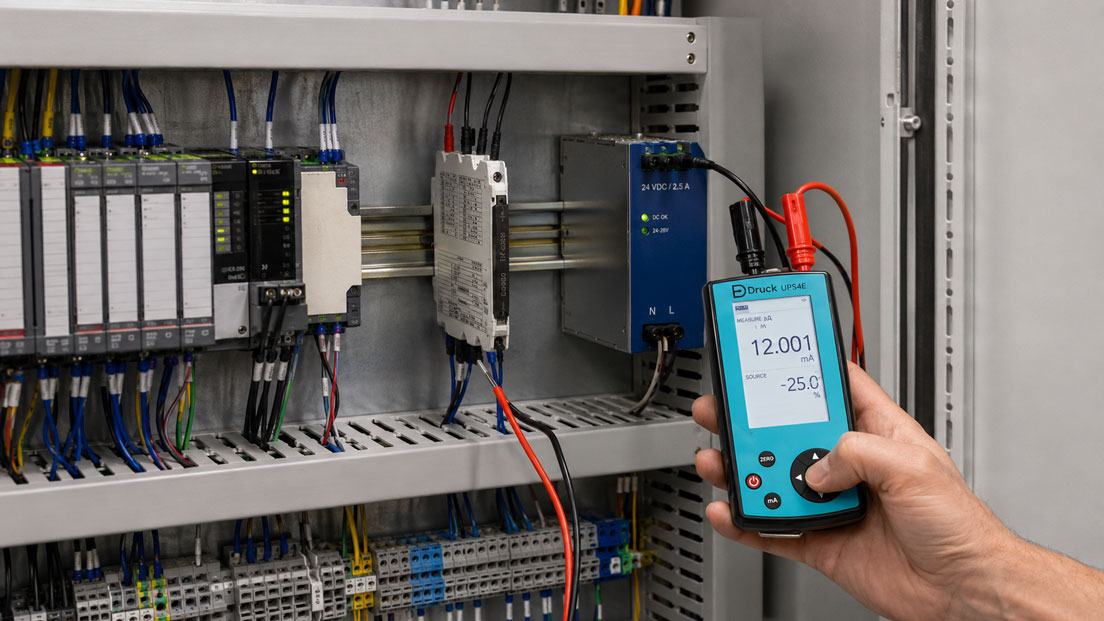
UPS4E loop calibrator
The UPS4E loop calibrator is suitable for commissioning and troubleshooting 4–20 mA measuring chains.
The device can measure current signals or generate defined current values. It can also provide a 24 V loop supply for passive measuring circuits.
This allows the transmitter and PLC to be tested independently:
- measure the converter output current
- simulate 4 mA, 12 mA and 20 mA at the PLC
- supply passive current loops
- check scaling and alarm limits
ICS Schneider Messtechnik assists with the selection of signal converters, isolation amplifiers and test equipment. The input and output signals, supply voltage, load resistance, isolation requirements and installation situation are required for a technical assessment.
Conclusion: Signal conversion must match the complete measuring chain
A transmitter enables the reliable integration of a 0–10 V signal into a 4–20 mA system. Conversion is particularly useful for retrofit projects, longer cable runs and incompatible PLC standards.
The specification “0–10 V to 4–20 mA” alone is not sufficient. The active or passive output, supply voltage, load resistance, galvanic isolation and response time must also match the application.
Correct scaling usually maps 0 V to 4 mA and 10 V to 20 mA. The sensor, converter and PLC must use the same measuring-range limits.
During commissioning, the zero point, midpoint and full-scale value should be checked separately. A loop calibrator can be used to determine whether a fault originates from the sensor, signal converter, current loop or PLC input.
Carefully planned signal conversion improves the compatibility, diagnostic capability and interference immunity of the installation and prevents errors that would otherwise only become noticeable as an apparently incorrect process value.
Frequently asked questions about converting 0–10 V to 4–20 mA
Can 0–10 V be connected directly to a 4–20 mA input?
No. A voltage output and a current input use different signal principles. A suitable signal converter is required.
How is 0–10 V scaled to 4–20 mA?
Typically, 0 V corresponds to 4 mA, 5 V corresponds to 12 mA and 10 V corresponds to 20 mA.
Why does the current signal begin at 4 mA?
The elevated zero point makes it easier to distinguish between a genuine lower-range value and a cable or power-supply failure.
Why is 4–20 mA suitable for long cables?
The measured value is represented by the loop current. Cable resistance is less critical within the permissible total load than with pure voltage transmission.
What does load resistance mean?
The load resistance is the total resistance against which the current output must operate. It includes the PLC input, cable and any other devices connected in series.
What happens if the load resistance is too high?
The transmitter can no longer provide the full required current. The output then remains below 20 mA, particularly at the upper end of the measuring range.
When is galvanic isolation required?
It is useful with different earth potentials, ground loops, electrically noisy plant areas or when electrical decoupling is required.
What is an active 4–20 mA output?
An active output generally provides the loop current itself. It is connected to a suitable passive input.
What is a passive current output?
A passive output requires an external loop supply. The exact wiring is defined by the manufacturer’s connection diagram.
Can a 4–20 mA signal be distributed to several PLC inputs?
Not arbitrarily. A series connection increases the load resistance and can cause potential problems. A suitable signal splitter should be used for several isolated outputs.
How is the signal conversion tested?
Defined voltages are applied to the input and the corresponding current values are measured at the output. At least 0 V, 5 V and 10 V should be tested.
What is a loop calibrator used for?
It can measure or simulate 4–20 mA signals and helps test the transmitter, wiring and PLC input independently of one another.