


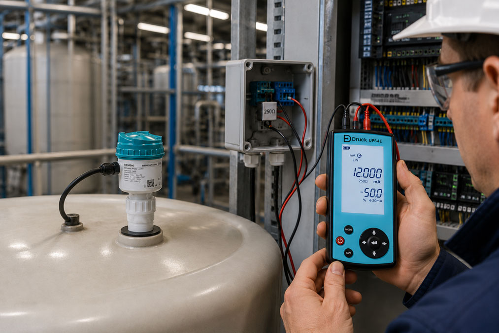
When selecting a level sensor, the measuring principle is usually the primary consideration. Depending on the application, possible options include a hydrostatic submersible probe, radar level sensor, ultrasonic measurement, guided-wave radar or a magnetostrictive float transmitter.
However, the way in which the measured value is transmitted to the PLC, process control system or machine controller is equally important for the subsequent operation of the measuring point. A sensor with the correct measuring principle can still cause problems if its output signal, power supply, scaling or diagnostic functions do not match the existing automation system.
4–20 mA is particularly robust and suitable for conventional industrial and process installations. HART adds digital parameterisation and diagnostic capabilities to the analogue current loop. IO-Link is particularly relevant for compact sensors in machine automation and enables standardised digital communication via an IO-Link master.
Other options include Modbus, fieldbus systems or simple switching outputs. The most suitable version depends not only on the cable length, but also on the system structure, diagnostic requirements, interchangeability and existing control technology.
This article explains the differences between the various signals, how to scale the empty and full points correctly and which wiring and commissioning errors occur most frequently.
Table of contents
- Considering the measuring principle and output signal separately
- Comparison of 4–20 mA, HART, IO-Link and Modbus
- When 4–20 mA is the correct choice
- What HART additionally provides
- When IO-Link is useful
- Modbus and other bus systems
- Continuous measured value or switching output?
- Correctly scaling the empty and full points
- Distinguishing active and passive current loops
- Power supply, load resistance and cable length
- Evaluating fault signals and diagnostics
- Systematically commissioning the measuring chain
- Loop check using a loop calibrator
- Typical parameterisation and connection errors
- Practical example: Radar sensor in a storage tank
- Which measuring instruments / products are suitable?
- Conclusion
- Frequently asked questions about level signals
Considering the measuring principle and output signal separately
The measuring principle determines whether the level can be measured reliably under the existing process conditions. The output signal, on the other hand, determines how the measured value is processed further.
A hydrostatic submersible probe can, for example, provide a simple 4–20 mA signal. A radar sensor may have the same analogue output but additionally support parameterisation via HART. A compact sensor for a machine tank may instead transmit its measured value digitally via IO-Link.
Before selecting a product, two questions should therefore be answered separately:
- Which measuring principle is suitable for the medium, vessel and process conditions?
- Which interface is suitable for the PLC, control system and maintenance concept?
A digital signal does not improve an unsuitable measuring principle. Conversely, a reliable sensor can only be used to a limited extent if its output does not match the existing control system.
Comparison of 4–20 mA, HART, IO-Link and Modbus
| Signal | Strengths | Typical application | Important requirement |
|---|---|---|---|
| 4–20 mA | Robust, simple, interference-resistant and suitable for long cables | Process plants, tanks, water and wastewater applications | Suitable analogue input and sufficient loop voltage |
| 4–20 mA/HART | Analogue value plus digital parameterisation and diagnostics | Process industry, retrofit projects and demanding measuring points | HART communicator or modem and suitable loop impedance |
| IO-Link | Digital measured values, diagnostics and simple device replacement | Machine building, skids and decentralised automation | IO-Link master and suitable device description |
| Modbus RTU | Several devices and measured values over one bus | Buildings, water technology, control cabinets and IIoT gateways | Correct addresses, baud rate, termination and bus structure |
| Switching output | Simple point-level indication | Overfill protection, dry-running protection and pump control | Correct assignment of PNP, NPN, relay or NAMUR output |
The decision should not be based on which signal is technically the most modern. The decisive factors are which data is actually required and which infrastructure is already available.
When 4–20 mA is the correct choice
The 4–20 mA signal remains one of the most important standards in process measurement technology. Typically, 4 mA corresponds to the lower and 20 mA to the upper end of the configured measuring range.
Current transmission is comparatively insensitive to the resistance of long cables. The prerequisite is that the power supply provides sufficient reserve to supply the sensor, cable and input resistance of the PLC.
4–20 mA is particularly suitable when:
- an existing PLC has a conventional analogue input
- the measuring point is located far from the control cabinet
- simple, manufacturer-independent integration is required
- only one continuous process value is required
- an existing system is to be retained as part of a retrofit project
The elevated zero signal of 4 mA facilitates fault detection. A current of 0 mA is not a valid lower measured value and normally indicates an interrupted loop, missing power supply or device fault.
The disadvantage is that a single analogue channel normally transmits only one scaled primary measured value. Additional information such as sensor temperature, echo quality or diagnostic status is not available without additional communication.
What HART additionally provides
HART combines a conventional 4–20 mA signal with digital communication on the same two-wire cable. The analogue current can still be evaluated by the existing PLC, while a HART communicator or corresponding input card retrieves additional information.
Depending on the sensor, HART can be used to configure or read parameters such as:
- lower and upper range values
- unit and damping
- distance, level, ullage or volume
- diagnostic and device status
- temperature or signal quality
- device identification and serial number
HART is particularly useful when existing 4–20 mA wiring is to be retained while more convenient parameterisation and diagnostics are required.
The loop must have a suitable impedance for communication. A resistance of approximately 250 Ω is frequently required. This resistance must be included when calculating the maximum permissible load.
A frequent mistake is to install a HART-capable sensor but use only the analogue signal. The measuring point then functions, but the additional diagnostic capabilities remain unused.
When IO-Link is useful
IO-Link is a digital point-to-point communication system between a sensor and an IO-Link master. The connection is typically made using standard unshielded sensor cables and M12 connectors.
The process value is transmitted digitally. This eliminates conversion and scaling errors caused by an analogue PLC input.
Further advantages may include:
- central parameterisation via the control system
- transmission of additional diagnostic and status data
- automatic transfer of stored parameters when replacing the device
- unique device identification
- combined use of measured values and switching states
IO-Link is particularly suitable for machines, compact systems and modular skids with manageable cable lengths. An IO-Link master or corresponding PLC module is required.
For remote field devices in large process plants, a conventional 4–20 mA or fieldbus solution is often simpler. Cable length, network structure and explosion-protection requirements must therefore be considered during the planning stage.
When replacing a device, it must also be verified that the correct IODD file and parameter set are used. An incorrect configuration transferred automatically can produce an incorrect level value just as easily as manual misparameterisation.
Modbus and other bus systems
Modbus RTU via RS-485 is suitable when several measuring instruments are to be connected through a shared bus cable. In addition to the level, further process and diagnostic data can be transmitted.
For reliable communication, all participants must be configured correctly with regard to address, baud rate, parity and data format. A linear topology and suitable termination at both ends of the bus must also be observed.
In larger process plants, PROFIBUS PA, Foundation Fieldbus or PROFINET may be used as alternatives. These systems enable extensive device integration but require suitable network planning and engineering software.
For individual standard measuring points, a fieldbus is not automatically more economical than 4–20 mA. With a large number of devices and extensive diagnostic requirements, however, digital integration can reduce wiring and maintenance effort.
Continuous measured value or switching output?
A continuous level sensor transmits the current measured value over the entire measuring range. A point-level sensor, on the other hand, only indicates whether a defined point has been reached or fallen below.
A switching output is sufficient, for example, for:
- overfill alarm
- dry-running protection for a pump
- minimum or maximum indication
- enabling a filling process
Inventory management, continuous control and trend recording, however, require an analogue or digital signal containing the current measured value.
Some sensors provide both functions simultaneously. The continuous value can then be transmitted to the PLC while a separate output provides an independent limit indication.
The switching logic must be clearly defined. PNP and NPN outputs are not interchangeable. The normally open, normally closed and fault states must also match the control-system input.
Correctly scaling the empty and full points
For analogue level measurement, the sensor and PLC must use the same range limits. Frequently:
- 4 mA corresponds to empty or 0%
- 12 mA corresponds to 50%
- 20 mA corresponds to full or 100%
However, this assignment can intentionally be inverted or restricted to part of the range. A radar sensor may, for example, output 4 mA at a level of 0.5 m and 20 mA at a level of 4.5 m.
With radar sensors, a distinction must also be made between distance and level. The sensor initially measures the distance from its reference surface to the product surface. The PLC, however, often requires the calculated filling height.
With hydrostatic submersible probes, the level is calculated from the liquid pressure. If the density of the medium changes, the indicated level can change even though the actual liquid level remains the same.
A percentage display also does not automatically represent the vessel volume. Horizontal cylindrical tanks, conical vessels and tanks with varying cross-sections require volume linearisation.
During commissioning, at least the following values should therefore be documented:
- physical empty point
- physical full point
- output signal at both points
- unit and measuring range of the PLC
- vessel characteristic curve, where applicable
Distinguishing active and passive current loops
Many level transmitters are designed as two-wire devices. They require an external power supply and regulate the current between 4 and 20 mA within this loop.
Whether the supply is provided by the PLC input card or by a separate power supply depends on the input design.
Typical errors include:
- passive sensor without loop voltage
- two power sources in the same loop
- reversed polarity
- current output connected to a voltage input
- incorrectly connected common ground
The terms active and passive are not always used consistently in practice. The specific wiring diagrams of the sensor and PLC module are therefore always decisive.
Power supply, load resistance and cable length
The transmitter requires a certain minimum voltage for its electronics. The remaining voltage must be sufficient to drive the current through the cable, PLC input, isolating amplifier and, where applicable, the HART resistor.
The maximum possible total load can be calculated approximately as follows:
Maximum load = (supply voltage − minimum sensor voltage) ÷ 0.02 A
With a 24 V supply and a required minimum voltage of 12 V, for example, 12 V remains available for the load:
12 V ÷ 0.02 A = 600 Ω
The manufacturer’s specifications remain binding for the specific design. In explosion-protected circuits, isolating power supplies, safety barriers and their voltage drops must also be considered.
Different conditions apply to IO-Link. The cable must comply with the specifications of the IO-Link system and the connected master. For very long distances, decentralised masters or alternative communication solutions are often more suitable.
Evaluating fault signals and diagnostics
A measured value outside the normal 4–20 mA range may represent a defined fault condition. Depending on the sensor and parameterisation, currents below approximately 3.6 mA or above 21 mA may be used to indicate a fault.
The PLC must not simply limit such values to 0 or 100%. A separate diagnostic status should be generated instead.
Possible causes of faults include:
- missing or insufficient echo
- sensor outside the measuring range
- electronics or memory fault
- impermissible process temperature
- interrupted current loop
- internal diagnostic message
HART and IO-Link can usually provide more detailed information about the fault. With a purely analogue input, the PLC only recognises that the current is outside the valid measuring range.
Systematically commissioning the measuring chain
Reliable commissioning includes the sensor, wiring, input card and PLC scaling.
- Check the device version: Compare the output signal, power supply, measuring range and approvals with the order.
- Check the wiring: Verify the polarity, terminals and shield connection using the manufacturer’s documentation.
- Parameterise the sensor: Configure the empty point, full point, unit, damping and fault behaviour.
- Configure the PLC: Set the input to 4–20 mA, HART, IO-Link or the relevant bus system.
- Check the scaling: Compare the raw value, percentage value and displayed filling height.
- Test intermediate points: Check at least one intermediate value in addition to the empty and full points.
- Simulate a fault: Test a cable interruption or diagnostic state and verify the alarm response.
For radar and ultrasonic sensors, the echo or signal profile should also be evaluated. A plausible output current alone does not prove that the sensor is actually detecting the product surface rather than an agitator or internal vessel component.
Loop check using a loop calibrator
A loop calibrator can be used to divide the measuring chain into individual sections.
The output of the level sensor can first be measured directly. Defined values such as 4 mA, 12 mA and 20 mA can then be simulated at the PLC.
This makes it possible to determine clearly:
- Is the sensor providing the correct current?
- Is the current loop supplied with sufficient voltage?
- Is the PLC input processing the signal correctly?
- Is the software scaled correctly?
- Are the limits and alarms functioning correctly?
With a HART sensor, it must also be checked whether digital communication is possible via the existing loop. A switchable 250 Ω resistor can provide the impedance required for communication.
A loop check does not replace testing the actual measuring principle. It confirms the electrical signal transmission, but not the correct detection of the product surface or hydrostatic pressure.
Typical parameterisation and connection errors
| Error | Possible effect | Better approach |
|---|---|---|
| Sensor configured for distance, PLC scaled for filling height | The indication operates in the wrong direction | Define the measured variable and reference point clearly |
| 4–20 mA sensor configured on a 0–20 mA input | Systematic scaling error | Configure the PLC input correctly |
| Fault current limited to 0 or 100% | Device fault is displayed as a real level value | Evaluate signals outside the measuring range separately |
| HART resistor omitted from the load calculation | 20 mA cannot be reached reliably | Add all resistances in the current loop |
| IO-Link device operated only as a switching input | Measured value and diagnostics remain unused | Configure the port for IO-Link communication |
| Incorrect IO-Link parameter set transferred | Unsuitable switching points or scaling | Check the device type and parameter backup |
| Duplicate Modbus address assigned | Communication errors or alternating data | Assign a unique address to every participant |
| Only the electrical loop tested | Incorrect sensor position or false echo remains undetected | Combine electrical and process-related testing |
Practical example: Radar sensor in a storage tank
A new radar sensor is to be installed on a five-metre-high storage tank and connected to an existing PLC. The control system has an available 4–20 mA input but does not support HART.
The sensor is configured with the following values:
- 4 mA corresponds to a filling height of 0.3 m
- 20 mA corresponds to a filling height of 4.7 m
- fault signal above the normal measuring range
After commissioning, the PLC indicates only approximately 35% when the tank is half full. The sensor output current measured directly is plausible.
When the PLC parameterisation is checked, it is found that a range of 0 to 5 m has been entered instead of 0.3 to 4.7 m. The electrical measuring chain is functioning correctly, but the sensor and PLC are using different range limits.
After correcting the scaling, the sensor display, PLC value and manual reference measurement agree.
A HART access point is additionally provided in the control cabinet for future maintenance work. This allows diagnostic information to be read even though the PLC continues to process only the analogue 4–20 mA signal.
The example shows that an incorrect level value is not necessarily caused by the sensor. The fault is frequently located in the scaling or signal processing.
Which measuring instruments / products are suitable?
The level sensors, level transmitters and submersible probes category contains different measuring principles and output signals for tanks, basins, shafts and process vessels.
Additional continuous measuring systems, point-level switches, indicators and accessories can be found in the level measurement technology category.
SITRANS LH100 for simple 4–20 mA measuring points
The SITRANS LH100 is a hydrostatic submersible probe for continuous level measurement in open tanks, basins, channels and wells.
It converts the hydrostatic pressure into a 4–20 mA signal and is particularly suitable for conventional PLC measuring points requiring straightforward analogue integration.
SITRANS Probe LU240 with HART
The SITRANS Probe LU240 is a compact ultrasonic level transmitter with a 4–20 mA output and HART communication.
HART enables parameterisation and diagnostics in addition to the continuously available analogue process value.
WIKA FLM-CA with 4–20 mA or HART
The WIKA FLM-CA measures the level of liquids using a magnetic float and the magnetostrictive measuring principle.
The device provides a 4–20 mA signal and is optionally available with HART. It is suitable for high-resolution continuous level measurement in industrial vessels.
SITRANS LT500 for evaluation and system integration
The SITRANS LT500 can evaluate level sensors with a 4–20 mA signal and, depending on the version, provides additional pump, relay, diagnostic and communication functions.
Optional interfaces such as HART, Modbus RTU and PROFINET enable connection to different automation structures.
UPS4E loop calibrator
The UPS4E loop calibrator is suitable for commissioning, loop checks and troubleshooting on 4–20 mA level measuring points.
The device can measure and simulate current signals and supply passive measuring circuits using an internal 24 V loop supply. The integrated 250 Ω resistor supports the creation of a suitable HART communication loop.
ICS Schneider Messtechnik assists with selecting the measuring principle, output signal and evaluation device. The medium, vessel geometry, measuring range, installation situation, existing control system, cable length and required diagnostic functions are needed for the design.
Conclusion: The correct signal must match the complete automation structure
Selecting a level sensor does not end with the measuring principle. The output signal, power supply, scaling and diagnostics determine how reliably the device can be integrated into a PLC or process control system.
4–20 mA is robust, simple and particularly suitable for existing process plants. HART supplements this proven current loop with digital parameterisation and diagnostics without eliminating the analogue primary measured value.
IO-Link offers advantages in machines and modular systems when digital measured values, central parameterisation and simple device replacement are required. Modbus and other bus systems are useful when several devices and additional values are to be transmitted over a shared communication network.
Particular attention must be paid to the empty and full points. The sensor and PLC must use the same range limits, units and reference directions. Irregular vessels additionally require correct volume linearisation.
Complete commissioning includes both the electrical measuring chain and the actual measuring principle. A loop calibrator can be used to verify whether the sensor, cable, analogue input and PLC scaling work together correctly.
The best interface is therefore not necessarily the most modern one, but the one that matches the application, existing infrastructure and required diagnostic capability.
Frequently asked questions about level signals
Which signal is the simplest for a level sensor?
For a conventional PLC measuring point, 4–20 mA is usually the simplest and most robust solution.
What is the difference between 4–20 mA and HART?
HART continues to use the analogue 4–20 mA signal but supplements it with digital communication for parameterisation and diagnostics.
Does HART require an additional cable?
No. The digital communication is superimposed on the same two-wire cable as the 4–20 mA signal.
Can a HART sensor be operated on a normal analogue input?
Yes. The analogue input continues to process the 4–20 mA value. Without an additional HART interface, however, digital diagnostic data cannot be read.
When should IO-Link be selected?
IO-Link is particularly suitable for machines and modular systems when digital process values, diagnostics and central parameterisation are required.
Can an IO-Link sensor be connected directly to a normal digital input?
Some devices additionally provide a switching mode. However, an IO-Link master is required for full IO-Link communication.
What does 4 mA mean on a level sensor?
4 mA normally corresponds to the configured lower end of the measuring range, frequently an empty vessel. The exact assignment must be checked in the parameterisation.
Why does the PLC display a different level from the sensor?
The sensor and PLC frequently use different measuring ranges, units or reference directions. An incorrectly configured analogue input may also be the cause.
How is a 4–20 mA level sensor tested?
The output current is measured and the PLC is then simulated using defined values such as 4, 12 and 20 mA. This allows sensor and control-system faults to be distinguished from one another.
Can a signal outside 4–20 mA indicate a fault?
Yes. Many sensors use defined underrange or overrange currents to indicate a device or process fault. The PLC should evaluate these values separately.
Is a switching output sufficient?
It may be sufficient for a simple full, empty or point-level indication. A measured-value signal is required for continuous indication, control or inventory management.
Which information does ICS Schneider require for selection?
The medium, vessel shape, measuring range, process conditions, existing PLC, required signal, cable length, power supply and diagnostic and alarm requirements are needed.