


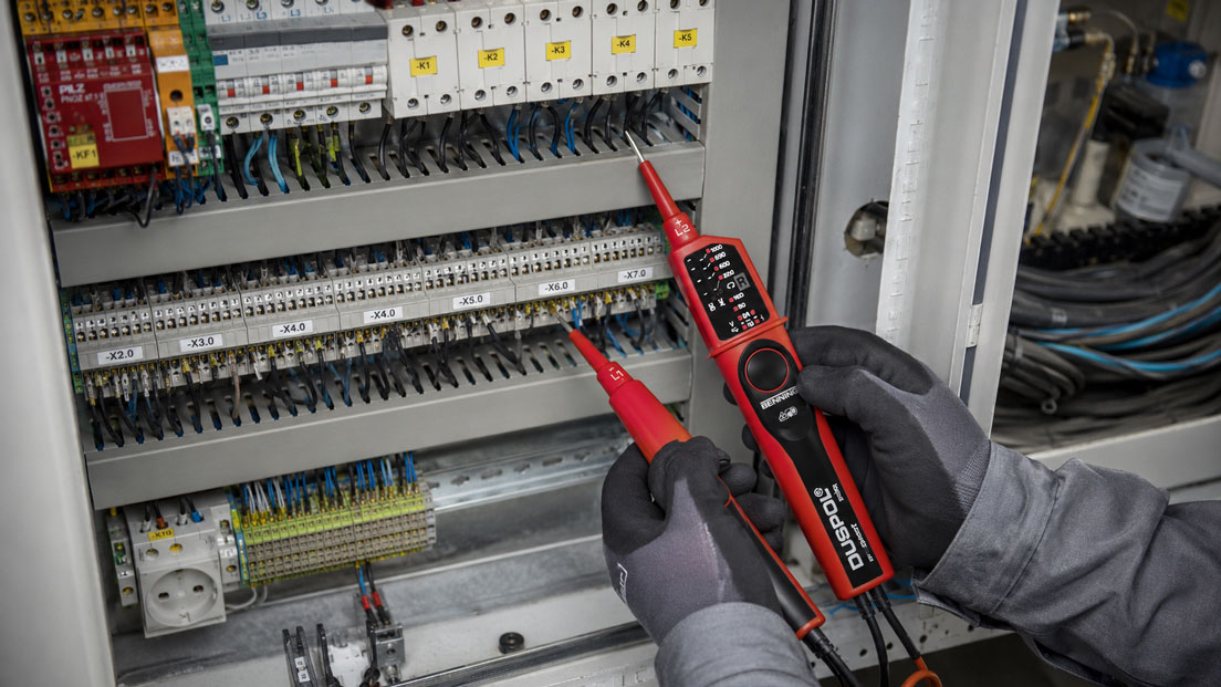
Two-pole voltage testers are primarily used to detect electrical voltages and verify that an installation is de-energised. Many models additionally feature optical and acoustic continuity testing.
The integrated buzzer makes it easier to check cables, fuses, switches and contacts quickly. During the test, the user does not have to keep looking at a display, but receives an immediate acoustic signal as soon as the electrical resistance between the test probes falls below the device-specific threshold.
However, an acoustic signal only means that a conductive path has been detected. It does not confirm a resistance close to zero ohms or that the connection has sufficient current-carrying capacity. Parallel current paths, connected loads, electronic components or contaminated contacts can lead to misinterpretations.
This article explains when the continuity-testing function of a voltage tester is useful for troubleshooting, where its limitations lie and when a multimeter or specialised installation tester is required instead.
Table of contents
- How continuity testing works
- Only test when the circuit is safely de-energised
- Advantages of the acoustic signal
- Identifying cables and conductors
- Checking fuses
- Testing switches, push-buttons and relay contacts
- Assessing terminals and plug connections
- Typical misinterpretations
- Limitations compared with multimeters and ohmmeters
- Why the function does not replace protective-conductor testing
- Systematic troubleshooting in a control cabinet
- Practical example: Finding an interrupted control cable
- Typical application errors
- Which measuring instruments / products are suitable?
- Conclusion
- Frequently asked questions about continuity testing
How continuity testing works
During continuity testing, the test instrument applies a small internal test voltage between the two probes. It then evaluates whether a sufficiently high test current flows through the connected circuit or whether the measured resistance lies below a defined threshold.
If the value falls below this threshold, the device activates, depending on its design:
- an acoustic buzzer
- an LED or symbol
- a combination of acoustic and optical indication
The resistance threshold is not the same for every voltage tester. One device may produce a signal at a comparatively high resistance, while another only recognises very low-resistance connections as continuity.
The acoustic signal must therefore not be interpreted as meaning that the connection is fault-free. Initially, it only means:
A conductive path recognised by the instrument exists between the two test points.
Only test when the circuit is safely de-energised
A conventional continuity or resistance test is always performed on a de-energised circuit. Before testing, the relevant part of the installation must be disconnected, secured against being switched on again and verified as de-energised using a suitable two-pole voltage tester.
The following additional measures may also be required:
- discharge capacitors and DC-link circuits in a controlled manner
- take stored mechanical or electrical energy into account
- exclude external and backfeed voltages from other circuits
- consider UPS systems, variable-frequency drives and decentralised power supplies
Before and after voltage testing, the voltage tester should be checked for correct operation using a known voltage source or a suitable proving unit.
Some specialised voltage testers have additional functions which, according to the manufacturer, may also be used under certain voltage conditions. Such special functions may only be used in accordance with the operating instructions for the specific instrument. General continuity testing on an unknown circuit that may be energised is not permitted.
Advantages of the acoustic signal
The acoustic buzzer is particularly helpful for repeated tests and tests at locations that are difficult to see. The user can concentrate on positioning the probes and does not have to look at a display or LED for every contact.
This is helpful, for example:
- on densely populated terminal blocks
- when testing multicore cables
- on switches and plug connections that are difficult to access
- when searching for a cable interruption
- when checking several fuses
In a noisy industrial environment, however, a quiet buzzer may be overlooked. An additional optical indication is therefore useful. Before starting work, it should be checked whether the acoustic signal can be heard clearly under the actual environmental conditions.
Identifying cables and conductors
Continuity testing can be used to assign the two ends of a cable to one another. One conductor at one end of the cable is contacted with a probe, and the corresponding conductor is then located at the other end.
For an unambiguous result, the conductors being tested should be disconnected from connected devices, terminal bridges and other current paths.
If the cable remains connected within a fully wired installation, the test current may return through components such as:
- contactor or relay coils
- indicator lamps
- power supplies and electronic inputs
- shared neutral or ground connections
- contacts connected in parallel
The voltage tester may then indicate continuity even though the conductor being searched for is not connected directly to the suspected opposite end.
With long cables, attention should also not be paid only to the first brief acoustic signal. Cable capacitance and connected interference-suppression components can be charged briefly when the test voltage is applied and may therefore cause a temporary acoustic signal.
Checking fuses
After removal, a fuse can be checked quickly for continuity. A continuous acoustic signal indicates that the fuse element is not completely interrupted.
This test is particularly useful when the defect cannot be seen from the outside.
A fuse that remains installed in the circuit must be assessed with caution. Loads connected in parallel or backfeed paths can create a conductive path around the fuse. The test instrument may then indicate continuity even though the fuse itself is defective.
For an unambiguous result, the fuse should therefore be disconnected on at least one side or removed completely.
An acoustic signal also provides no information about:
- the rated current of the fuse
- the correct tripping characteristic
- thermal pre-damage
- the condition of the fuse holder
Testing switches, push-buttons and relay contacts
For a mechanical switch, continuity testing can show whether the contact opens or closes when operated.
A normally open contact should show no continuity in the normal state and continuity when actuated. The behaviour is reversed for a normally closed contact.
The method is also suitable for:
- limit switches
- emergency-stop auxiliary contacts
- pressure and temperature switches
- relay and contactor auxiliary contacts
- door and position contacts
The contacts being tested should be disconnected from the rest of the circuit. Otherwise, coils, indicator lamps or PLC inputs may create a parallel current path.
A contact may also still remain below the acoustic threshold even though its contact resistance is already too high for the subsequent load current. Assessing loaded power contacts may therefore require a resistance or voltage-drop measurement under suitable test conditions.
Assessing terminals and plug connections
Continuity testing can be used to establish whether two terminals or plug contacts are electrically connected. It is suitable, for example, for checking newly installed control wiring.
However, the acoustic signal does not confirm that a connection is mechanically secure and permanently capable of carrying the required load.
A loose screw terminal may briefly make contact when touched by the probe and produce an acoustic signal. Under operating current, however, the connection may still have an increased contact resistance, become hot or cause intermittent failures.
The following checks therefore remain necessary in addition to the electrical test:
- visual inspection of the conductors and ferrules
- verification of the correct terminal point
- checking the specified tightening condition or spring contact
- performing a pull test in accordance with company requirements
Typical misinterpretations
An unexpected acoustic signal is often interpreted prematurely as a short circuit. In reality, many components can permit a limited current flow.
| Cause | Possible behaviour | Assessment |
|---|---|---|
| Relay or contactor coil | Continuous acoustic signal possible | Conductive coil path, not automatically a short circuit |
| Capacitor | Brief acoustic signal that then stops | Capacitor charging process |
| Diode or LED | Continuity may be indicated in only one direction | Take semiconductor behaviour into account |
| Load connected in parallel | Signal despite interrupted main cable | Current flows through an alternative path |
| Moisture or contamination | Unstable or unexpected acoustic signal | Leakage current or conductive deposits |
| Corroded contact | Acoustic signal despite increased contact resistance | Accurate resistance measurement required |
To narrow down the cause, the component being tested can be disconnected from the circuit step by step. This makes it possible to determine whether continuity exists directly through the component or through a parallel path.
Limitations compared with multimeters and ohmmeters
The continuity function of a voltage tester is designed for a quick yes-or-no decision. It often does not provide an exact resistance value.
A multimeter is more suitable when it is necessary to determine:
- the actual resistance value
- whether contact resistance changes slowly
- whether a coil has the expected resistance
- whether a diode behaves correctly in the forward and reverse directions
- whether a temperature sensor or resistance transducer is plausible
The resistance measurement of a multimeter can also be distorted by components connected in parallel. For an unambiguous result, the component being tested may need to be disconnected from the circuit on at least one side.
Very low contact resistances can only be assessed to a limited extent using a conventional two-wire measurement because the test leads and contact points also contribute to the result. A dedicated micro-ohmmeter using four-wire technology may be required for demanding low-resistance measurements.
Why the function does not replace protective-conductor testing
During an indicative check, the buzzer of a voltage tester can show whether a conductive connection generally exists between two points.
However, it does not replace standard-compliant testing of protective conductors, earthing conductors or equipotential-bonding conductors.
Suitable resistance measuring instruments or installation testers are used for these tests. They operate under defined test conditions and allow a quantitative assessment of the connection.
A simple acoustic signal cannot reliably establish, for example, whether:
- the resistance is appropriate for the conductor cross-section and length
- the connection can safely carry the required test current
- an increased contact resistance is present
- the complete protective measure is effective
The continuity function of the voltage tester is therefore a tool for troubleshooting and preliminary checks, not for complete testing of electrical protective measures.
Systematic troubleshooting in a control cabinet
If a control function is interrupted, every terminal should not be tested at random. A step-by-step approach reduces troubleshooting time.
- Check the circuit diagram: Identify the affected current path, terminals and contacts.
- Disconnect the installation safely: Take all possible power supplies into account.
- Verify that the circuit is de-energised: Use a suitable two-pole voltage tester.
- Check the test instrument: Bring the probes together and verify the acoustic and optical indication.
- Divide the current path: First test larger sections and then individual cables or contacts.
- Consider parallel paths: Disconnect components on one side if the results are unclear.
- Confirm the fault location: Measure the resistance with a multimeter where necessary.
- Test again after the repair: Check the wiring, protective measures and function.
Testing the circuit section by section allows an interruption to be narrowed down more quickly than checking every individual terminal directly.
Practical example: Finding an interrupted control cable
In a control cabinet, a contactor does not energise despite the control voltage being present. An initial check indicates that the coil and the PLC output card are functioning correctly.
The affected control circuit is safely disconnected and verified as de-energised. The current path is then divided into several sections using the circuit diagram.
The continuity test between the PLC terminal and the intermediate terminal produces an acoustic signal. The section between the safety contact and the contactor coil also has continuity.
However, no acoustic signal is produced between two terminals of a remote machine cable. The cable is disconnected at both ends and each conductor is tested individually.
No connection is detected on one conductor. A visual inspection of the plug connector shows that the conductor has been inserted into the housing, but the crimp contact has not fully engaged.
After the fault is repaired correctly, permanent continuity is present. The wiring and electrical function are then tested again.
The example demonstrates the advantage of the buzzer: The technician can concentrate on the probes, terminals and circuit diagram and immediately recognise the transition between a conductive and interrupted section.
Typical application errors
| Error | Possible consequence | Better approach |
|---|---|---|
| Continuity test performed without a prior voltage test | Hazard and possible damage to the test instrument | Disconnect the circuit and verify that it is de-energised |
| Acoustic signal interpreted as proof of zero ohms | Increased contact resistance remains undetected | Measure the exact resistance where required |
| Component tested within a fully wired circuit | Parallel paths distort the result | Disconnect the component on at least one side |
| Fuse tested only while installed | Loads connected in parallel simulate continuity | Remove or clearly isolate the fuse |
| Brief acoustic signal interpreted as permanent continuity | Capacitor charging is misinterpreted | Take the signal behaviour and connected electronics into account |
| Buzzer used for protective-conductor acceptance testing | Inadequate assessment of the protective measure | Use a suitable installation tester |
Which measuring instruments / products are suitable?
The voltage testers and meter-starting testers category contains various two-pole voltage testers for electrical installation, maintenance, industry and energy supply.
Additional multimeters, installation testers and test instruments are available in the electrical measuring and test instruments category.
DUSPOL expert
The DUSPOL expert provides optical and acoustic continuity testing using an LED and buzzer.
It is particularly suitable for quick tests on cables, fuses, switches and contacts. Additional functions include voltage testing, phase-sequence indication, measuring-point illumination, load connection and a non-contact cable-break detector.
DUSPOL digital
The DUSPOL digital combines the functions of the DUSPOL expert with a digital display and resistance, frequency and diode measurement.
The instrument is therefore advantageous when a resistance value or the behaviour of a semiconductor component must also be assessed after an acoustic continuity check.
C.A 771
The C.A 771 is a robust two-pole voltage tester with optical and acoustic continuity testing. The buzzer indicates a resistance below 100 Ω. Additional resistance ranges can be displayed optically.
The device is therefore suitable both for quick continuity checks and for a graduated assessment of conductive connections.
HT8
The HT8 provides acoustic and optical continuity testing as well as a digital voltage display.
It is designed for typical test and service work in the electrical trade and industrial installations and additionally supports polarity and phase-sequence testing.
Selecting the appropriate test instrument
For quick checks of cables and contacts, a voltage tester with a clearly audible buzzer and unambiguous LED indication is often sufficient.
If resistance, diodes or frequencies also need to be measured, a model with a digital measured-value display is useful. Standard-compliant installation, protective-conductor or insulation testing, however, requires an installation tester designed for these tasks.
ICS Schneider Messtechnik assists with selecting a voltage tester suited to the voltage range, measurement category, continuity function, load connection and other required test tasks.
Conclusion: The buzzer accelerates troubleshooting but does not replace accurate measurement
Acoustic continuity testing is a practical additional function of a two-pole voltage tester. It facilitates quick checks of cables, fuses, switches, relay contacts and plug connections.
However, the acoustic signal merely indicates that the resistance is below the device-specific switching threshold. It confirms neither a low-resistance connection nor the electrical and mechanical current-carrying capacity of a contact.
Parallel current paths, coils, capacitors and electronic components can cause apparent or temporary continuity. If the result is unclear, the component should be disconnected from the rest of the circuit and its resistance determined using a suitable measuring instrument.
The safe working procedure is particularly important: A conventional continuity test is only performed after disconnecting the circuit and reliably verifying that it is de-energised.
Used correctly, the acoustic buzzer considerably reduces troubleshooting time. However, multimeters, micro-ohmmeters or installation testers remain necessary for accurate resistance measurements and the testing of electrical protective measures.
Frequently asked questions about continuity testing
What does an acoustic signal mean during continuity testing?
The resistance between the test probes is below the switching threshold defined by the manufacturer. The exact resistance value cannot automatically be determined from this.
May continuity testing be performed on an energised circuit?
A conventional continuity test is only performed when the circuit has been safely verified as de-energised. Different special functions may only be used in accordance with the operating instructions for the respective instrument.
Can a fuse be tested while installed?
The result may be distorted by parallel current paths. For an unambiguous test, the fuse should be removed or disconnected on at least one side.
Why does the buzzer sound only briefly?
One possible cause is the charging of a capacitor. Electronic circuits may also cause a brief test current.
Why does the buzzer sound when testing a relay coil?
The coil has a finite resistance and therefore forms a conductive current path. This does not mean that a short circuit is present.
Can a voltage tester be used to find a cable break?
On de-energised and disconnected cables, the interruption can be narrowed down through section-by-section continuity testing. Some instruments additionally have a special non-contact cable-break function.
Is the acoustic signal sufficient for checking a protective conductor?
No. Standard-compliant assessment of protective and equipotential-bonding conductors requires a resistance or installation tester designed for this purpose.
What is the difference compared with resistance measurement?
Continuity testing primarily provides a yes-or-no indication. Resistance measurement provides a specific measured value in ohms.
Why does the device indicate continuity even though the switch is open?
A parallel current path may exist through a coil, lamp, electronic circuit or another connected component.
Which voltage tester is suitable for continuity testing?
A suitable instrument is a two-pole voltage tester with a clearly audible buzzer, an unambiguous optical indication and a measurement category appropriate for the installation. A device with a digital display is advantageous for additional resistance measurements.