


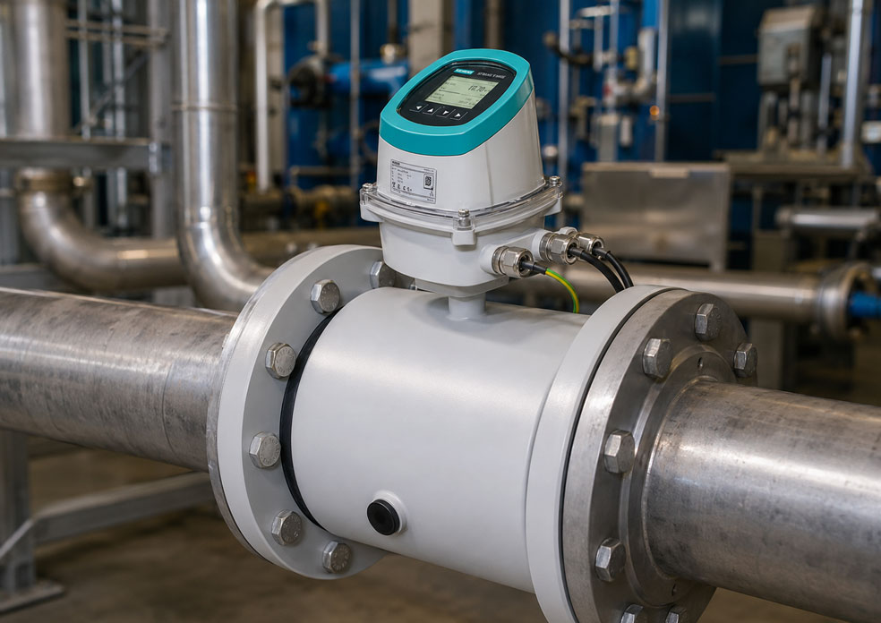
Electromagnetic flowmeters are regarded as robust and low-maintenance measuring instruments for electrically conductive liquids. They have no moving parts within the flow cross-section, cause only a small additional pressure loss and, depending on the liner and electrode material, can be used for water, wastewater, chemicals, slurries and numerous process media.
Nevertheless, electromagnetic flowmeter measuring points sometimes exhibit fluctuating flow values, an unstable zero point or an apparent flow when the liquid is stationary. In such cases, the transmitter, parameter settings or calibration are often suspected first. However, the actual cause is frequently missing or unsuitable equipotential bonding.
An electromagnetic flowmeter evaluates a very small electrical voltage between its measuring electrodes. For this signal to be reliably detected, the medium, sensor and transmitter must have a defined electrical reference potential. If uncontrolled potential differences arise between the pipeline, liquid and measuring instrument, interference voltages can be superimposed on the actual flow signal.
This problem occurs particularly frequently with plastic pipes, internally coated metal pipes, insulating flange gaskets, cathodically protected pipelines and remotely mounted transmitters. Variable-frequency drives, motor cables, pumps and incorrectly connected cable shields can also cause additional interference.
Grounding rings, integrated grounding electrodes and equipotential bonding straps perform different but related functions. They establish a defined electrical contact with the medium, equalise potential differences and divert interference currents as far as possible outside the sensitive measuring section.
However, there is no universal standard solution for every electromagnetic flowmeter. The correct design depends on the measuring instrument, pipe material, liner, medium, explosion protection, any cathodic protection system and the manufacturer’s specifications.
This article explains the measuring principle of an electromagnetic flowmeter, the purpose of equipotential bonding and the differences between metal pipes, plastic pipes and lined pipes. It also shows when grounding rings are required, which errors can occur in cable shielding and EMC installation and how an unstable measuring point can be investigated systematically.
Table of contents
- Why grounding influences the measurement of an electromagnetic flowmeter
- How an electromagnetic flowmeter works
- Why the medium must be electrically conductive
- How small the electrical measuring signal is
- What equipotential bonding means for an electromagnetic flowmeter
- Distinguishing protective earthing from functional earthing
- How interference voltages affect flow measurement
- Grounding an electromagnetic flowmeter in metal pipelines
- Grounding an electromagnetic flowmeter in plastic pipes
- Correctly assessing internally lined metal pipes
- Purpose and construction of grounding rings
- Integrated grounding electrode or grounding ring?
- Selecting the material of the grounding rings
- Installing grounding rings correctly
- Flange gaskets and insulating coatings
- Cathodically protected pipelines
- Equipotential bonding in hazardous areas
- Compact and remote electromagnetic flowmeter designs
- Cable shielding with a remotely mounted transmitter
- EMC, variable-frequency drives and motor cables
- 4–20 mA, pulse and digital outputs
- Ensuring a completely filled measuring tube
- Installation position of the measuring electrodes
- Deposits and electrode coatings
- Low conductivity and unstable measured values
- Correctly assessing the zero point and low flow rates
- Systematic troubleshooting of unstable electromagnetic flowmeter readings
- Which electrical tests are useful
- Typical grounding and installation errors
- Practical example: Fluctuating electromagnetic flowmeter in a plastic pipeline
- Which information is required for the design
- Which measuring instruments / products are suitable?
- Conclusion
- Frequently asked questions about grounding electromagnetic flowmeters
Why grounding influences the measurement of an electromagnetic flowmeter
With many electrical devices, grounding is primarily understood as a protective measure. A metal housing is connected to the protective conductor so that, in the event of a fault, a dangerous touch current is discharged and the protective device is activated.
With an electromagnetic flowmeter, there is also a metrological function. The liquid inside the measuring tube must have a defined electrical reference potential in relation to the measuring electronics.
If this reference potential is missing, the electrical potential of the liquid can shift in relation to the sensor. Possible causes include pumps, friction within the pipeline, different materials, static charging, variable-frequency drives, welding equipment, leakage currents or potential differences between different parts of the installation.
The measuring electrodes then detect not only the useful voltage generated by the flow. They also detect unwanted DC and AC voltage components. Although the transmitter attempts to suppress many of these influences through signal processing and filtering, it cannot fully compensate for fundamentally incorrect equipotential bonding.
Correct grounding therefore does not improve the factory calibration of the sensor. Instead, it creates the electrical conditions required for the calibrated measuring system to detect its actual useful signal with minimal interference.
How an electromagnetic flowmeter works
The measuring principle is based on Faraday’s law of induction. When an electrically conductive substance moves through a magnetic field, an electrical voltage is generated.
In an electromagnetic flowmeter, coils generate a magnetic field perpendicular to the direction of flow. The electrically conductive liquid moves through this field. Two opposing measuring electrodes detect the resulting voltage.
In simplified form:
U = k × B × D × v
Where:
- U is the voltage measured at the electrodes
- k is an instrument-specific factor
- B is the magnetic flux density
- D is the internal diameter of the measuring tube
- v is the average flow velocity
Because the cross-section and internal diameter of the sensor are known, the transmitter calculates the volumetric flow rate from the flow velocity.
The internal liner of the measuring tube electrically isolates the liquid from the metal sensor housing. This prevents the generated measuring signal from flowing away through the pipe wall and allows it to be detected by the measuring electrodes.
This necessary insulation also explains why a defined potential contact with the liquid must be established. Depending on the sensor design, this is achieved by integrated grounding electrodes or external grounding rings.
Why the medium must be electrically conductive
An electromagnetic flowmeter can only measure media with sufficient electrical conductivity. Typical measurable liquids include water, wastewater, acids, alkalis, conductive solutions, slurries and many water-based process media.
Pure hydrocarbons, oils, many solvents and demineralised liquids may be unsuitable depending on their conductivity.
The required minimum conductivity depends on the instrument. It must therefore be taken from the data sheet for the specific sensor and transmitter combination.
The lower the conductivity, the more sensitive the measurement may become to the condition of the electrodes, cable capacitance, moisture, interference voltages and unsuitable equipotential bonding.
A grounding ring cannot increase the conductivity of the medium. If the medium is below the permissible minimum conductivity, even perfect grounding will not automatically enable the electromagnetic flowmeter to measure reliably.
Before undertaking extensive troubleshooting, it should therefore be checked whether the composition, temperature and conductivity of the actual medium correspond to the instrument design.
How small the electrical measuring signal is
The voltage detected by the measuring electrodes is typically within a range in which electrical interference can become relevant.
An interfering potential difference of only a few millivolts may already be significantly greater than the useful voltage generated by a low flow velocity.
The measurement is therefore particularly sensitive:
- close to the zero point
- at low flow velocities
- with media of low conductivity
- with long electrode cables
- with damp or contaminated connection compartments
- in strong electromagnetic interference fields
- when the liquid potential is undefined
The output signal of the transmitter may be 4–20 mA, pulse, frequency or a digital communication signal. These outputs are considerably more robust than the original electrode signal.
A fluctuation at the 4–20 mA output may therefore already have originated in the sensor. Simply checking the current output then confirms the unstable signal, but does not yet reveal its cause.
What equipotential bonding means for an electromagnetic flowmeter
Equipotential bonding ensures that the medium, sensor and the designated electrical connection points are at a defined reference potential.
With a conductive metal pipeline, this reference potential can frequently be established using equipotential bonding straps between the sensor and the adjacent pipe flanges.
This electrical contact is missing with plastic pipes. An internally lined metal pipeline may also be electrically isolated from the liquid. In such cases, contact with the medium is frequently established using grounding rings or integrated grounding electrodes.
The measuring electrodes themselves should not be regarded as arbitrary grounding points. They are used to detect the measuring signal and form part of the sensitive input circuit.
Equipotential bonding should prevent interference currents from flowing through the measuring electrodes or the electrode signal. Instead, it should provide a defined low-impedance path through which potential differences can be equalised outside the actual measuring signal.
The specific wiring must always be taken from the operating instructions for the electromagnetic flowmeter being used. The term “grounding an electromagnetic flowmeter” must not result in all metal parts being connected arbitrarily to any available ground point.
Distinguishing protective earthing from functional earthing
Protective earthing and functional equipotential bonding may both be present on the same instrument, but they do not perform the same function.
| Connection | Main function | Typical connection point |
|---|---|---|
| Protective conductor / PE | Protection against dangerous touch voltages | Marked PE terminal on the transmitter or housing |
| Functional earth | EMC-compliant operation and discharge of electrical interference | Grounding or shield terminal specified by the manufacturer |
| Sensor equipotential bonding | Common reference potential for the liquid, sensor and pipeline | Grounding strap, grounding ring or integrated grounding electrode |
| Cable shield | Shielding of sensitive signal and coil cables | Defined shield terminal according to the wiring diagram |
A connected protective conductor at the transmitter does not automatically confirm that the liquid inside the measuring tube is correctly connected to the reference potential.
Conversely, a grounding ring at the process connection does not replace the required protective earthing of a mains-powered transmitter.
Errors frequently occur when all these concepts are grouped together under the term “ground” and cables are connected without observing the manufacturer’s wiring diagram.
How interference voltages affect flow measurement
Interference voltages may occur as DC voltage, AC voltage or pulse-shaped signals. Their influence on the electromagnetic flowmeter depends on their frequency and amplitude, the conductivity of the medium and the signal processing performed by the transmitter.
Possible symptoms include:
- fluctuating flow despite a steadily operating pump
- positive or negative flow with a closed valve
- sudden changes in the measured value when a motor is switched on
- an unstable zero point while a variable-frequency drive is operating
- sporadic empty-pipe alarms
- a strongly fluctuating 4–20 mA signal
- deviations occurring only at low flow velocities
- different behaviour when the pipeline system is touched or electrically connected
These symptoms do not yet prove that there is a grounding fault. Air bubbles, incomplete pipe filling, deposits, an unsuitable installation position or actual pulsations can produce similar effects.
Grounding is therefore an important part of the diagnosis, but it is not the only possible cause.
Grounding an electromagnetic flowmeter in metal pipelines
With an electrically conductive metal pipeline that is not internally insulated, the liquid potential can frequently be established through the pipeline itself.
The electromagnetic flowmeter is connected to the adjacent pipe flanges using equipotential bonding straps. The connection is normally made on both sides of the sensor.
The contact points must be electrically conductive. Paint, rust, plastic coatings, sealing compounds or heavily oxidised surfaces can impair the contact.
A mechanically secure bolted connection is therefore not automatically a reliable electrical connection.
During installation, it must be checked:
- whether the pipeline is actually electrically continuous
- whether the inner surface is electrically connected to the medium
- whether insulating intermediate sections are present
- whether the flanges are coated or painted
- whether flexible expansion joints interrupt the electrical path
- whether the manufacturer requires equipotential bonding straps on both sides
The design must not be based solely on general experience with electromagnetic flowmeters. Some sensors have integrated grounding electrodes and, depending on the application and pipeline system, do not require additional grounding rings. Equipotential bonding straps or the specified housing earth may nevertheless still be required.
Grounding an electromagnetic flowmeter in plastic pipes
Plastic pipes provide no electrically conductive contact between the liquid and the pipeline. The medium is therefore largely isolated from the plant potential.
Without an additional measure, the liquid potential can shift in relation to the sensor. Static and electrical potential differences may occur particularly in long plastic pipelines, at high flow velocities or in systems containing pumps.
For many electromagnetic flowmeter systems, grounding rings are therefore installed on the inlet and outlet sides of the sensor. The rings are positioned between the sensor flange and pipe flange and contact the liquid along their inner edge.
Grounding cables connect them to the designated connection points on the sensor or to the equipotential bonding system.
Depending on the manufacturer and application, a grounding ring on only one side may be insufficient. The arrangement must be taken from the operating instructions for the specific sensor.
If the sensor has integrated grounding electrodes, additional rings can be omitted in many applications. However, whether the integrated electrode is sufficient for the medium, pipe material and electrical structure of the installation must be checked for the specific model.
Correctly assessing internally lined metal pipes
A metal pipeline is useful for establishing the liquid potential only if the liquid is actually in electrical contact with the metal.
This contact is frequently absent in pipes that are internally rubber-lined, enamelled, plastic-coated or lined in another way.
From the electrical perspective of the medium, such a pipeline behaves similarly to a plastic pipe. The outer pipe wall may be connected to the protective equipotential bonding system, but the medium remains isolated from it by the internal liner.
In this situation, grounding rings, grounding electrodes or other contact surfaces specified by the manufacturer may be required.
Lined valves, expansion joints and intermediate sections must also be taken into account. A short metal pipe section is of no benefit if it is isolated from the rest of the system on both sides by insulating components.
Purpose and construction of grounding rings
A grounding ring is a conductive disc installed between the process flanges. The inner part of the ring is in contact with the medium.
This allows the ring to detect the liquid potential and connect it to the designated equipotential bonding system of the sensor.
Depending on the instrument manufacturer and design, grounding rings may perform different functions:
- establishing a defined liquid potential
- symmetrical equipotential bonding on both sides of the sensor
- diverting interference currents outside the measuring electrodes
- protecting the sensor liner against certain mechanical influences
- providing an additional process contact surface for special applications
Not every ring automatically performs all of these functions. Different designs are available, including narrow grounding rings, wider protection rings and special rings for abrasive media.
The dimensions must match the nominal diameter, flange standard, pressure rating and sensor liner.
An internal diameter that is too small can restrict the flow cross-section, cause deposits or mechanically load the liner. An incorrectly dimensioned outer diameter can prevent correct flange installation.
Integrated grounding electrode or grounding ring?
An integrated grounding electrode is located inside the sensor and establishes direct electrical contact with the liquid.
It must be distinguished from the actual measuring electrodes. The measuring electrodes detect the flow-dependent voltage, while the grounding electrode stabilises the reference potential.
The advantage of an integrated grounding electrode is that additional rings, sealing points and installation components can be omitted in many applications.
Whether a ring is nevertheless required depends, among other things, on:
- sensor design
- pipe material
- manufacturer specifications
- cathodic corrosion protection
- special interference-current conditions
- medium and material compatibility
- mechanical protection of the liner
The statement “the sensor has a grounding electrode” must therefore not automatically be interpreted as “no further grounding measures are required”.
The SITRANS FMS500, for example, has integrated grounding electrodes, which means that separate grounding rings are not required for many applications. The remaining electrical connections must nevertheless be made in accordance with the instrument instructions.
Selecting the material of the grounding rings
The grounding ring is permanently or regularly in contact with the process medium. Its material must therefore be selected at least as carefully as the material of the measuring electrodes.
Depending on the medium and sensor range, different stainless steels, Hastelloy, titanium, tantalum or other special materials may be available.
The selection depends, among other factors, on:
- chemical composition of the medium
- concentration
- temperature
- pressure
- flow velocity
- solids content or abrasiveness
- cleaning and flushing media
- possible galvanic material combinations
A grounding ring made from an unsuitable material may corrode, contaminate the medium or itself generate an additional electrochemical voltage.
Final media compatibility must be confirmed for the specific application by the operator or on the basis of binding manufacturer information. A general material table does not replace this assessment.
Installing grounding rings correctly
Grounding rings are normally installed together with the flange gaskets. The sequence specified by the manufacturer must be followed.
The ring must be centred and must not project into the flow cross-section. The gasket must not completely isolate the inner contact area of the ring from the medium.
Before tightening the flange bolts, it must be checked that the sensor, ring, gasket and pipe flange are concentrically aligned.
Uneven tightening can:
- damage the sensor liner
- deform the ring
- cause leakage
- offset the internal diameter
- impair the electrical contact
The flange bolts are tightened gradually and in a crosswise sequence in accordance with the manufacturer’s instructions. Permissible tightening torques depend on the nominal diameter, gasket, flange, liner and pressure rating.
The grounding cable must be mechanically secure and protected against corrosion. Loose cable lugs or painted contact points can cause a measuring point that initially operated correctly to become unstable later.
Flange gaskets and insulating coatings
Flange gaskets are required to seal the process connection. At the same time, they may interrupt the electrical contact between two metal flanges.
Electrical equipotential bonding must therefore not be assumed to take place solely through the flange bolts and sealing surfaces.
Bolts may also be electrically isolated by coatings, corrosion, insulating sleeves or washers.
During installation, a defined equipotential bonding path must be provided that operates independently of accidental metal-to-metal contact.
Particular attention is required with:
- plastic-coated flanges
- rubber gaskets
- insulating flange kits
- coated bolts
- flexible expansion joints
- liners extending over the flange face
Cathodically protected pipelines
Cathodic corrosion-protection systems deliberately apply electrical potentials or currents to a pipeline. An unsuitable grounding connection can impair this protective function or cause unwanted currents to flow through the electromagnetic flowmeter.
For a cathodically protected pipeline, the electromagnetic flowmeter must therefore not simply be connected to all adjacent pipe components and to the general earth.
Depending on the instrument and installation concept, the following may be required:
- electrical isolation of the sensor from the pipe flanges
- insulating sleeves and washers on the flange bolts
- a separate bypass cable for the cathodic protection current
- specially arranged grounding rings or electrodes
- galvanically isolated signal and supply paths
The bypass cable must be designed for the possible protection current and environmental conditions.
Such installations must be planned together with the instrument manufacturer and the person responsible for the cathodic corrosion-protection system. A standard drawing intended for conventional metal pipes must not be adopted without verification.
Equipotential bonding in hazardous areas
In hazardous areas, equipotential bonding is relevant not only to measurement stability, but also to explosion protection.
The external equipotential bonding terminal, protective earth, cable shields, intrinsically safe circuits and process connections must be implemented in accordance with the Ex approval and installation instructions.
Additional or different grounding connections may affect the intrinsic safety or galvanic isolation of a measuring circuit.
The following must be checked in particular:
- ATEX or IECEx version of the sensor and transmitter
- zone and equipment category or EPL
- designated equipotential bonding terminal
- permissible cables and cable entries
- shield connection within the Ex concept
- isolating barriers and galvanic isolation
- requirements concerning electrostatic charging
Grounding must not be improvised in hazardous areas. The specific instrument approval and plant documentation are binding.
Compact and remote electromagnetic flowmeter designs
With a compact design, the transmitter is mounted directly on the sensor. The sensitive connections between coils, electrodes and electronics are short and factory-installed.
With a remote design, the transmitter is installed on a wall, pipe or inside a control cabinet. Special electrode and coil cables run between the sensor and transmitter.
Remote installation is advantageous for:
- pipelines that are difficult to access
- high medium temperatures
- risk of flooding
- strong vibrations
- reading and operation at a central location
However, it increases the requirements concerning cable routing, shielding, connection compartments and equipotential bonding.
The permissible cable length depends on the sensor, transmitter, medium conductivity, cable type and activated diagnostic functions. An ordinary control cable must not be used as a substitute for the specified electromagnetic flowmeter cable.
Cable shielding with a remotely mounted transmitter
The electrode signal is particularly sensitive. The associated cable therefore requires defined shielding and must be connected in accordance with the manufacturer’s instructions.
The coil cable may also have a designated shield connection. With Siemens MAG5000/MAG6000 systems, the shield of the coil cable is connected to the marked shield terminal.
Typical errors include:
- cable shield not connected
- shield connected to an unsuitable terminal
- shield braid extended using a long unshielded wire
- electrode and coil cables routed together with power cables
- incorrect cable type used
- connection compartment damp or contaminated
- shielding interrupted by intermediate terminals
Whether a shield is connected at one end or both ends must not be decided according to a general EMC rule of thumb. The wiring diagram for the specific instrument is decisive.
Connecting a shield at both ends can effectively discharge high-frequency interference, but may also cause equalising currents if the equipotential bonding is unsuitable. The manufacturer takes these relationships into account in the specified connection concept.
EMC, variable-frequency drives and motor cables
Variable-frequency drives generate steep voltage switching edges and high-frequency interference currents. These can be transferred to neighbouring measuring cables through conducted or electromagnetic coupling.
Motor and electrode cables routed in parallel over long distances are particularly critical.
The following measures are useful for an interference-resistant installation:
- physical separation of measuring and power cables
- crossing different cable types at right angles wherever possible
- use of the specified shielded cables
- short, low-impedance shield connections with a large contact area
- EMC-compliant cable entries
- continuous plant equipotential bonding
- correct grounding of the motor and variable-frequency drive
An additional filter in the electromagnetic flowmeter can stabilise the displayed signal, but does not eliminate the electrical source of interference.
Very strong damping can suppress actual rapid flow changes and increase the response time of the control system. The installation should therefore be corrected first.
4–20 mA, pulse and digital outputs
Equipotential bonding primarily affects the detection of flow inside the sensor. However, interference can also occur on the output side of the transmitter.
With a 4–20 mA output, the supply, load, galvanic isolation and ground routing must be checked. A shared ground potential between several devices can cause equalising currents.
Pulse and frequency outputs can be affected over long cable runs by unsuitable signal levels, missing shielding or incorrect input circuitry.
With bus systems, termination resistors, shielding, topology and the equipotential bonding of the communication system must also be taken into account.
To distinguish between an unstable electromagnetic flowmeter reading and incorrect PLC processing, the output signal can be checked directly at the transmitter.
If the local display of the electromagnetic flowmeter already shows an unstable flow value, the cause is probably upstream of or within the transmitter. If the local display is stable while the PLC value fluctuates, the output wiring should be investigated.
Ensuring a completely filled measuring tube
An electromagnetic flowmeter requires a measuring tube that is completely filled with liquid. Air bubbles or partially filled pipelines can interrupt electrical contact with the electrodes and generate strongly fluctuating measured values.
These symptoms are frequently confused with a grounding problem.
Unsuitable installation locations include:
- the highest point of a pipeline
- a downpipe with a free outlet
- the suction line of a pump with possible air intake
- a pipe section that drains when the system stops
- installation directly downstream of a degassing point
In a horizontal pipeline, the sensor should be installed so that the measuring electrodes are not permanently located in the upper air zone or the lower deposit zone.
For vertical installation, flow from bottom to top is often advantageous because the measuring tube remains completely filled and air bubbles are transported onwards more easily.
Installation position of the measuring electrodes
The measuring electrodes are normally positioned opposite one another on the sides. If the sensor is incorrectly rotated by 90 degrees, one electrode may be positioned at the top and the other at the bottom.
The upper electrode may then temporarily lose contact with the medium because of air bubbles. Sludge, sand or deposits may accumulate on the lower electrode.
Both effects impair signal quality and can appear similar to an electrical grounding fault.
The permissible and recommended orientation is indicated by the position of the connection box or markings on the sensor. The specific instrument instructions must be observed.
Deposits and electrode coatings
Deposits on the measuring electrodes increase the electrical contact resistance. Conductive deposits may cause additional galvanic effects, while insulating deposits weaken the measuring signal.
Possible causes include:
- grease and oil films
- limescale
- crystallisation
- biological deposits
- sludge and solids
- chemical reaction products
Improved grounding cannot clean contaminated electrodes. Where problems recur, the material, flow velocity, installation location and cleaning procedure must be reviewed.
When aggressive cleaning methods are used, care must be taken not to damage the electrodes, liner or seals.
Low conductivity and unstable measured values
At low conductivity, the impedance between the medium and electrodes increases. The measuring signal becomes more sensitive to cable capacitance, moisture and electrical interference.
A measuring point that operates stably with ordinary tap water may behave very differently when used with demineralised water or a changed formulation.
The following must then be checked:
- minimum conductivity of the sensor
- actual conductivity at the process temperature
- permissible cable length for a remote design
- condition of the electrodes and connection compartment
- equipotential bonding and grounding
- configuration of the empty-pipe detection
Low conductivity can reveal existing weaknesses in the installation. However, these should not automatically be concealed by stronger filtering.
Correctly assessing the zero point and low flow rates
If an electromagnetic flowmeter displays a small flow with the valve closed, there may be several different causes.
There may actually be leakage or reverse flow. Convection, pressure fluctuations, pump pulsations, movement of air bubbles or electrical interference can also generate a measured value.
A zero-point correction may only be performed once:
- the measuring tube is completely filled
- the flow has definitely stopped
- all valves close tightly
- equipotential bonding and grounding are correctly implemented
- no air bubbles or deposits are present
- the required stabilisation time has elapsed
If a signal caused by a grounding or installation fault is stored as the zero point, the cause is not eliminated. The instrument may continue to measure incorrectly under other operating conditions.
The low-flow cut-off should also be configured only as high as required by the application. A value that is too high suppresses actual low flows and leakage.
Systematic troubleshooting of unstable electromagnetic flowmeter readings
A structured diagnosis prevents the sensor, transmitter or grounding rings from being replaced without a clearly identified cause.
First, it should be determined whether the fluctuation is already present on the local display of the electromagnetic flowmeter or only occurs in the PLC or control room.
The inspection can then be performed in several steps:
- Check the process condition: Is the flow actually stable? Are pumps, valves and control systems operating evenly?
- Check pipe filling: Is the measuring tube completely filled and free from air bubbles?
- Check the medium: Is the conductivity above the minimum requirement?
- Check the installation position: Are the electrodes, flow direction and pipeline position correct?
- Check equipotential bonding: Are straps, grounding rings or integrated electrodes connected in accordance with the instructions?
- Check contact points: Are cable lugs secure, free from corrosion and mounted on conductive surfaces?
- Check the cables: Are the cable type, length, separation and shield connections correct?
- Check sources of interference: Does the signal change when variable-frequency drives, motors or pumps are switched on and off?
- Check the electrodes: Are deposits, moisture or insulation problems present?
- Check the output: Does the 4–20 mA or pulse signal correspond to the local indication?
Changes should be carried out individually wherever possible and documented. If grounding, filtering, installation position and parameter settings are changed simultaneously, the actual cause can no longer be identified clearly afterwards.
Which electrical tests are useful
Before electrical measurements are carried out, the installation, explosion protection, instrument approval and manufacturer’s instructions must be taken into account. Unsuitable insulation tests can damage the electronics or electrodes.
Depending on the system, useful checks may include:
- continuity testing of equipotential bonding straps
- checking the connection between the grounding ring and the designated sensor terminal
- checking the protective conductor connection
- visual inspection of the shield connections
- measurement of possible potential differences between pipeline sections
- testing of coil and electrode cables in accordance with the manufacturer’s procedure
- checking electrode insulation with the sensor removed and dry
Resistance values may only be compared with the model-specific manufacturer specifications. There is no universal limit value for all electromagnetic flowmeter systems.
In particular, insulation testers with a high test voltage must not be connected to installed transmitters or hazardous process systems without clear instructions.
Typical grounding and installation errors
| Error | Possible effect | Better approach |
|---|---|---|
| Electromagnetic flowmeter connected only via the transmitter PE | The liquid has no defined reference potential | Implement sensor equipotential bonding separately according to the manufacturer’s wiring diagram |
| Plastic pipe without grounding rings or a grounding electrode | Unstable zero point and interference-sensitive electrode signal | Use the specified grounding rings or integrated grounding electrodes |
| Lined metal pipe treated like an unlined metal pipe | No electrical contact between the pipe and medium | Take the liner into account and establish the liquid potential deliberately |
| Equipotential bonding only through the flange bolts | Unreliable contact because of gaskets, paint or corrosion | Use defined equipotential bonding straps |
| Grounding ring made from an unsuitable material | Corrosion, contamination or galvanic voltage | Select a material suitable for the medium and process |
| Only one grounding ring despite a manufacturer requirement for rings on both sides | Incomplete equipotential bonding | Install the specified number and position according to the operating instructions |
| Grounding ring not centred | Flow disturbance, gasket damage or damaged liner | Install the ring, gasket and sensor concentrically |
| Contact point painted or corroded | High or variable contact resistance | Establish and protect a suitable conductive contact point |
| Incorrect shield connection | Electromagnetic interference or unwanted equalising currents | Connect the shield exclusively in accordance with the instrument wiring diagram |
| Electrode cable routed parallel to a motor cable | Strong EMC coupling and fluctuating values | Separate the cables physically and use the specified cable types |
| Measuring tube not completely filled | Interrupted electrode contact and unstable measurement | Correct the installation location and pipeline routing |
| Electrodes positioned vertically at the top and bottom | Air bubbles at the top and deposits at the bottom affect the signal | Observe the recommended sensor orientation |
| Strong filtering configured instead of eliminating the cause | The indication appears stable, but actual process changes are delayed | Check grounding, process conditions and cabling first |
| Cathodically protected pipeline directly bridged | Impairment of corrosion protection and unwanted currents | Implement a special installation concept together with the responsible specialists |
Practical example: Fluctuating electromagnetic flowmeter in a plastic pipeline
An electromagnetic flowmeter is installed in a PE pipeline at a water-treatment plant. The sensor has a remotely mounted transmitter and provides a 4–20 mA signal to the PLC.
During operation, the indication fluctuates despite the pump running steadily. With the valve closed, the instrument alternately displays small positive and negative flow values.
Incorrect parameter settings are initially suspected. The damping and low-flow cut-off are increased. This makes the display appear more stable, but it responds with a significant delay when the pump starts.
An inspection of the pipeline confirms that the measuring tube is completely filled. The medium has sufficient electrical conductivity and the measuring electrodes are correctly positioned horizontally.
However, no grounding rings are installed at the process connection. The sensor version being used does not have an integrated grounding electrode suitable for this installation. Although the protective conductor of the transmitter is connected correctly, the liquid inside the plastic pipeline has no defined reference potential.
In addition, the electrode cable runs for several metres together with the motor cable of a variable-speed pump.
The installation is modified in accordance with the manufacturer’s instructions. Grounding rings compatible with the medium are installed on both sides of the sensor and connected to the designated equipotential bonding terminals.
The electrode cable is routed separately from the motor cable. The cable shield and coil cable are reconnected according to the wiring diagram. Corroded cable lugs are replaced.
After the modification, the zero point remains stable with the valve closed. The fluctuation is also significantly reduced while the pump is operating.
The previously increased damping is subsequently reset to a value suitable for the process. The measurement therefore responds more quickly without becoming unstable again.
The example shows that protective earthing, liquid potential and cable shielding perform different functions. Changing the software parameters alone could not correct the missing equipotential bonding.
Which information is required for the design
Whether grounding rings are required and how the equipotential bonding must be implemented cannot be determined solely from the nominal diameter.
At least the following information is required for a reliable design:
- manufacturer and exact model designation of the electromagnetic flowmeter
- sensor and transmitter version
- compact or remote installation
- nominal diameter and flange standard
- pipe material
- internal pipe coating or liner
- medium, concentration and conductivity
- medium temperature and operating pressure
- electrode and liner material
- existing integrated grounding electrodes
- cathodic corrosion protection
- hazardous area and approval
- cable length and cable type used
- nearby motors and variable-frequency drives
- existing plant equipotential bonding
- symptom and operating condition under which the fault occurs
Photographs of flange connections, grounding straps, cable entries and connection terminals are particularly helpful for existing installations.
When procuring a replacement, it should be checked whether the new sensor has the same grounding and connection design as the previous instrument. A mechanically compatible replacement measuring point may require a different electrical installation concept.
Which measuring instruments / products are suitable?
The electromagnetic flowmeters category contains different sensors and transmitters for water, wastewater, food products, chemicals and industrial process media.
The higher-level flow measurement technology category additionally includes ultrasonic, Coriolis, vortex, variable-area, gear, turbine and other flow-measurement methods.
SITRANS FMS500 with integrated grounding electrodes
The SITRANS FMS500 sensor is designed for water and wastewater applications and has integrated grounding electrodes.
As a result, additional grounding rings are not required for many typical applications. Whether this also applies in a specific plastic pipeline, lined pipeline or an installation subject to substantial electrical interference must be assessed on the basis of the installation situation and operating instructions.
In combination with the SITRANS FMT020 transmitter, the sensor forms the SITRANS FM520 measuring system. Compact and remote installation versions are available.
SITRANS FMT020 transmitter
The SITRANS FMT020 transmitter can be combined with suitable electromagnetic sensors and records flow velocity and electrical conductivity in addition to volumetric flow.
The conductivity information can be helpful during diagnosis. However, it does not replace checking the equipotential bonding, electrodes and complete pipe filling.
SITRANS FM MAG 5100 W
The SITRANS FM MAG 5100 W is an electromagnetic sensor for water and wastewater applications. It has integrated grounding electrodes, meaning that additional grounding rings are not required for many applications.
The sensor can be used with transmitters from the MAG5000/MAG6000 series. With remote installation, the electrode cable, coil cable, protective conductor and cable shields must be connected in accordance with the manufacturer’s instructions.
MAG5000 / MAG6000 transmitters
The MAG5000 / MAG6000 transmitters can be combined with the MAG 1100, MAG 1100 F, MAG 3100, MAG 3100 P and MAG 5100 W sensors, among others.
They offer display, diagnostic and various output functions. With remote installation, the specified separation of electrode and coil cables and the correct connection of PE and the cable shield are particularly important.
SITRANS FM MAG 8000
The SITRANS FM MAG 8000 is a battery-powered electromagnetic water meter for stand-alone applications in abstraction and distribution networks.
The installation concept distinguishes between metal pipelines, plastic pipes, lined metal pipes and combinations of these. Depending on the pipeline, equipotential bonding straps and/or grounding rings are used.
A separate isolation and bypass concept is required for cathodically protected pipelines.
MAG 3100 and MAG 3100 P for industrial applications
The sensors of the MAG 3100 series are suitable for demanding industrial applications and are available with different liner, electrode and process-connection versions.
When ordering, grounding electrodes, grounding rings and their materials should be assessed together with the medium, pipe material and plant potential.
Field testing and diagnostics
Electrical checks, instrument self-diagnostics and, depending on the system, a suitable field verifier can be used to inspect an existing electromagnetic flowmeter measuring point.
A field verification can provide important information about the sensor, coils, electronics and cables. However, it does not replace the mechanical inspection of pipe filling, checking the grounding concept or an application-specific flow calibration.
ICS Schneider Messtechnik assists with the selection of the electromagnetic flowmeter, transmitter and sensor versions and suitable grounding rings and electrode materials. For a technical assessment, the pipe material, internal liner, medium, conductivity, nominal diameter, installation situation and existing grounding should be documented.
Conclusion: A stable electromagnetic flowmeter requires a defined liquid potential
An electromagnetic flowmeter detects a small electrical voltage between its measuring electrodes. For this signal to be evaluated reliably, the liquid, sensor and transmitter require a defined reference potential.
The protective conductor at the transmitter does not automatically perform this metrological function. Protective earthing, functional earthing, cable shielding and equipotential bonding of the medium must be considered separately and implemented in accordance with the manufacturer’s instructions.
With electrically conductive metal pipes, the sensor is frequently connected to the pipe flanges using equipotential bonding straps. With plastic pipes and internally lined metal pipes, grounding rings or integrated grounding electrodes are required depending on the sensor design.
Grounding rings must match the nominal diameter, flange design, pressure rating and medium. An unsuitable material may corrode or cause additional electrochemical effects.
Sensors with an integrated grounding electrode do not require additional rings in many standard applications. However, this must be confirmed for the specific instrument and installation situation.
With cathodically protected pipelines, the electromagnetic flowmeter must not be grounded according to a conventional standard arrangement. Electrical isolation and the bypass for the protection current must be planned together with the corrosion-protection system.
The cable type, shield connection and physical separation from motor cables are also decisive, particularly with remotely mounted transmitters. Strong software damping may conceal interference, but does not eliminate its cause.
Fluctuating measured values do not necessarily result exclusively from grounding. Partial filling, air bubbles, low conductivity, incorrectly positioned electrodes and deposits can cause similar symptoms.
Reliable troubleshooting therefore begins with the process and then follows the complete signal path from the liquid potential through the sensor, cables and transmitter to the PLC.
Frequently asked questions about grounding electromagnetic flowmeters
Why must an electromagnetic flowmeter be grounded?
The liquid and sensor require a defined electrical reference potential. This reduces interference voltages and allows the small electrode signal to be evaluated more reliably.
Is the protective conductor at the transmitter sufficient?
Not generally. The protective conductor primarily serves electrical safety. Equipotential bonding between the liquid, sensor and pipeline must additionally be established in accordance with the instrument instructions.
What is the difference between grounding and equipotential bonding?
Grounding establishes a connection to earth potential. Equipotential bonding connects conductive components so that no disruptive or dangerous potential differences can arise between them.
What is the functional earth of an electromagnetic flowmeter?
It supports interference-resistant operation and EMC compliance. It is not automatically identical to the protective conductor or liquid potential.
What is a grounding ring?
A grounding ring is a conductive disc installed between the sensor and pipe flange. Its inner area contacts the liquid and establishes a defined reference potential.
When does an electromagnetic flowmeter require grounding rings?
They are frequently required with plastic pipes, internally lined metal pipes or electrically isolated process connections. The specific requirement must be taken from the operating instructions for the sensor.
Does an electromagnetic flowmeter in a metal pipe require grounding rings?
With a conductive, unlined metal pipeline, equipotential bonding straps may frequently be sufficient. However, coatings, gaskets and insulating intermediate sections must be taken into account.
Why are two grounding rings frequently used with plastic pipes?
The rings establish defined contact with the medium on both sides of the sensor and enable symmetrical equipotential bonding.
Is a grounding ring on only one side sufficient?
This depends on the instrument and application. If the manufacturer’s instructions require a ring on both sides, the arrangement must not be reduced to one ring.
What is an integrated grounding electrode?
It is an additional electrical contact inside the sensor that stabilises the reference potential of the liquid.
Is the grounding electrode identical to the measuring electrodes?
No. The measuring electrodes detect the flow-dependent voltage. The grounding electrode is used for equipotential bonding.
Does a sensor with a grounding electrode still require grounding rings?
Not in many standard applications. Special pipeline systems, cathodic protection, interference currents or mechanical requirements may nevertheless require additional measures.
Does the SITRANS FMS500 have grounding electrodes?
Yes. The sensor has integrated grounding electrodes, meaning that separate grounding rings are not required for many applications.
Does the MAG 5100 W have integrated grounding electrodes?
Yes. Additional grounding rings can therefore also be omitted in many water applications with the MAG 5100 W. The installation instructions remain decisive.
Which material is suitable for a grounding ring?
The material must be suitable for the medium, temperature and chemical exposure. Depending on the application, stainless steel or various special materials may be used.
Can a stainless-steel grounding ring always be used?
No. Aggressive media may require a more resistant material. Galvanic interaction with other process materials must also be considered.
Must the grounding ring be made from the same material as the measuring electrode?
Not necessarily, but both materials must be suitable for the medium. Comparable corrosion resistance is often advisable.
Where is the grounding ring installed?
It is normally installed between the sensor flange and pipe flange together with a suitable gasket.
May the flange gasket cover the grounding ring?
The gasket must not completely isolate the inner area intended to contact the liquid. The precise arrangement is defined in the manufacturer’s drawing.
Why must the grounding ring be centred?
An offset ring can restrict the flow cross-section, cause deposits, damage the gasket or place stress on the sensor liner.
Can the flange bolts provide equipotential bonding?
This should not be assumed without an explicit manufacturer specification. Gaskets, coatings, corrosion or insulating sleeves can interrupt electrical contact.
What is an equipotential bonding strap?
It is a conductive connection between the sensor and the adjacent pipe flanges or designated plant connection points.
Why are equipotential bonding straps frequently installed on both sides?
This connects both adjacent pipe sections to the sensor and reduces potential differences across the measuring section.
What happens if a contact point is poor?
The contact resistance can fluctuate. This changes the reference potential and may cause the flow value to become unstable.
Can rust affect the electromagnetic flowmeter measurement?
Rust on equipotential bonding and grounding contacts can impair electrical contact. Rust within the process can additionally affect the electrodes and liner.
How does an internally lined metal pipe behave?
The liquid is electrically isolated from the metal wall by the liner. For equipotential bonding, it frequently has to be treated similarly to a plastic pipe.
What must be considered with rubber liners?
The liner electrically isolates the medium. It must also not be crushed or damaged during installation of the gaskets and grounding rings.
What must be considered with cathodically protected pipelines?
The electromagnetic flowmeter requires a special isolation and bypass concept. Conventional direct grounding can impair cathodic protection or cause interference currents to flow through the sensor.
May a cathodically protected pipeline simply be connected to earth?
No. The installation must be planned together with the person responsible for cathodic protection and in accordance with the instrument instructions.
Can incorrect grounding interfere with cathodic corrosion protection?
Yes. An unsuitable connection can divert protection currents or change the potential conditions of the pipeline.
Why does an electromagnetic flowmeter fluctuate when the medium is stationary?
Possible causes include interference voltages, missing equipotential bonding, air bubbles, actual low flows, vibrations or unsuitable zero-point settings.
Can an electromagnetic flowmeter indicate negative flow even though no medium is flowing?
Yes. An unstable zero point or electrical interference can cause small positive and negative values. However, actual reverse flow must also be ruled out.
Does increased damping help against grounding faults?
It can stabilise the indication, but does not eliminate the cause. The instrument also responds more slowly to actual flow changes afterwards.
Can the low-flow cut-off conceal a grounding fault?
Yes. Small interference signals are suppressed while the actual electrical fault remains present.
When may a zero-point adjustment be performed?
Only after the measuring tube is completely filled, the flow is definitely zero and the equipotential bonding, condition of the electrodes and installation have been checked.
Can an electromagnetic flowmeter measure without sufficient conductivity?
No. Correct grounding does not replace the minimum conductivity required by the manufacturer.
Why is an electromagnetic flowmeter more sensitive at low conductivity?
The electrical connection between the medium and electrodes becomes higher in impedance. Cable capacitance, moisture and interference voltages therefore have a greater influence.
Can demineralised water be measured with an electromagnetic flowmeter?
This depends on the actual conductivity and the minimum requirement of the instrument. Very pure water may be unsuitable for a conventional electromagnetic flowmeter.
How do air bubbles affect the measurement?
They can temporarily interrupt contact between the medium and measuring electrode, resulting in fluctuating or implausible values.
Why must the measuring tube be completely filled?
Only complete filling provides a defined flow cross-section and reliable electrical contact with both measuring electrodes.
Which installation position is suitable for horizontal pipelines?
The electrodes should normally be positioned on the sides so that neither air bubbles collect at the upper electrode nor deposits at the lower electrode.
Why is vertical flow from bottom to top advantageous?
The measuring tube remains filled more reliably and air bubbles are transported upwards with the flow.
Can electrode deposits appear similar to a grounding fault?
Yes. They alter the electrical contact and can cause an unstable zero point, damped measurement or diagnostic messages.
What is particularly important with remotely mounted transmitters?
The specified cable type, permissible length, cable shielding, dry connection compartments and physical separation from power cables are decisive.
May a normal control cable be used as an electrode cable?
Only if it expressly meets the manufacturer’s requirements. An arbitrary control cable may have unsuitable capacitance, shielding and insulation characteristics.
Should the cable shield be connected at one end or both ends?
This must be implemented according to the specific instrument wiring diagram. A general rule must not be applied to every electromagnetic flowmeter system without verification.
Why must electrode and motor cables be routed separately?
Motor and variable-frequency drive cables can couple strong electromagnetic interference into the sensitive electrode signal.
Can a variable-frequency drive interfere with the electromagnetic flowmeter measurement?
Yes. Switching interference may become visible, particularly with unsuitable shielding, a shared cable route or inadequate equipotential bonding.
How can it be determined whether the interference originates in the PLC?
The local indication of the electromagnetic flowmeter is compared with the PLC value. If the local indication is stable, the output cable and PLC input circuit should be checked.
Can a 4–20 mA output be checked separately?
Yes. The output signal can be measured or the PLC input can be simulated using a suitable process calibrator. However, this does not test the actual electromagnetic flowmeter sensor.
Which information is required for advice on grounding?
The instrument model, pipe material, internal liner, medium, conductivity, nominal diameter, installation situation, cable route, Ex requirement and possible cathodic protection systems are required.
Can ICS Schneider select suitable grounding rings?
Yes. At least the sensor model, nominal diameter, flange standard, pressure rating, medium, temperature and required material are needed.