


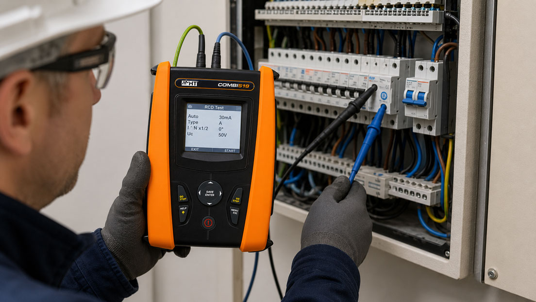
Residual current devices are not distinguished solely by their rated residual operating current. The RCD type is equally important. It defines the forms of alternating, pulsating direct, mixed-frequency or smooth direct residual current to which the protective device must respond reliably.
The RCD type therefore has a direct influence on the test procedure. If an RCD Type B is tested only with the test programme for Type A, the result may be correct for the selected pulsating residual-current waveform. However, this does not verify the all-current-sensitive function for smooth direct residual currents. Comparable issues arise with Type F, EV versions or a 6 mA DC residual-current detection function integrated into a wallbox.
Before every test, the type designation, rated residual operating current, time-delay characteristics and protection concept must therefore be identified clearly. Only then should the appropriate residual-current waveform, test current and test method be selected on the installation tester.
Table of Contents
- Why are there different RCD types?
- Comparison of RCD Types A, F, B and EV
- Testing an RCD Type A
- Testing an RCD Type F
- Testing an RCD Type B
- Testing an RCD Type EV and 6 mA DC detection
- Trip time, tripping current and ramp test
- Test procedure step by step
- Connected loads and leakage currents
- Variable-frequency drives, PV systems and charging infrastructure
- Typical errors and misinterpretations
- Practical example on a wallbox
- Selecting the correct installation tester
- Which measuring instruments / products are suitable?
- Conclusion
- Frequently asked questions
Why are there different RCD types?
An RCD compares the currents flowing in the live conductors of a circuit. If part of the current flows away through the protective conductor, an enclosure or another unintended path, a residual current is produced. If this exceeds the operating threshold of the protective device, the circuit is disconnected.
Conventional resistive loads predominantly produce sinusoidal residual currents at mains frequency. Modern electronic equipment, however, can generate significantly more complex residual-current waveforms. Rectifiers, variable-frequency drives, inverters, switched-mode power supplies and chargers may produce pulsating direct residual currents, mixed frequencies or smooth direct residual currents.
Not every RCD can detect all of these current waveforms. Under certain conditions, an unsuitable RCD may trip too late, at an excessively high current or not at all. Planning, selection and testing must therefore be appropriate for the connected equipment.
The test button on the RCD merely checks the internal tripping mechanism using a test current generated within the device. It does not replace measuring the trip time or testing with the residual-current waveforms specified for the relevant RCD type.
Comparison of RCD Types A, F, B and EV
| RCD type | Detected residual-current waveforms | Typical applications | Consequence for testing |
|---|---|---|---|
| Type A | Sinusoidal alternating and pulsating direct residual currents | General circuits and conventional single-phase electronic loads | Use the Type A test programme with the appropriate pulsating residual-current waveform |
| Type F | Type A residual-current waveforms plus defined mixed frequencies | Single-phase variable-frequency drives and variable-speed domestic or commercial equipment | The installation tester must explicitly support Type F testing |
| Type B | Alternating, pulsating and smooth direct residual currents, as well as frequency components within the device specification | Three-phase variable-frequency drives, inverters, machinery, PV systems and industrial installations | Use the all-current-sensitive test mode, including direct residual current |
| Type EV or A EV/F EV | Depending on the version, Type A or Type F behaviour plus detection of smooth direct residual currents within the EV protection function | AC charging points and wallboxes | Test the 30 mA RCD function and 6 mA DC detection separately or in accordance with the protection concept |
| RDC-DD | Monitoring of smooth direct residual currents, typically as part of charging equipment | Wallboxes and AC charging stations | A specific 6 mA DC test programme and, where applicable, an EVSE test adapter are required |
The designation “Type EV” is not always used consistently in practice. Some versions are based on Type A or Type F and additionally disconnect when a smooth direct residual current exceeds the intended EV threshold. A charging device may alternatively include a separate RDC-DD function.
Terms such as “EV-compatible” are therefore not sufficient on their own. The circuit diagram, protective-device markings and manufacturer documentation are decisive.
Testing an RCD Type A
An RCD Type A detects sinusoidal alternating residual currents and pulsating direct residual currents. It is found in many conventional final circuits and is frequently used with a rated residual operating current of 30 mA for additional protection.
The installation tester must be set to RCD Type A, the rated residual operating current stated on the protective device and the appropriate time-delay characteristic. Depending on the tester, the polarity or phase angle of the test current can also be selected, or both directions can be tested automatically.
Typical tests include:
- non-tripping test with a reduced test current,
- measurement of the trip time at a defined multiple of IΔn,
- ramp test to determine the actual tripping current,
- measurement of the touch voltage,
- testing with both polarities or phase angles.
The required combinations and applicable limits depend on the RCD, its intended use, the mains system and the relevant test specification.
Testing an RCD Type F
RCDs Type F are intended for applications in which mixed frequencies may occur in addition to the residual-current waveforms covered by Type A. Typical sources include single-phase variable-frequency drives and other variable-speed loads.
A Type F must not be equated with an all-current-sensitive Type B. In particular, it does not automatically replace a Type B in installations where relevant smooth direct residual currents may occur.
The installation tester must explicitly provide a Type F function for the test. A Type A test may check part of the tripping behaviour, but it does not fully reproduce the additional residual-current waveforms relevant to Type F.
Before testing, it should be checked whether the RCD is short-time delayed, selective or a standard version. An incorrect time-delay setting can cause a correctly operating RCD to be assessed falsely as defective.
Testing an RCD Type B
RCDs Type B are all-current sensitive. They are used where equipment may generate smooth direct residual currents or residual currents containing frequency components that cannot be detected reliably by a Type A or Type F.
Typical applications include:
- three-phase variable-frequency drives,
- machines with power-electronic drives,
- PV inverters where required by the protection concept,
- certain UPS and battery systems,
- test benches and industrial power converters,
- charging equipment without separate suitable DC residual-current detection.
The Type B mode of the installation tester must be selected for the test. This generates the test-current waveforms required for all-current-sensitive testing. A measurement in Type A mode is not sufficient, even if the RCD trips within the expected time.
Depending on the test instrument, rated residual operating current and selected residual-current waveform, Type B tests may take longer than conventional Type A tests. Some parameter combinations are not technically or normatively available for every test current. The permissible settings of the installation tester must therefore be observed.
The arrangement of multiple RCDs must also be checked. A downstream all-current-sensitive RCD and an upstream Type A must not be combined without assessing the complete protection and selectivity concept. Smooth direct residual currents may impair the function of unsuitable upstream RCDs.
Testing an RCD Type EV and 6 mA DC detection
Charging equipment for electric vehicles presents a particular issue: smooth direct residual currents from the vehicle or charger may flow towards the upstream installation. An upstream RCD Type A must not be impaired by an excessively high direct residual current.
Different protection concepts are therefore used in practice:
- all-current-sensitive RCD Type B,
- RCD Type A or F in combination with 6 mA DC residual-current detection,
- RCD in a special EV version,
- RDC-DD integrated into the wallbox plus a suitable upstream RCD.
These functions must not be confused during testing. A successful Type A test of the upstream 30 mA RCD does not automatically confirm that the 6 mA DC detection integrated into the wallbox is working.
Conversely, testing the 6 mA DC function does not replace the trip-time and tripping-current test of the upstream RCD. Both protection levels must be assessed according to the specific installation configuration.
An EVSE test adapter simulates the states of a connected electric vehicle and provides suitable measuring connections. Testing the residual current protective device additionally requires an installation tester with an appropriate RCD EV or RDC-DD test mode.
Trip time, tripping current and ramp test
A complete RCD test considers several characteristics. A single trip does not confirm that the RCD operates correctly in every relevant respect.
| Test | Purpose | Typical misinterpretation |
|---|---|---|
| Non-tripping test | Checks whether the RCD remains switched on at a current below its intended operating threshold | A trip is assessed prematurely as an RCD defect even though existing leakage currents are added to the test current |
| Trip time | Measures the time between applying the test current and disconnection | The wrong limit is used because standard, short-time delayed and selective RCDs are confused |
| Ramp test | Increases the test current in stages and determines the actual tripping current | The ramp value is assessed without considering existing installation leakage currents |
| Touch voltage | Assesses the voltage produced by the test current on the earthing or protective system | The mains system and earthing conditions are not considered during assessment |
| Testing both polarities | Detects differences caused by the starting point and polarity of the residual-current waveform | Only the more favourable measured value is documented |
Depending on the test task, a 30 mA RCD may additionally require testing at a higher multiple of the rated residual operating current. However, the test currents used and permissible disconnection times must not be applied universally to every RCD.
Test procedure step by step
RCD tests are generally performed under mains voltage and deliberately disconnect the circuit. They may only be carried out by appropriately qualified electrical personnel in accordance with company safety rules.
- Identify the installation and circuit: Determine the mains system, intended use, connected loads and possible consequences of disconnection.
- Read the RCD markings: Document the type, IΔn, rated current, number of poles, standard, short-time delayed or selective characteristics and manufacturer specifications.
- Check the protection concept: For variable-frequency drives, PV systems, machinery and EVSE, determine which residual-current waveforms may occur.
- Prepare the connected loads: Shut down sensitive or safety-related equipment in a controlled manner. Take existing leakage currents into account.
- Connect the installation tester: Connect the test lead, line conductor, neutral conductor and protective conductor in accordance with the instrument guidance.
- Set the RCD type: Select A, F, B, B+, EV or RDC-DD to match the installed protective device.
- Set the rated residual operating current: Select, for example, 30, 100 or 300 mA according to the marking.
- Select the time-delay characteristic: Set standard, short-time delayed or selective correctly.
- Test non-tripping and touch voltage: Where included in the test procedure.
- Measure the trip time: Apply the required test currents and polarities.
- Perform the ramp test: Determine the actual tripping current where required by the test task.
- Assess the results: Compare the measurement result with the RCD type, installation, manufacturer specifications and applicable test requirements.
- Document the results: Save the RCD type, IΔn, test mode, polarity, tripping current, trip time and test conditions.
Automatic test sequences can accelerate the procedure. However, they do not replace the correct identification of the RCD. An automatically performed measurement with the wrong RCD type selected remains technically invalid.
Connected loads and leakage currents
Connected equipment can significantly influence the result of an RCD test. Mains filters, variable-frequency drives, heaters, long cables and electronic devices produce leakage currents even during fault-free operation.
The installation tester generates an additional residual current during the test. However, the RCD responds to the sum of the test current and the existing leakage current. A ramp test may therefore indicate an apparently low tripping current even though the RCD itself is operating correctly.
Example: A leakage current of 8 mA is already flowing in a circuit. During the ramp test, the installation tester indicates tripping at an additional test current of 18 mA. In reality, approximately the sum of both currents is acting on the RCD. The result must therefore not be assessed without knowing the installation leakage current.
If the results are implausible, an additional measurement using a suitable leakage current clamp may be useful. Loads must not, however, be disconnected indiscriminately if this could impair operating or safety functions.
Variable-frequency drives, PV systems and charging infrastructure
Variable-frequency drives and machinery
Depending on their circuit topology, mains side and fault location, variable-frequency drives can generate different residual-current waveforms. A Type F may be suitable for certain single-phase applications. A Type B may be required for three-phase drives or where smooth direct residual currents are possible.
The selection must not be based solely on motor power. The decisive factors are the converter topology, manufacturer specifications, installed filters, mains system and complete protection concept.
Photovoltaic systems
Inverters in PV systems may also generate direct-current and mixed-frequency components. Whether an RCD is required and which type must be used depends on the inverter, galvanic isolation, installation concept and manufacturer specifications.
Automatically replacing an existing Type A with a Type B is no more technically correct than assuming that every modern inverter automatically requires a Type B.
Wallboxes and AC charging points
At charging points, the upstream RCD, integrated DC detection and EVSE control system must be considered together. In addition to RCD testing, relevant checks include the protective conductor, insulation resistance, mains and loop impedance, and the states of the Control Pilot and Proximity Pilot.
An installation tester with an EVSE function and suitable charging-point adapter is particularly useful for this combined test procedure.
Typical errors and misinterpretations
Type B is tested in Type A mode
The RCD may trip with the residual-current waveform used. However, the detection of smooth direct residual currents that is decisive for Type B has not been verified.
Type F is treated as Type A
A Type A test does not automatically cover the additional response to mixed frequencies. The test instrument must explicitly support Type F.
EVSE testing and RCD testing are treated as the same procedure
Simulating a vehicle state does not automatically confirm the correct tripping of the RCD or the DC residual-current monitoring. Both functions require suitable tests.
The test button is regarded as complete verification
The button checks an internal function, but it does not provide a measured trip time, ramp value or verification of all residual-current waveforms relevant to the RCD type.
A selective RCD is set as a standard RCD
The intentionally delayed trip can therefore be assessed incorrectly as exceeding the permitted limit.
Existing leakage currents are ignored
This can make ramp values appear too low or cause an RCD to trip during a non-tripping test.
Only one test result is documented
Without stating the RCD type, IΔn, test current, polarity and time-delay characteristic, the measured value can hardly be assessed correctly at a later date.
Practical example: RCD testing on a wallbox
An AC wallbox is protected by an upstream RCD Type A with IΔn = 30 mA. According to the manufacturer, the wallbox additionally has integrated DC residual-current detection with a threshold of 6 mA.
During the first test, only Type A is selected on the installation tester. The upstream RCD trips at a plausible value during the ramp test, and the measured trip time is within the applicable requirement.
However, this result confirms only the tested function of the upstream Type A RCD. The integrated direct residual-current detection of the wallbox has not yet been checked.
In the second step, an EVSE test adapter is connected. It simulates a connected vehicle and places the charging equipment in the required operating state. A smooth direct residual current is then generated using the EV or RDC-DD test programme.
The wallbox must respond at the intended residual-current threshold and safely interrupt the charging process. The protective conductor, mains and loop impedance, insulation resistance and EVSE control states are also tested.
The example shows that the Type A test and the test of the 6 mA DC detection function are two separate test tasks. Only together do they represent the specific protection concept of the charging equipment.
Selecting the correct installation tester
An installation tester for modern installations should be capable of testing more than conventional Type A RCDs. Before selecting a tester, it is necessary to determine which protective devices and applications are actually encountered.
Important selection criteria include:
- supported RCD types A, AC, F, B, B+, EV and RDC-DD,
- available rated residual operating currents,
- testing of standard, delayed and selective RCDs,
- measurement of the trip time,
- ramp test for determining the tripping current,
- automatic testing of both polarities,
- measurement of the touch voltage,
- loop measurement without tripping the RCD,
- automatic sequences for recurring installation tests,
- memory and documentation functions,
- EVSE test procedure and compatible charging-point adapter,
- suitable measurement category for the intended application.
The instrument must not only be technically capable of generating the test waveform for the RCD type in use. Its user interface should also indicate clearly which residual-current waveform, polarity, current level and time function are currently selected.
Which measuring instruments / products are suitable?
COMBI519 installation tester
The COMBI519 installation tester is suitable for comprehensive installation testing and supports tests on different RCD types, including Types A, F and B/B+, as well as EV or RDC-DD test functions depending on the instrument version and selected test parameters.
Trip time and tripping current can be tested manually or in automated procedures. The automatic sequence combines earth or loop measurement without tripping the RCD, RCD testing and insulation measurement. Memory and a USB interface are also available for documentation.
The COMBI519 is particularly suitable where conventional installation testing must be combined with demanding RCD tests on machinery, variable-frequency drives, commercial installations and industrial systems.
COMBI521 installation tester
The COMBI521 installation tester provides the RCD and installation tests of the COMBI519 and adds advanced analysis, communication and EVSE functions.
In combination with the optional EV-TEST100, charging equipment can be checked using a menu-guided or automated EVSE test procedure. The adapter simulates vehicle states and provides the connections required for the electrical safety measurements.
The COMBI521 is therefore particularly suitable for users who need to test and document not only conventional RCD Types A, F and B, but also wallboxes, AC charging stations, EV protective devices and integrated DC residual-current detection functions.
Conclusion: The RCD type determines the required residual-current waveform
A technically correct RCD test does not begin by pressing the start button on the installation tester, but by clearly identifying the protective device. Types A, F, B and EV respond to different residual-current waveforms and must therefore not be tested using the same standard programme.
Type A covers sinusoidal alternating and pulsating direct residual currents. Type F additionally takes defined mixed frequencies into account. Type B must also detect smooth direct residual currents and additional frequency components. Charging equipment frequently includes separate 6 mA DC detection, which must be checked independently of the 30 mA RCD test.
Trip time, tripping current, polarity, time-delay characteristics and existing leakage currents must be assessed together. A successful trip alone is not complete proof of correct operation.
Installation testers such as the COMBI519 and COMBI521 support the necessary RCD test modes. For charging infrastructure, the COMBI521 in combination with an EVSE adapter provides a structured test procedure combining conventional installation measurements with EV-specific functions.
Frequently asked questions about testing RCD Types A, F, B and EV
Can an RCD Type B be tested using the Type A setting?
This only checks the response to the generated Type A residual-current waveform. The all-current-sensitive function for smooth direct residual currents is not verified. The Type B mode is required for a complete test.
Is Type F the same as Type B?
No. Type F extends the detection characteristics of Type A to include certain mixed frequencies. A Type B is all-current sensitive and additionally detects smooth direct residual currents within its specification.
What does RCD Type EV mean?
The designation is used for protective devices intended for charging equipment that additionally include defined direct residual-current detection. Depending on the product, the version may be based on Type A or Type F. The exact function must be determined from the device markings and manufacturer documentation.
Must an RCD Type B always be installed for a wallbox?
Not necessarily. Depending on the charging equipment, a suitable RCD Type A or F may be used together with integrated 6 mA DC residual-current detection. The installation concept, manufacturer specifications and applicable installation requirements are decisive.
What does the ramp test show?
The installation tester increases the residual current in stages until the RCD trips. This determines the actual tripping current. Existing leakage currents in the installation can influence the result.
Is the test button on the RCD sufficient?
No. The test button checks the internal mechanism, but it does not provide measured values for the trip time, tripping current or touch voltage and does not automatically test all residual-current waveforms relevant to the RCD type.
Why does the RCD trip at a low test current?
One possible cause is existing leakage current from connected loads. This is added to the test current generated by the installation tester. A defective load, wiring fault or an RCD that genuinely trips too early may also be the cause.
Which information does ICS Schneider require for product selection?
The required information includes the installed RCD types, rated residual operating currents, standard or selective characteristics, mains system, applications such as variable-frequency drives, PV or EVSE, required installation measurements, documentation requirements and details of the required EVSE adapters and interfaces.