


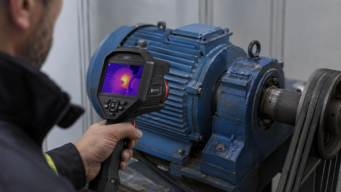
Electric motors, bearings, couplings and belt drives generate heat during operation. A certain rise in temperature is normal because electrical losses, friction and mechanical load convert part of the energy used into heat. It becomes noticeable when individual components are significantly warmer than comparable components, the temperature rises within a short period or the thermal behaviour changes compared with previous measurements.
A thermal imaging camera makes such temperature distributions visible without contact. Thermography is therefore particularly suitable for the preventive maintenance of motors, pumps, fans, gearboxes, conveyor systems and other rotating machinery. It enables rapid inspection during operation without having to measure every point individually using a contact probe.
However, a thermal image alone does not provide a definitive fault diagnosis. An elevated bearing temperature can, for example, be caused by insufficient lubrication, over-lubrication, misalignment, increased load or an incipient bearing defect. Reproducible measuring conditions, reference values and joint evaluation with operating data, noise, vibration and electrical measurements are therefore essential.
Table of Contents
- What does thermography show on motors and bearings?
- Which areas should be inspected?
- Typical thermal anomalies and possible causes
- Considering load conditions and operating time
- Correctly assessing overheated bearings
- Assessing the motor housing, winding and cooling
- Inspecting belts, couplings and shafts
- Correctly setting emissivity and reflected temperature
- Comparative measurements and trend analysis
- Carrying out thermal inspections safely
- Practical example on a pump motor
- Selecting a thermal imaging camera for machine inspection
- Which measuring instruments / products are suitable?
- Conclusion
- Frequently asked questions
What does thermography show on motors and bearings?
A thermal imaging camera detects the infrared radiation emitted by a surface and uses it to display a temperature distribution. Warm and cold areas are made visible within a selected colour palette. Temperature differences can therefore often be detected more quickly than with individual point measurements.
On rotating machinery, thermal anomalies can indicate increased friction, electrical overload, insufficient cooling or uneven mechanical loading, among other things. Thermography is particularly helpful when several identical motors, bearing positions or drive units can be inspected under comparable conditions.
In principle, the surface temperature is measured. The camera cannot see directly inside a closed bearing or into the winding of a motor. An elevated internal temperature must first be transferred to the visible surface through the housing, bearing cover or shaft. There may therefore be a time delay between the development of a fault and visible heating.
An inconspicuous surface also does not reliably rule out an incipient defect. Small faults or faults located deep within a component may not yet be thermally detectable. Thermography is therefore an important diagnostic tool, but on critical machinery it should be combined with other testing methods.
Which areas should be inspected?
A complete thermal inspection does not only consider the hottest point on the motor. For a meaningful assessment, several defined measuring areas should be recorded and documented.
| Inspection area | What should be checked? | Possible anomaly |
|---|---|---|
| Drive-end bearing | Temperature at the bearing cover and transition to the motor housing | Friction, misalignment, increased belt or coupling forces |
| Non-drive-end bearing | Comparison with the opposite bearing position | Bearing damage, lubrication problem or restricted cooling |
| Motor housing | Temperature distribution over its length and circumference | Overload, uneven heating or internal power losses |
| Cooling fins and fan end | Unobstructed airflow and even heat dissipation | Contamination, blocked fan or insufficient airflow |
| Terminal box | Local hotspots at connections and cable entries | Loose connection, contact resistance or unbalanced loading |
| Coupling and shaft | Symmetry and temperature differences between the coupling halves | Misalignment, friction or mechanical stress |
| Belt drive | Belt flanks, pulleys and bearing areas | Slippage, incorrect tension, alignment error or overload |
| Connected machine | Also inspect the pump, fan, gearbox or compressor | Process-related overload or mechanical resistance |
For recurring inspections, the measuring points should be recorded from the same perspective and distance wherever possible. A clear designation, such as “Motor 3 – drive-end bearing”, considerably simplifies subsequent comparisons.
Typical thermal anomalies and possible causes
The thermal pattern often provides an initial indication of where the cause of heating may lie. However, the final diagnosis must always be application-specific.
One bearing is significantly warmer than the other
A temperature difference between the drive end and non-drive end may result from different mechanical loads. In a belt drive, for example, the drive-end bearing absorbs additional radial forces. Greater heating may therefore be explained by the design.
If the temperature rises significantly compared with previous measurements or an identical machine, the lubrication condition, bearing clearance, alignment, shaft load and vibration should be checked.
The entire motor housing is unusually warm
Severe, uniform heating can indicate a high electrical or mechanical load. Possible causes include an overloaded process, excessive switching frequency, unfavourable environmental conditions or restricted cooling.
The motor current, supply voltage, load condition, ambient temperature and permissible operating conditions of the motor should be considered during the assessment.
A local area of the housing is particularly hot
A localised hotspot can be caused by internal heating, uneven airflow, contamination or a nearby heat source. On bare or shiny housing components, it must also be checked whether only a hot surrounding object is being reflected.
The fan end remains hot
If heat is not dissipated sufficiently at the fan end, contaminated ventilation grilles, blocked cooling fins, a damaged fan or an incorrect direction of rotation may be present. Insufficient clearance from walls or machine guards can also impair the cooling airflow.
Belts or pulleys show elevated temperatures
Severe heating can indicate slippage, incorrect pre-tension, worn belts or misaligned pulleys. Differences between individual belts in a multiple-belt drive are also often visible.
Considering load conditions and operating time
Temperatures on motors and bearings can only be assessed meaningfully when the operating condition is known. A measurement taken directly after start-up cannot be compared with an image recorded after several hours at full load.
At least the following operating data should be documented before recording the image:
- operating time since start-up,
- current machine load or process output,
- speed and operating mode,
- motor current, if available,
- ambient and room temperature,
- frequency of the variable-frequency drive, where applicable,
- special process conditions during the measurement.
A load condition that is as stable as possible is ideal for recurring inspections. If a motor is recorded once at 40 percent and later at 90 percent of its typical load, a temperature difference may be caused solely by the change in load.
The ambient temperature must also be considered. A bearing at 60 °C in an ambient temperature of 40 °C must be assessed differently from the same bearing at 60 °C in an ambient temperature of 15 °C. For trend analyses, the temperature difference relative to the surroundings or a suitable reference point can therefore also be documented.
Correctly assessing overheated bearings
Bearings generate heat through rolling and sliding friction. The actual operating temperature depends, among other things, on the bearing design, speed, load, lubricant, seal, installation and heat dissipation. A universal temperature limit for all bearing applications is therefore not appropriate.
An elevated bearing temperature may have various causes:
- insufficient lubricant,
- excessive grease after relubrication,
- unsuitable or aged lubricant,
- contamination or moisture in the bearing,
- misalignment between the motor and driven machine,
- excessive belt tension or coupling forces,
- incorrect bearing clearance or mechanical stress,
- damaged raceways or rolling elements,
- increased process load.
After relubrication, the temperature may rise temporarily, particularly if too much grease has been added and the bearing must displace the excess lubricant. A short-term temperature increase should therefore not be assessed in isolation. If the temperature remains elevated or continues to rise, a more detailed inspection is required.
The thermal imaging camera should be aimed at the bearing cover or at a readily reproducible area in the immediate vicinity of the bearing position. The measured housing temperature does not exactly correspond to the temperature of the raceway or rolling elements.
If bearing damage is suspected, supplementary vibration analysis is particularly helpful. It can often detect mechanical anomalies before significant heating becomes visible on the surface.
Assessing the motor housing, winding and cooling
The heat distribution on the motor housing is determined by internal power losses and external cooling. A loaded motor does not heat up at only one point. A temperature profile typically develops across the housing, bearing areas and fan end.
The winding temperature cannot be measured directly from outside using a thermal imaging camera. The camera only detects the temperature of the visible housing surface. Depending on the motor design, built-in temperature sensors, resistance measurements or manufacturer-specific monitoring methods are required to determine the winding temperature accurately.
Nevertheless, surface thermography provides important indications. An overall increase in housing temperature can indicate overload or impaired cooling, for example. A temperature comparison is particularly meaningful for identical motors operating under similar loads.
The following points should be considered when checking the cooling system:
- unobstructed and clean ventilation openings,
- clean cooling fins,
- intact fan and correct direction of rotation,
- sufficient clearance from walls and guards,
- no unusually hot cooling air being drawn in,
- no deposits of dust, oil or fibres.
On separately ventilated motors, it should also be checked whether the external fan is actually running. Particularly at low speeds on a variable-speed motor, self-cooling may be reduced while the mechanical load remains high.
Inspecting belts, couplings and shafts
Thermography should not stop at the motor housing. The cause of an elevated motor temperature is often found in the connected mechanical system.
On couplings, misalignment, mechanical stress or damaged flexible elements can result in additional friction and bearing load. Noticeable temperature differences between the two coupling sides should be assessed together with alignment and vibration measurements.
Slippage can generate heat in belt drives. A single warm belt within a multiple-belt set may indicate uneven load distribution or a different level of wear. Pulleys or bearing positions with differing temperatures can also indicate alignment and tensioning problems.
Rotating shafts are more difficult to measure thermographically. Reflections, movement and the small visible surface can affect the measured value. The temperature at a stationary bearing housing or adjacent component is often more meaningful and easier to reproduce.
Correctly setting emissivity and reflected temperature
The reliability of a thermographic temperature measurement depends substantially on the surface of the measured object. In simplified terms, emissivity describes how effectively a surface emits infrared radiation compared with an ideal emitter.
Painted, oxidised or contaminated motor housings can often be measured more reliably than bare, polished metal surfaces. Shiny metals have low emissivity and reflect a large proportion of the thermal radiation from their surroundings. An apparent hotspot may therefore actually be the reflection of a radiator, warm pipe, person or even the operator.
For comparative measurements, areas with the same surface condition should be used wherever possible. If an accurate temperature measurement is required, a reference area with a known emissivity can be established at a suitable and permissible location, for example using appropriate emissivity tape or a matt coating.
Moving parts, hot surfaces or safety-related components must not be modified in an impermissible manner. The material used for the reference area must be suitable for the temperature, environment and machine.
In addition to emissivity, the reflected ambient temperature, measuring angle, distance, atmospheric influences and focus can affect the result. When merely searching for relative temperature differences, these factors are sometimes less critical than for an accurate absolute temperature measurement. Nevertheless, they should be kept as constant as possible.
Comparative measurements and trend analysis
The greatest benefit of thermography often comes not from a single temperature value, but from comparing several images.
Comparison of identical components
Several identical motors within a system can be compared under similar operating conditions. If one bearing is significantly warmer than the corresponding bearing positions on the other motors, there is a clear reason for further inspection.
Comparison between the drive end and non-drive end
The two bearing positions on a motor may have different temperatures. The key question is whether the difference can be explained by the design and loading or whether the relationship changes over time.
Trend analysis across several inspections
Gradual changes can be identified by recording thermograms regularly. The measuring point, camera position, focus, emissivity, load condition and recording parameters should be kept as consistent as possible.
Appropriate documentation includes at least:
- clear identification of the machine and measuring point,
- date and time,
- thermogram and, where applicable, visible-light image,
- temperature values for defined measuring areas,
- ambient temperature,
- load and operating condition,
- identified deviation,
- recommended or completed action.
Internal warning and intervention limits can be defined for assessment purposes. These should be derived from manufacturer specifications, experience, historical measurements and the criticality of the machine. A universal limit for all motors and bearings is not technically appropriate.
Carrying out thermal inspections safely
A thermal imaging camera enables contactless measurements, but it does not eliminate the hazards of an operating machine. Rotating shafts, couplings, belts and fans must not be touched. Required safety distances and company safety rules must be observed.
Protective guards should not be removed solely to obtain a thermographic image. If inspection with an open guard is technically necessary, it may only be carried out as part of an appropriate risk assessment and a defined safe procedure.
The following procedure is recommended for reproducible recordings:
- Clearly document the machine, measuring point and operating condition.
- Switch on the camera, allow it to acclimatise and set the appropriate measurement parameters.
- Focus the measuring surface sharply.
- Take an overview image of the motor and driven machine.
- Take defined detailed images of both bearing positions, the housing, cooling system and drive.
- Check for hotspots and temperature differences.
- Inspect conspicuous areas from a slightly different angle to identify reflections.
- Assess the results against previous images or comparison machines.
- Arrange supplementary electrical or mechanical tests if anomalies are found.
Practical example: Heating on a pump motor
In a production plant, a pump motor is regularly inspected using thermography. The motor has been running for two hours under a largely constant load. The ambient temperature is 24 °C.
The following surface temperatures are found during the inspection:
- Motor housing: 54 °C
- Non-drive-end bearing housing: 57 °C
- Drive-end bearing housing: 73 °C
- Pump bearing on the coupling side: 69 °C
During the previous measurement under a comparable load, the drive-end motor bearing was at 59 °C. The temperature increase of 14 K and the likewise elevated temperature at the pump bearing indicate that the motor bearing should not be considered in isolation.
A subsequent vibration measurement shows increased vibration values in the axial direction. During the mechanical inspection, a misalignment between the motor and pump is identified. After aligning the coupling and restarting the machine, the temperature of the drive-end bearing housing stabilises at 60 °C.
The example shows that thermography can make an anomaly visible at an early stage. However, the actual cause was only identified conclusively by combining vibration measurement with mechanical inspection.
Selecting a thermal imaging camera for machine inspection
For regular inspections of motors and bearings, the maximum temperature measuring range is not the only decisive factor. The camera must be able to detect small temperature differences and sufficiently small components from the intended distance.
Important selection criteria include:
- IR detector resolution,
- thermal sensitivity or NETD,
- suitable field of view and appropriate lenses,
- manual or automatic focusing,
- smallest reliably measurable area at the working distance,
- temperature measuring range,
- radiometric storage of image data,
- measurement functions for points, lines and areas,
- possibility of subsequent analysis,
- image, report and measuring-point management,
- robustness, degree of protection and battery life,
- video, streaming or interface functions, where required.
A higher IR resolution makes it easier to detect small bearing positions and fine temperature patterns. Thermal sensitivity describes how small a temperature difference the camera can display. Radiometric images are important for trend analyses and professional documentation because the temperature information for individual image areas can be evaluated later.
The lens must suit the measuring distance and size of the object being inspected. A wide field of view is suitable for overview images in confined machine rooms. For small bearing positions at greater distances, a higher geometrical resolution or suitable telephoto lens may be required.
Which measuring instruments / products are suitable?
Advanced thermal imaging cameras
The Advanced Thermal Imaging Cameras category includes cameras for more demanding maintenance, electrical, building and industrial inspections. They are suitable for users who require professional analysis, focusing and reporting functions in addition to good image quality.
For recurring motor and bearing inspections, sufficient IR resolution, good thermal sensitivity and reproducible focusing are particularly important. Models with interchangeable lenses may be useful when both large machine overviews and small measuring points at greater distances must be recorded.
Premium thermal imaging cameras
The Premium Thermal Imaging Cameras category is intended for professional thermography applications with higher requirements for image resolution, detail recognition, measurement functions and documentation.
These cameras are particularly suitable for extensive maintenance programmes, critical machines, large equipment populations and applications in which small thermal anomalies must be located reliably from greater distances.
HIKMICRO G31, G41 and G61
The HIKMICRO G31, HIKMICRO G41 and HIKMICRO G61 are handheld thermal imaging cameras for professional industrial and preventive inspections.
The most suitable version depends particularly on the size of the bearing positions to be inspected, the measuring distance, the required thermal detail recognition and the desired scope of documentation.
testo 883
The testo 883 versions offered in the advanced category are suitable for professional thermographic inspections with manual focusing, analysable thermal images and software-supported reporting.
The choice between different lens versions should be based on the available distance, the size of the motor and the smallest relevant measuring point.
Conclusion: Thermography makes heat-related problems visible before the machine fails
A thermal imaging camera can quickly and non-invasively identify unusual temperature distributions on motors, bearings, couplings, belts and cooling systems. This allows friction, overload, misalignment and cooling problems to be detected at an early stage.
However, a single temperature value is rarely sufficient for a reliable assessment. The load condition, operating time, ambient temperature, surface and measuring angle must be considered. Comparisons with identical machines and trend images recorded under reproducible conditions are particularly meaningful.
Thermography shows where an anomaly is present. The precise cause may then need to be determined using current measurement, vibration analysis, lubricant inspection, alignment or mechanical testing.
For professional maintenance tasks, the thermal imaging camera should suit the size of the measuring points, the working distance and the required scope of documentation. Sufficient IR resolution, good thermal sensitivity and precise focusing are often more important for motor and bearing inspections than a particularly wide maximum temperature measuring range.
Frequently asked questions about thermography on motors and bearings
What temperature is still normal for a motor bearing?
There is no universal limit for all motor bearings. The permissible temperature depends on the bearing design, lubricant, speed, load, seal, environment and manufacturer specifications, among other factors. Changes compared with previous measurements and comparable bearing positions are particularly important.
Can a thermal imaging camera reliably identify bearing damage?
It can reveal unusual heating that indicates increased friction or loading. However, an incipient bearing defect may already cause vibrations before the surface temperature changes significantly. Supplementary vibration analysis is often required for a reliable diagnosis.
Can the motor winding temperature be measured directly?
No. On a closed motor, the thermal imaging camera only measures the visible housing surface. Built-in temperature sensors or other motor-specific methods are required for direct monitoring of the winding.
Why does a bare metal surface appear unusually hot?
Bare metal often has low emissivity and reflects thermal radiation from the surroundings. The displayed hotspot may therefore be a reflection. Recording the area from a different angle and using a suitable reference area can assist with the assessment.
Should a motor be inspected immediately after start-up?
An image recorded during the warm-up phase can be useful for certain investigations. For recurring condition comparisons, however, the motor should be thermally stabilised under a defined and comparable load condition wherever possible.
How often should motors be inspected thermographically?
The inspection interval depends on criticality, operating time, load, consequences of failure and previous anomalies. Critical machines may be inspected more frequently than redundant or rarely operated drives. The intervals should be defined in the maintenance programme and adjusted based on the measurement results.
Is an inexpensive thermal imaging camera sufficient for the inspection?
This depends on the measuring distance, size of the bearing positions and required level of information. A simpler camera may be sufficient for large, easily accessible motor housings. Small bearing positions, long distances and professional trend analyses often require a higher IR resolution, better thermal sensitivity and more comprehensive analysis functions.
Which information does ICS Schneider require for product selection?
The required information includes the size of the motors and bearing positions, typical measuring distance, smallest area to be detected, expected temperature range, environmental conditions, required documentation, necessary analysis functions and whether interchangeable lenses, video recording, streaming or special interfaces are required.