


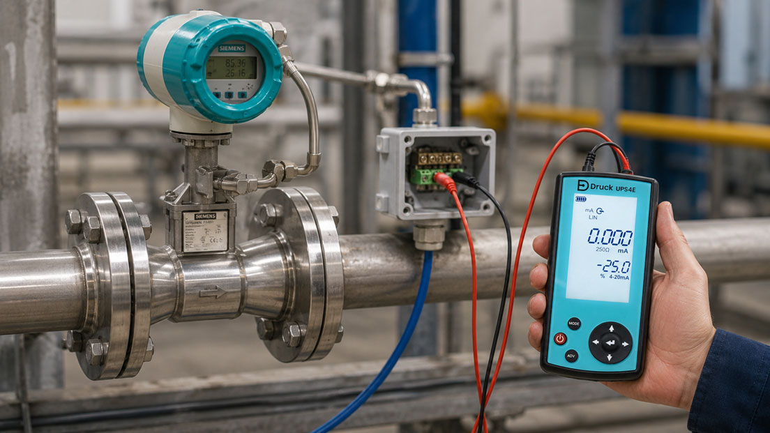
A Vortex flowmeter often provides several items of information simultaneously. Depending on the version, these may include the current flow rate, a 4–20 mA signal, HART variables, a quantity-proportional pulse output and internal totalisers. For steam and gas applications, additional values such as temperature, pressure, density, standard volume, mass flow or energy may also be calculated.
In practice, many discrepancies are not caused by the Vortex measuring principle itself, but by an incorrect assignment of the output variables. For example, the display may show a mass flow in kg/h while the analogue output is still configured for actual volumetric flow in m³/h. Alternatively, the pulse output may be evaluated using a different unit and pulse value than the one stored in the PLC.
This becomes particularly critical for energy billing, consumption balances and cost-centre allocation. The instantaneous flow rate may appear plausible on the display, while the PLC totaliser records a significantly excessive or insufficient quantity over several weeks because the pulse value has been entered incorrectly.
This article explains how the 4–20 mA, HART, pulse output and totalisers of a Vortex flowmeter are correctly assigned, scaled and tested. The SITRANS FX300 Vortex flowmeter is used as a specific example. Further instruments can be found in the Coriolis and Vortex flowmeters category.
Contents
- Which measured variables can a Vortex instrument output?
- Distinguishing between actual volume, standard volume and mass
- Comparing 4–20 mA, pulse and HART
- Correctly scaling the 4–20 mA output
- Why square-root extraction is not required in the PLC
- Evaluating fault currents and invalid measured values
- Correctly using a quantity-proportional pulse output
- Selecting a suitable pulse value
- Comparing the internal and external totalisers
- Correctly counting the pulse signal in the PLC
- Using additional measured values via HART
- Systematically comparing the display and control system
- Performing a 4–20 mA loop check
- Testing the pulse output and counter input
- Practical example: Steam measurement with incorrect PLC scaling
- Recommended commissioning procedure
- Which products are suitable?
- Conclusion
- Frequently asked questions
Which measured variables can a Vortex instrument output?
The Vortex measuring principle initially detects the frequency of the vortices that form behind a bluff body in the pipe. Within the usable measuring range, this frequency is proportional to the flow velocity. The transmitter calculates the volumetric flow under the current operating conditions from the flow velocity and pipe cross-section.
Depending on the instrument version and configuration, additional variables can be derived from this:
- actual volumetric flow in m³/h, l/min or another volume unit,
- standard volumetric flow in Nm³/h or m³n/h,
- mass flow in kg/h or t/h,
- medium temperature,
- process pressure with integrated or external pressure measurement,
- calculated density,
- thermal power or energy for suitable applications,
- totalised actual volume, standard volume, mass or energy.
These values must not be interchanged without clear identification. A numerical value of 500 may mean 500 m³/h actual volume, 500 Nm³/h standard volume or 500 kg/h mass. Without the unit and reference conditions, the value is not completely defined.
Distinguishing between actual volume, standard volume and mass
Actual volumetric flow
The actual volumetric flow describes the volume flowing through the pipe under the actual pressure and temperature conditions. The unit may be m³/h, for example.
This value is often sufficient for liquids with only minor changes in density. For gases and steam, however, the volume can change considerably with pressure and temperature.
Standard volumetric flow
The standard volumetric flow converts the gas volume to defined reference conditions. These reference conditions must be configured identically in the measuring instrument and the control system. Different reference temperatures alone can already cause noticeable discrepancies.
The specification “Nm³/h” is therefore not complete on its own. The reference temperature, reference pressure and, where applicable, humidity condition to which the value refers must also be documented.
Mass flow
Mass flow indicates the actual mass transported per unit of time. For steam, it is frequently expressed in kg/h or t/h. In a Vortex instrument, it is not measured directly, but calculated from the volumetric flow and the determined or configured density.
For this calculation to be correct, the medium, pressure, temperature and density calculation must match the application. An incorrect medium selection can therefore produce an electrically correct but process-technically incorrect output signal.
| Measured variable | Typical unit | Particularly important for |
|---|---|---|
| Actual volumetric flow | m³/h, l/min | Liquids and processes with largely constant density |
| Standard volumetric flow | Nm³/h, m³n/h | Gas consumption, compressed air and technical gases |
| Mass flow | kg/h, t/h | Steam, material balances and mass-based billing |
| Energy or thermal power | kW, MJ/h, kJ/h | Steam and heating-network monitoring |
| Total quantity | m³, Nm³, kg, t, MJ | Consumption, billing and cost centres |
Comparing 4–20 mA, pulse and HART
| Signal | Typical content | Strength | Typical source of error |
|---|---|---|---|
| 4–20 mA | Instantaneous flow rate or thermal power | Robust continuous transmission | Incorrect lower or upper range value in the PLC |
| Quantity pulse | Defined quantity per pulse | Direct totalisation without time-based integration | Incorrect pulse value or lost pulses |
| Internal totaliser | Total actual volume, standard volume, mass or energy | Calculated directly in the measuring instrument | Incorrect unit or uncontrolled reset |
| HART | Primary value, additional measured values, parameters and status | Several items of information over the same current loop | Incorrect variable assignment or missing communication |
A combination is useful for many applications. The instantaneous flow rate is transmitted via 4–20 mA for control and indication. The pulse output sends the consumed quantity to a counter input. Additional values and instrument settings can be checked via HART.
Correctly scaling the 4–20 mA output
The analogue output assigns 4 mA to a lower process value and 20 mA to an upper process value. The transmission between these points is linear.
The general calculation is:
Measured value = lower range value + (current − 4 mA) / 16 mA × measuring span
The measuring span is calculated as follows:
Measuring span = upper range value − lower range value
Example: 0 to 10 t/h
| Current signal | Percentage of span | Flow rate |
|---|---|---|
| 4 mA | 0% | 0 t/h |
| 8 mA | 25% | 2.5 t/h |
| 12 mA | 50% | 5 t/h |
| 16 mA | 75% | 7.5 t/h |
| 20 mA | 100% | 10 t/h |
At 14.4 mA, the result is:
(14.4 mA − 4 mA) / 16 mA = 0.65
0.65 × 10 t/h = 6.5 t/h
At least the following parameters in the PLC must therefore match the Vortex instrument:
- output variable,
- lower range value,
- upper range value,
- unit,
- reference conditions,
- damping,
- fault-current configuration.
A common source of error occurs after the measuring instrument has been reconfigured. If the upper range value in the FX300 is changed from 10 to 15 t/h, for example, the PLC scaling must also be adjusted. Otherwise, the display and the control system will agree only at the zero point.
Why square-root extraction is not required in the PLC
The 4–20 mA output of a Vortex flowmeter is normally already linear in relation to the configured flow value. Additional square-root extraction in the PLC is therefore not required.
Square-root extraction is typically required for differential-pressure flow measurement because the differential pressure is proportional to the square of the flow rate. If this function is mistakenly applied to an already linearised Vortex signal, the PLC displays a severely distorted flow value.
At 25% of the actual measuring range, a linearly scaled Vortex output supplies 8 mA. If the PLC then applies a square-root function, this is mathematically converted into 50% of the measuring range. The indicated flow rate would therefore be twice the actual value.
Evaluating fault currents and invalid measured values
A 4–20 mA signal must not be processed only as a numerical value. Values outside the normal measuring range must also be evaluated. Depending on its configuration, the SITRANS FX300 can output an upper or lower fault current.
Typical states include:
- 4 mA: valid lower range value,
- 20 mA: valid upper range value,
- slightly above 20 mA: possible overrange condition within the permissible output range,
- approximately 22 mA: configured upper fault signal,
- approximately 3.55 mA: configured lower fault signal.
The PLC should not convert such values into an apparently valid flow rate. Separate status information is preferable:
- measured value valid,
- below measuring range,
- above measuring range,
- instrument fault,
- open circuit or missing power supply.
The thresholds used must match the actual transmitter configuration. If an upper fault current is configured in the FX300, the PLC must not monitor only for a lower fault current.
Correctly using a quantity-proportional pulse output
A quantity-proportional pulse output does not transmit a continuous analogue variable. Each pulse represents a defined quantity. This quantity may relate to actual volume, standard volume, mass or energy, for example.
The total quantity is calculated as follows:
Total quantity = number of pulses × quantity per pulse
Example:
- Pulse value: 10 kg per pulse
- Number of pulses counted: 12,500
Total quantity = 12,500 × 10 kg = 125,000 kg = 125 t
On the SITRANS FX300, the pulse output is designed as a passive, galvanically isolated output. It requires a suitable external power supply or input circuit. If the current and pulse outputs are used simultaneously, the two signal circuits must be supplied separately in accordance with the connection instructions.
The maximum pulse rate is particularly important. On the FX300, it is 0.5 pulses per second or 1,800 pulses per hour. The pulse value must therefore be selected so that this limit is not exceeded at the maximum flow rate.
Selecting a suitable pulse value
If the pulse value is too fine, more pulses are generated at high flow rates than the output can supply. If the pulse value is too coarse, however, long intervals occur between pulses at low flow rates.
The following relationship can be used to determine the minimum quantity per pulse:
Quantity per pulse ≥ maximum flow rate / maximum number of pulses per hour
Example: Maximum 9,000 kg/h
With a maximum of 1,800 pulses per hour, the result is:
9,000 kg/h / 1,800 pulses/h = 5 kg per pulse
A setting of 1 kg per pulse would be too fine for this maximum flow rate. It would require 9,000 pulses per hour or 2.5 pulses per second. The output, however, can supply only 0.5 pulses per second.
Suitable settings would include:
- 5 kg per pulse: exactly 0.5 Hz at maximum flow,
- 10 kg per pulse: 0.25 Hz at maximum flow,
- 100 kg per pulse: only 0.025 Hz, but with low temporal resolution.
The selection is a compromise between the maximum output frequency and the required quantity resolution. A coarser pulse value is often uncritical for energy or consumption balances. For small batches, however, it may be unsuitable.
Comparing the internal and external totalisers
The internal totaliser of the Vortex instrument is calculated from the internally determined flow rate. The PLC can additionally maintain its own totaliser using the pulse output. With the same unit and pulse value, both values should largely agree over the long term.
Small differences may be caused by:
- the time at which the values are read,
- pulses that have not yet been completely transmitted,
- display rounding,
- different start-up or shutdown times,
- totaliser reset,
- failure of the PLC or counter module,
- changes to the pulse value,
- PLC totaliser values that have not been retained.
Large or continuously increasing discrepancies, however, frequently indicate incorrect scaling or lost pulses.
| Indication in the FX300 | PLC totaliser | Possible cause |
|---|---|---|
| Increases while the PLC remains unchanged | No pulses | Wiring, power supply, input or pulse output disabled |
| PLC counts twice the quantity | Factor of 2 too high | Incorrect pulse value or both signal edges being counted |
| PLC counts only intermittently | Pulses are missing | Input filter, acquisition time too short or unsuitable PLC cycle |
| Values initially agree and later drift apart | Increasing discrepancy | Lost pulses, counter overflow or non-retained totaliser value |
| Same number but different meaning | Apparent agreement | One side counts kg while the other counts m³ or Nm³ |
Correctly counting the pulse signal in the PLC
The digital input must be compatible with the electrical output type of the Vortex instrument. With a passive open-collector output, the external power supply, input circuit and permissible current must be correctly designed.
The following points in particular must be checked when configuring the PLC:
- voltage level and input type,
- common reference potential or galvanic isolation,
- counting the rising or falling edge,
- preventing both signal edges from being counted,
- pulse width and input filter,
- maximum input frequency,
- overflow limit of the counter register,
- retention during a power failure,
- behaviour following a PLC restart,
- reset and enable conditions.
A standard PLC input is often sufficient due to the low maximum pulse frequency of the FX300. Nevertheless, defined edge detection should be used. A simple query within the normal PLC cycle is less robust than a dedicated counter input or edge-detection function.
The quantity value should be stored in a sufficiently large numerical format. With long-term consumption totalisers, a small integer range can overflow quickly.
Using additional measured values via HART
HART superimposes digital communication onto the analogue current signal. The 4–20 mA value remains available to the PLC analogue input, while additional variables and instrument parameters can also be transmitted.
Depending on the version and configuration of the FX300, the following information can be assigned to HART variables:
- current flow rate,
- totalised flow,
- temperature,
- pressure,
- density,
- energy,
- other calculated process values.
HART is particularly useful when totalisers and diagnostic values are required in addition to the instantaneous flow rate, without installing additional analogue cables.
Sufficient loop impedance is required for reliable communication. For the FX300, a loop resistance of at least 250 Ω is specified. Isolating barriers, the PLC input, cable resistance and available supply voltage must also be taken into account.
In HART multidrop mode, the analogue current is no longer used as a normal process value between 4 and 20 mA. This operating mode must therefore not be activated unintentionally if the PLC is still intended to evaluate the flow rate via the analogue signal.
Systematically comparing the display and control system
If the indication on the Vortex instrument and the PLC value do not agree, the values should not merely be compared visually. It must first be ensured that the same measured variable is actually being considered.
A systematic comparison includes:
- Check the current output variable in the Vortex instrument.
- Check the unit and reference conditions.
- Document the lower and upper output values.
- Measure the actual loop current.
- Calculate the expected process value from the current.
- Check the raw value of the PLC analogue input.
- Check the scaling block and limit values.
- Compare the damping and update times.
- Evaluate fault and status messages.
Example: The display shows 6 t/h and the measuring range is 0 to 10 t/h. The expected current is:
4 mA + 6/10 × 16 mA = 13.6 mA
If 13.6 mA is actually measured, the fault is probably in the PLC scaling. If only 10 mA is measured, however, the output configuration or measuring instrument must be checked.
With strongly fluctuating flow, the display and PLC may temporarily differ because of different damping times. Stable operating points or identical averaging times should therefore be used.
Performing a 4–20 mA loop check
A loop check separates the electrical signal transmission from the actual flow measurement. It verifies whether a defined current value corresponds to the correct process value in the control system.
A suitable procedure is:
- Document the measuring range and output variable.
- Place the control system and interlocks in a safe test condition.
- Apply 4 mA and check the lower indicated value.
- Apply 8 mA and check the 25% value.
- Apply 12 mA and check the 50% value.
- Apply 16 mA and check the 75% value.
- Apply 20 mA and check the upper indicated value.
- Test the fault current or alarm thresholds separately.
- Document the results and restore the normal wiring.
The UPS4E loop calibrator can measure and simulate 4–20 mA signals. Its step and ramp functions support multi-point testing. The integrated loop supply can be used with passive current circuits.
The loop check, however, verifies only the analogue input card, wiring and scaling. It does not prove that the Vortex sensor is measuring the actual flow correctly.
Testing the pulse output and counter input
The pulse circuit is tested separately from the 4–20 mA circuit. Both the electrical transmission and the conversion into a quantity should be checked.
One possible procedure is:
- Activate the pulse output in the measuring instrument.
- Document the unit and conversion factor.
- Check the electrical output type and power supply.
- Activate the instrument’s test function, if available.
- Count a defined number of pulses at the PLC input.
- Check that only one edge is counted per pulse.
- Calculate the expected quantity from the pulse count and pulse value.
- Compare the internal and external totalisers.
- Check the retention behaviour following a PLC restart.
The FX300 has a test function for the pulse output. This allows the electrical counting path to be tested without generating an actual flow. However, the mechanical and process-related flow measurement is not calibrated by this test either.
Practical example: Steam measurement with incorrect PLC scaling
In a steam network, a Vortex flowmeter measures a mass flow range of 0 to 12 t/h. The analogue output is scaled accordingly from 4 to 20 mA. The pulse output additionally supplies 10 kg per pulse to a PLC counter.
At a medium system load, the display on the Vortex instrument indicates 6 t/h. The PLC, however, indicates only 4.8 t/h. Over a longer period, the internal totaliser and the PLC pulse totaliser largely agree.
Because the quantity totalisers agree, the actual flow measurement initially appears plausible. A measurement of the analogue signal gives exactly 12 mA at 6 t/h. This current corresponds to 50% of the configured measuring range.
However, the PLC still contains the previous measuring range of 0 to 9.6 t/h:
50% of 9.6 t/h = 4.8 t/h
After the PLC scaling has been adjusted to 0 to 12 t/h, the display and control system agree again.
Further testing confirms that the PLC processes the pulse output correctly at 10 kg per pulse. Consequently, 100,000 pulses are converted into 1,000,000 kg or 1,000 t.
This example shows the advantage of several independent signal paths. The pulse totaliser confirmed the total quantity, while the analogue instantaneous value revealed incorrect scaling in the PLC.
Recommended commissioning procedure
- Clearly define the medium, measured variable and reference conditions.
- Decide whether actual volume, standard volume, mass or energy is required.
- Document the lower and upper values of the 4–20 mA output.
- Define the fault current and alarm behaviour.
- Assign the HART variables unambiguously.
- Define the totaliser unit and pulse value.
- Calculate the maximum pulse rate at the highest flow rate.
- Match the electrical output type to the PLC input.
- Perform a multi-point 4–20 mA loop check.
- Test the pulse output and counter function separately.
- Compare the display, HART value, current signal and PLC value at a stable operating point.
- Compare the internal and external totalisers over a defined period.
- Store all settings in the measuring-point documentation.
If the measuring range, unit, medium or pulse value is changed at a later date, the documentation must be updated and the PLC configuration checked again.
Which products are suitable?
SITRANS FX300 Vortex flowmeter
The SITRANS FX300 is suitable for measuring the flow of steam, gases and liquids. Depending on the version, integrated temperature compensation or pressure and temperature compensation is available.
The instrument can calculate actual volume, standard volume, mass and energy, among other variables. A 4–20 mA output with HART and a separate quantity-proportional pulse output are available for system integration. Internal totalisers can be configured to match the selected flow variable.
The maximum pulse rate must be considered when configuring the pulse output. For fast frequency-proportional control tasks, the analogue output or a suitable digital process signal is generally more appropriate.
Coriolis and Vortex flowmeters
The Coriolis and Vortex flowmeters category includes instruments for actual volume, standard volume, mass and energy measurement in liquids, gases and steam.
The available output versions depend on the respective transmitter and ordered configuration. Current, pulse and communication outputs should therefore be defined during instrument selection in accordance with the PLC structure.
UPS4E loop calibrator
The UPS4E loop calibrator is suitable for measuring, sourcing and simulating 4–20 mA signals. It can be used to test analogue outputs, current loops and PLC inputs during commissioning and troubleshooting.
The instrument supports defined test steps, ramps, an internal 24 V loop supply and the provision of a 250 Ω resistor for HART applications. A suitable pulse or frequency measuring instrument, or a correctly configured PLC counter input, is additionally required for complete testing of a pulse output.
Conclusion: Treat instantaneous flow and total quantity separately
The 4–20 mA output is particularly suitable for the current flow value. It must be scaled in the measuring instrument and PLC using the same variable, unit and lower and upper range values. Additional square-root extraction is not required for an already linearised Vortex signal.
For recording the total quantity, a quantity-proportional pulse output is often more reliable than time-based integration of the analogue value in the PLC. However, the pulse value and maximum pulse rate must be suitable for the highest flow rate and required resolution.
On the SITRANS FX300, the maximum pulse frequency is comparatively low. The output should therefore be treated as a totalising pulse. An excessively fine pulse value cannot be processed and must be ruled out mathematically during commissioning.
HART supplements the analogue current loop with additional process values, totalisers and instrument information. However, it does not automatically replace correct variable assignment and PLC scaling.
Reliable commissioning tests every signal path separately: the actual flow measurement, analogue output, pulse output, wiring, PLC input, scaling and totalisers. Only when all values use the same measured variable and unit can the display, control system and consumption balance be compared reliably.
Frequently asked questions about Vortex output signals
Which signal is suitable for the instantaneous flow rate?
The 4–20 mA output is particularly suitable for conventional PLC integration. It continuously transmits the current flow rate and can be used for indication, monitoring and control.
Can the total quantity be transmitted via 4–20 mA?
The current signal normally represents the instantaneous flow rate. The PLC can calculate a quantity by integrating this value over time. For reliable consumption measurement, however, the pulse output or internal totaliser is often more suitable.
What does a pulse value of 10 kg per pulse mean?
Each counted pulse represents a mass of 10 kg. A total of 1,000 pulses therefore corresponds to 10,000 kg.
Why do the internal totaliser and PLC totaliser not agree?
Possible causes include an incorrect pulse value, different units, lost or double-counted pulses, a totaliser reset, PLC failure or a counter value that was not retained.
Does a Vortex signal require square-root extraction in the PLC?
No. The output of a Vortex flowmeter is normally already linear in relation to the configured flow rate. Additional square-root extraction would distort the value.
Which fault currents can the SITRANS FX300 output?
Depending on the configuration, an upper fault current of approximately 22 mA or a lower fault current of approximately 3.55 mA can be used. The PLC evaluation must match the selected setting.
Can the FX300 pulse output be used as a fast frequency output?
The published pulse output of the FX300 is limited to a maximum of 0.5 pulses per second. It is therefore intended primarily as a quantity-proportional totalising pulse and not as a fast frequency output for dynamic flow-control applications.
How can the PLC scaling be tested without an actual flow?
A loop calibrator can simulate defined values such as 4, 8, 12, 16 and 20 mA. This allows the analogue input card, wiring, scaling and indication to be tested independently of the actual flow.
Which values can be transmitted via HART?
Depending on the instrument version and configuration, additional HART variables may include totalised flow, temperature, pressure, density or energy, in addition to the primary flow value.