


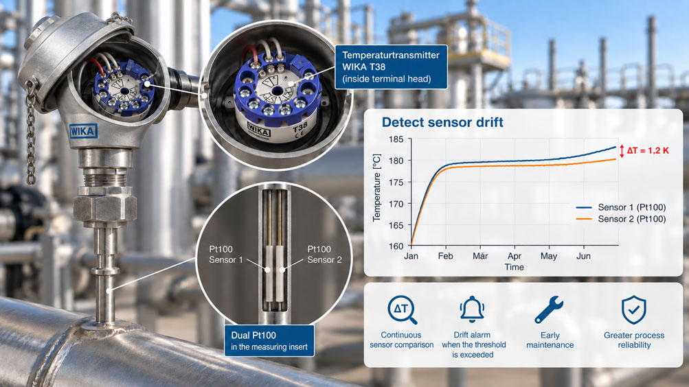
At a critical process measuring point, two Pt100 sensors are installed in the same measuring insert. Both measure almost the same temperature and are evaluated by a temperature transmitter with two sensor inputs. During commissioning, the two measured values differ by only a few tenths of a kelvin. Several months later, however, the difference slowly increases. Sensor 1 may, for example, indicate 180.4 °C while Sensor 2 shows only 179.2 °C.
This is exactly the type of situation in which the drift monitoring function of a modern temperature transmitter can be used. Instead of discovering only during the next calibration that one Pt100 has changed, both sensor signals are continuously compared with each other. If their deviation exceeds a defined threshold for a certain period of time, the transmitter can generate a diagnostic message.
As simple as the principle may sound, correct interpretation is essential. Two different temperature values do not automatically mean that one of the Pt100 sensors is electrically drifting. Differences in heat transfer, lead resistance, mechanical contact within the measuring insert, process gradients or different response times can also create a deviation. And even if sensor drift is actually present, a simple comparison of two equivalent Pt100 sensors can initially determine only that the two values are diverging – not necessarily which sensor is measuring incorrectly.
The most important rule is therefore: Dual-sensor drift monitoring is a diagnostic method, not an automatic calibration. Threshold, delay time, sensor design, wiring and installation conditions must be selected so that normal differences between measured values are not confused with genuine sensor ageing.
How does drift monitoring with two Pt100 sensors work?
A dual Pt100 contains two electrically separate resistance sensors. They are usually installed together in the same measuring insert and therefore measure almost the same thermal condition. However, each Pt100 has its own electrical measuring circuit and can be evaluated separately by a suitable temperature transmitter.
The transmitter first calculates two temperature values from the two resistances:
T1 and T2
For drift monitoring, the difference between them is then evaluated:
ΔT = |T1 - T2|
As long as both sensors behave similarly, this difference remains small. If the resistance characteristic of one sensor begins to change due to ageing, mechanical stress or other influences, the difference can gradually increase.
Modern transmitters with two inputs can continuously monitor this deviation. With the Siemens SITRANS TH420, for example, the absolute difference between the two input values is compared with an adjustable drift threshold. If the difference remains above the threshold longer than the configured drift time, drift is detected.
This turns a simple dual Pt100 into a continuously monitored temperature measuring point. Regular calibration does not become fundamentally unnecessary, but an increasing deviation can become visible between two calibration intervals.
Which temperature difference is monitored?
With conventional dual-sensor monitoring, the absolute temperature value itself is not the primary parameter. What matters is the difference between the two values measured at the same time.
Example:
T1 = 200.2 °C
T2 = 200.4 °C
ΔT = 0.2 K
A later measurement gives:
T1 = 200.3 °C
T2 = 201.5 °C
ΔT = 1.2 K
The increasing difference indicates that something has changed at the measuring point. Initially, however, it is only a diagnostic indicator.
| Observation | Possible cause | Assessment |
|---|---|---|
| Both sensors differ only slightly and consistently | Normal behaviour of the sensors and measuring chain | No immediate indication of drift |
| Difference increases slowly over weeks or months | Ageing or drift of one sensor may be occurring | Monitor the trend and inspect the measuring point |
| Difference changes suddenly | Wiring fault, contact problem, sensor break or process event | Perform electrical and mechanical diagnostics |
| Difference occurs only during rapid temperature changes | Different thermal response times | Check heat transfer and installation conditions |
| Both sensors change almost identically | Real process change or common influence on both sensors | Dual-sensor comparison cannot reliably detect common drift |
A single difference value is therefore less informative than its trend over a longer period. For predictive maintenance, it is particularly useful to know whether the deviation is continuously increasing.
Why a deviation does not automatically mean sensor drift
Two Pt100 sensors can indicate different temperatures even though both are electrically functioning correctly.
Even small differences in thermal coupling can create a deviation. If the two sensor elements are not positioned at exactly the same point or have slightly different contact with the measuring insert, they may respond at different speeds during temperature changes.
Electrical effects may also be involved. Lead resistance, terminals, contact resistance or moisture in the connection head can influence resistance measurement, especially if the wiring configuration is unsuitable.
The process itself is another factor. In a pipeline or vessel, the temperature is not necessarily perfectly homogeneous at every point. Where strong gradients are present, even a small spatial offset between the two sensor elements can produce a real temperature difference.
A drift alarm should therefore always be understood as a prompt for diagnosis – not as automatic proof that Sensor 1 or Sensor 2 must be replaced.
Heat transfer and installation as sources of error
In industrial resistance thermometers, the actual Pt100 is often located inside a measuring insert, which in turn is installed in a thermowell. The process first heats the thermowell, then the measuring insert and finally the sensor element.
This thermal chain inevitably creates a certain delay. Important factors include:
- thermowell diameter and wall thickness,
- insertion depth,
- flow velocity of the medium,
- thermal conductivity of the materials used,
- contact between the measuring insert and the thermowell tip,
- position of the two Pt100 elements within the measuring insert.
A spring-loaded measuring insert is intended to ensure defined contact with the thermowell tip. If the measuring insert is installed incorrectly or is not pressed sufficiently against the bottom of the thermowell, the heat transfer can change.
For drift monitoring, it is particularly important that both sensors have essentially the same thermal path. A dual Pt100 inside a common measuring insert provides favourable conditions because both elements are positioned very close to each other.
Nevertheless, short-term differences can occur during rapid temperature changes. This is precisely why a drift alarm should not be based only on an extremely tight threshold without any time evaluation.
Distinguishing between 2-, 3- and 4-wire connections
A Pt100 is evaluated electrically through its resistance. The connecting leads also have resistance. How strongly this affects the result depends on the connection method used.
With a 2-wire connection, the full lead resistance is included directly in the measured resistance. This configuration is therefore only suitable to a limited extent for precise industrial temperature measurements, particularly with longer cables.
The 3-wire connection largely compensates for lead resistance, provided the resistances of the relevant conductors are sufficiently similar. It is widely used in industrial Pt100 applications.
With 4-wire measurement, current and voltage measurement are separated. This allows the influence of the connecting leads to be eliminated particularly effectively.
| Connection | Influence of lead resistance | Significance for drift monitoring |
|---|---|---|
| 2-wire | Directly affects the measured value | Changes in the wiring can appear as sensor drift |
| 3-wire | Largely compensated when conductor resistances are comparable | Suitable for many industrial dual-sensor applications |
| 4-wire | Lead resistance is largely eliminated by the measurement method | Particularly advantageous for high accuracy requirements |
The Siemens SITRANS TH420, for example, supports two Pt100 inputs using 4-wire technology. Depending on configuration, the WIKA T38 allows two resistance sensors to be connected in up to a 3-wire configuration.
Which version is appropriate depends on the sensor, transmitter, connection head and required accuracy. For a meaningful comparison of two sensors, both should ideally use the same connection method.
Setting a sensible drift threshold
A drift threshold should not simply be set as low as possible. If the threshold is smaller than the normal difference between the two measuring chains, unnecessary diagnostic messages will occur.
In particular, the accuracy of both Pt100 sensors, the transmitter inputs, wiring and thermal installation conditions should be taken into account.
A sensor pair may, for example, normally agree within a few tenths of a kelvin under steady-state conditions but differ more strongly for a short period during rapid temperature changes. A threshold selected only for steady-state conditions could trigger an alarm during every start-up procedure.
The following questions are therefore useful when defining the threshold:
| Question | Why is it relevant? | Effect on parameterisation |
|---|---|---|
| How large is the normal initial difference? | Sensors are not mathematically identical even when new | The threshold must be above normal deviations |
| How dynamic is the process? | Different time constants create temporary differences | Define threshold and delay time together |
| Which process deviation is critical? | Determines the practical value of the drift alarm | Adapt the threshold to quality and safety requirements |
| What accuracy class do the Pt100 sensors have? | Defines part of the normal sensor deviation | Consider measurement uncertainty when selecting the threshold |
| Which connection method is used? | Lead resistances can create additional differences | Do not interpret wiring errors as drift |
| How similar is the heat transfer? | Different thermal coupling produces real ΔT values | Check the installation before setting an excessively tight alarm threshold |
There is therefore no universal threshold such as 0.5 K or 1 K that is optimal for every dual-sensor measuring point. The value must be matched to the specific measurement task.
Why a delay time is important
In addition to the threshold, the period for which the deviation must persist is important.
Imagine a process that heats from 40 to 150 °C within a few seconds. Sensor 1 has a slightly shorter thermal time constant and responds more quickly. During the temperature rise, a temporary difference of 2 K may therefore occur. As soon as the process stabilises, both measured values move closer together again.
Drift monitoring without a delay time could interpret this normal dynamic behaviour as a fault.
For this reason, suitable transmitters provide time evaluation in addition to a difference threshold. With the SITRANS TH420, for example, a drift time can be configured. The corresponding diagnostic message is triggered only if the deviation remains above the threshold longer than this specified period.
However, the delay time should not be set unnecessarily long either. Otherwise, a genuine increasing sensor deviation will only be detected very late.
Threshold and time must therefore be matched together to the dynamics of the measuring point.
Which of the two Pt100 sensors is drifting?
This is one of the most important limitations of a simple dual-sensor comparison.
Sensor 1 indicates 151.0 °C and Sensor 2 indicates 149.5 °C. The difference is 1.5 K. This clearly shows that the two measuring chains no longer agree.
However, these two values alone do not reliably indicate which sensor is providing the correct value.
Possible situations include:
- Sensor 1 is drifting upwards,
- Sensor 2 is drifting downwards,
- both sensors are drifting in different directions,
- one signal path has an additional resistance error,
- the two sensors are actually measuring slightly different temperatures because of heat-transfer effects.
Additional information is required for unambiguous identification. This may be, for example, a calibration against a traceable reference, a third independent sensor or another suitable process reference.
Conventional dual-sensor monitoring therefore primarily answers the question:
“Do the two measurements still agree sufficiently?”
It does not automatically answer:
“Which of the two Pt100 sensors is definitely wrong?”
Why common-mode drift can remain undetected
Another limitation arises from common-mode or same-direction errors.
If both Pt100 sensors age in almost the same way as a result of the same stresses and their characteristics shift in the same direction, the difference between them can remain small.
Example:
When new, both sensors indicate 200.0 °C. After prolonged use, both indicate 201.0 °C even though the actual temperature is still 200.0 °C.
The dual-sensor comparison still gives:
ΔT = 0 K
The measuring point nevertheless has a common error of approximately 1 K.
This example demonstrates why dual-sensor monitoring is not a complete alternative to metrological testing or calibration. It is particularly effective at detecting different behaviour between the two sensors.
Distinguishing drift monitoring from sensor redundancy
Dual sensors are frequently used for both diagnostics and redundancy. However, these two functions should be considered separately.
With drift monitoring, both valid measured values are compared. If their difference exceeds the configured threshold, a diagnostic message is generated.
With a sensor backup function, by contrast, the transmitter uses one sensor as the primary measured-value source. If a clear fault such as wire break or short circuit is detected on this sensor, the transmitter can automatically switch to the second sensor.
A drift alarm represents a more difficult condition than an unambiguous wire break. With a wire break, it is known which input has failed. With a difference between two Pt100 sensors that both continue to produce plausible values, it is not necessarily known which value is correct.
Before commissioning, it should therefore be clearly defined what reaction a drift message should trigger: maintenance information only, an alarm to the control system or another project-specific action.
Further details on the actual redundancy architecture are covered in the article “Planning dual Pt100 redundancy correctly”.
Documenting the initial condition and calibration
Drift monitoring becomes much more informative when the initial condition of both sensors is known.
During commissioning, the difference between Sensor 1 and Sensor 2 under stable process conditions should therefore be documented. Perfectly identical values are not necessary and are not always to be expected in practice.
For high accuracy requirements, the individual Pt100 sensors can be characterised or adjusted. Modern transmitters may support sensor trim or characteristic-curve adjustments for this purpose.
It is important to distinguish between two things: sensor adjustment reduces known systematic deviations. Drift monitoring, by contrast, observes whether the behaviour changes over time.
After replacing a sensor or readjusting the measurement, the new initial condition should therefore also be documented. Otherwise, future trends will be compared with an initial condition that is no longer valid.
Evaluating dynamic temperature changes correctly
A dual Pt100 is particularly informative for drift monitoring when both sensors are compared under steady-state or slowly changing conditions.
During rapid temperature changes, by contrast, the thermal response behaviour becomes visible. Even small differences in position, mass or contact can cause one element to respond several seconds faster than the other.
A characteristic trend is then typically observed:
During a temperature rise, the difference initially increases, reaches a maximum and then decreases again once a steady-state condition is reached.
Genuine long-term drift, by contrast, tends to produce a difference that remains under thermally stable conditions or gradually increases over weeks and months.
For diagnostics, it is therefore very helpful to record not only the alarm state but also both individual values or their difference as a trend in the control system.
Practical example: difference increases over several months
A dual Pt100 is installed in a reactor. Both sensors are evaluated by a temperature transmitter with two inputs. During normal operation, the process temperature is relatively stable at approximately 180 °C.
During commissioning, the difference between the two Pt100 sensors under stable operating conditions is approximately 0.15 K. This condition is documented.
After several months, the trend recording shows:
Sensor 1 = 180.4 °C
Sensor 2 = 179.2 °C
ΔT = 1.2 K
The difference remains present over a longer period even with a stable process and exceeds the project-specific drift threshold.
The transmitter therefore reports a sensor deviation. However, this does not automatically mean that Sensor 1 is incorrect. Sensor 2 may also have drifted downwards.
The measuring point is checked against a reference at the next suitable maintenance opportunity. This identifies which sensor has the relevant deviation.
The key advantage of continuous monitoring is that the change is detected before the next routine calibration is due. Maintenance can be planned rather than being triggered only after an abnormal process value appears.
Systematic diagnostic procedure
When a drift message occurs, a structured test procedure is recommended. This prevents a mechanical or electrical problem from being prematurely interpreted as ageing of the Pt100.
- Check the individual values: Consider Sensor 1, Sensor 2 and their difference separately.
- Evaluate the trend: Has the difference increased slowly or appeared suddenly?
- Check the process condition: Is the temperature currently in a dynamic transition?
- Wait for steady-state conditions: Check whether the difference remains after thermal stabilisation.
- Inspect the wiring: Check terminals, cables and connection resistances.
- Read the transmitter diagnostics: Distinguish wire break, short circuit and wiring faults from drift.
- Check the measuring insert: Verify correct seating and thermal contact.
- Assess the thermowell and installation: Consider deposits, insertion depth and process flow.
- Perform a comparison measurement: If necessary, use a suitable independent reference.
- Calibrate the sensors: Only then can it be determined unambiguously which Pt100 is actually outside the permissible deviation.
- Update the initial condition: Document new reference values after replacement or calibration.
The combination of transmitter diagnostic information and process history is particularly useful. A sudden difference immediately after work on the connection head suggests a different cause from a deviation that has increased continuously over two years.
Distinguishing conventional dual-sensor comparison from True Drift Detection
With conventional dual-sensor drift monitoring, two largely equivalent sensor signals are compared. If their difference becomes too large, a deviation is detected. As described above, however, this alone does not always determine which sensor is actually drifting.
This must be distinguished from WIKA True Drift Detection used with the T38. This function operates with a specially designed thermometer version and an integrated reference element. Sensor and reference are calibrated as a complete system, and the transmitter uses a dedicated algorithm for drift evaluation.
True Drift Detection is therefore not simply another name for comparing two arbitrary Pt100 sensors.
For system planning, it must therefore first be clarified which function is required:
- compare two regular sensors with each other,
- implement sensor redundancy or hot backup,
- or use specialised drift monitoring with a defined reference element.
These functions can complement one another, but they are not technically identical.
Common planning and interpretation errors
Calling every difference between two Pt100 sensors drift
Thermal gradients, different response times and wiring faults can also create a difference.
Setting the drift threshold as low as possible
An excessively tight threshold generates diagnostic messages during normal process dynamics and reduces the usefulness of the monitoring function.
Using no delay time
Short-term differences during rapid temperature changes may then be incorrectly interpreted as a permanent sensor deviation.
Automatically identifying the defective sensor from two different values
The comparison initially shows only that a deviation exists. An additional reference may be required for unambiguous identification.
Ignoring common drift of both sensors
If both Pt100 sensors drift in the same direction, the difference between them can remain small. Regular metrological verification therefore remains relevant.
Equating redundancy with drift monitoring
A second sensor can be used for both comparison and backup. However, an unambiguous failure and a slowly increasing measured-value deviation are different diagnostic conditions.
Comparing different connection methods
If one Pt100 is evaluated using a different wiring configuration or significantly different lead resistances, the measuring chain itself may create an additional difference.
Considering only the transmitter
The complete temperature measuring point includes the process, thermowell, measuring insert, sensor elements, wiring and signal conditioning. Many apparent sensor faults originate outside the actual Pt100.
Suitable temperature measurement technology at ICS Schneider
ICS Schneider Messtechnik offers resistance thermometers and temperature transmitters for the process industry, mechanical and plant engineering and other industrial applications.
The WIKA T38 is a digital HART® temperature transmitter for head or rail mounting. It supports the connection of one or two sensors, sensor redundancy and sensor drift monitoring. With suitable sensor technology, WIKA True Drift Detection is also available.
The Siemens SITRANS TH420 has two independent sensor inputs. In addition to wire-break and short-circuit diagnostics, it supports drift monitoring and hot backup. Two resistance thermometers can also be evaluated using 4-wire technology.
A suitable process sensor is, for example, the WIKA TR10-B. Depending on the version, its spring-loaded and replaceable measuring insert can be configured with Pt100 or Pt1000 elements and also with dual measuring elements.
Temperature measurement technology at ICS Schneider
View resistance thermometers and Pt100 sensors
Further reading: Planning dual Pt100 redundancy correctly
Conclusion
Two Pt100 sensors at the same measuring point can provide more than simply a backup measurement in the event of sensor failure. If both values are continuously recorded by a suitable temperature transmitter, their difference can be used as a diagnostic variable for increasing sensor deviation.
An increasing difference between two Pt100 sensors is a valuable indication that something at the measuring point has changed – but it is not yet conclusive proof of which sensor is drifting.
For the monitoring to work reliably, normal sensor deviation, heat transfer, process dynamics, wiring and transmitter accuracy must be considered when defining the drift threshold. A suitable delay time additionally prevents short-term differences during rapid temperature changes from being interpreted as long-term drift.
The limitations of the method are equally important. Two Pt100 sensors drifting in the same way may continue to indicate almost identical values. Pure difference monitoring therefore does not necessarily replace regular calibration or independent reference testing.
Used correctly, however, dual-sensor monitoring can reveal maintenance requirements significantly earlier. Instead of detecting a sensor change only at the next calibration interval, an increasing deviation is identified during ongoing operation and can be incorporated into maintenance planning in a targeted manner.
FAQ on drift monitoring with a dual Pt100
How does a temperature transmitter detect drift in a dual Pt100?
The transmitter records both sensor values separately and monitors the difference between them. If the difference exceeds a defined threshold, a diagnostic message can be generated.
Which formula is used for comparing the sensors?
In simplified form, the absolute temperature difference is evaluated: ΔT = |T1 - T2|.
Does a larger difference automatically mean that one Pt100 is drifting?
No. Different heat transfer, process gradients, connection resistances or dynamic temperature changes can also produce differences.
Can the transmitter determine which of the two Pt100 sensors is measuring incorrectly?
Not necessarily with a simple comparison of two equivalent Pt100 sensors. It initially detects only that the two values no longer agree sufficiently. An additional reference may be required for unambiguous identification.
What is a sensible drift threshold?
There is no universal value. It must be defined based on sensor tolerance, measurement uncertainty, process requirements, heat transfer and the normal dynamic difference at the specific measuring point.
Why is a drift delay time useful?
During rapid temperature changes, two sensors may temporarily indicate different values because of different thermal time constants. A time delay prevents unnecessary drift alarms caused by such transient conditions.
Can a dual Pt100 detect common drift of both sensors?
Not reliably. If both sensors drift by a similar amount in the same direction, the difference between them may remain small.
Does drift monitoring replace regular calibration?
Not generally. It can detect deviations between the sensors at an early stage, but it does not necessarily replace metrological verification against an independent reference.
What is the difference between drift monitoring and sensor backup?
Drift monitoring compares two valid measured values. With sensor backup, the transmitter automatically switches to the second sensor when an unambiguous failure of the primary sensor is detected.
Is a dual Pt100 automatically a fully redundant temperature measurement?
No. Both sensor elements may share the same measuring insert, thermowell and installation point. These common components remain possible common failure sources.
Is a 4-wire Pt100 better for drift monitoring?
4-wire technology reduces the influence of lead resistance particularly effectively and is therefore advantageous for high accuracy requirements. Whether it is necessary depends on the measuring point, transmitter and required accuracy.
Can a 3-wire connection also be used?
Yes. The 3-wire connection is widely used in industrial Pt100 applications and largely compensates for lead resistance, provided the conductors have comparable resistances.
Why can two Pt100 sensors show different values during a temperature step?
Even small differences in position, thermal contact or mass can result in different response times. Under steady-state conditions, the difference may disappear again.
What is WIKA True Drift Detection?
True Drift Detection is a special WIKA solution combining a dedicated thermometer with a reference element and the T38 temperature transmitter. It is technically different from simply comparing two arbitrary Pt100 sensors.
Can the SITRANS TH420 monitor two Pt100 sensors?
Yes. The TH420 has two independent inputs and supports, among other functions, drift monitoring, sensor backup and two 4-wire RTD connections.
Can the WIKA T38 evaluate two sensors?
Yes. The T38 supports different configurations with one or two sensors and provides functions for redundancy and sensor drift monitoring.
Which information should be checked when a drift message occurs?
Both individual temperatures, the difference trend, process condition, temperature dynamics, wiring, transmitter diagnostics, measuring insert, thermowell and, where necessary, an independent reference measurement should be evaluated together.