


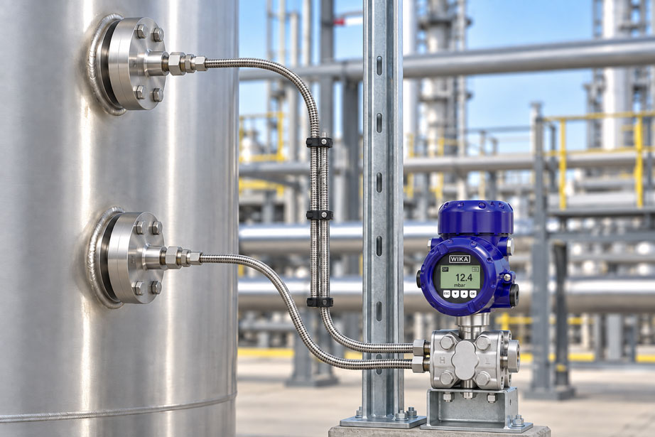
A differential pressure transmitter is connected to a closed process vessel using two diaphragm seals. The lower measuring point detects the pressure from the liquid column and gas space, while the upper measuring point detects the gas-space pressure. Both diaphragm seals are connected to the high- and low-pressure sides of the transmitter via filled capillary lines. On paper, the measuring task is simple: the common gas-space pressure should cancel out, leaving a differential pressure that represents the level.
In practice, however, a second hydraulic system is added. Between the two process diaphragms and the differential pressure transmitter are capillaries filled with a system fill fluid. This fluid has its own density, temperature-dependent volume and viscosity, and it generates hydrostatic pressure components when there are height differences. If, for example, the high-pressure side is routed through a short capillary in the shade while the low-pressure line is several metres longer and is partly heated by a hot process pipe, the transmitter no longer measures only the desired process differential pressure.
Particularly with small differential pressure spans, such additional influences can become significant compared with the actual measuring signal. A highly accurate measuring cell cannot subsequently compensate for an asymmetrically designed diaphragm seal installation.
The key design rule is therefore: With two diaphragm seals, the high- and low-pressure sides must be treated as one complete hydraulic measuring system. Capillary length, capillary diameter, system fill fluid, diaphragm seal design, routing path and thermal environment should be as symmetrical as possible. At the same time, unavoidable hydrostatic height effects must be calculated separately and taken into account in the zero setting or calibration.
How does a differential pressure transmitter with two diaphragm seals work?
A diaphragm seal separates the actual pressure measuring instrument from the process medium. The process side is sealed by an elastic diaphragm. The space behind this diaphragm, the capillary line and the connection up to the measuring cell are completely filled with a system fill fluid.
When process pressure acts on the diaphragm, it is transmitted hydraulically through the fill fluid to the transmitter measuring cell. With a differential pressure transmitter, such a transmission path exists on both the high-pressure and low-pressure sides.
The transmitter then calculates, in simplified form:
Δp = pH - pL
Here, pH represents the pressure arriving at the high-pressure side and pL the pressure at the low-pressure side.
With two diaphragm seals, however, these two values are not determined exclusively by the original process pressures. The properties of the two filled capillary systems also influence the pressures arriving at the transmitter. This is exactly why both sides must be designed together.
When are two diaphragm seals used?
Two diaphragm seals are often used when both the high-pressure and low-pressure sides need to be isolated from a difficult process medium. Typical applications include closed tanks, interface and density measurement, filter monitoring or differential pressure measurements in processes involving hot, aggressive, highly viscous or crystallising media.
For level measurement in a closed tank, the high-pressure diaphragm seal is typically installed at the lower connection. At this point, both the gas-space pressure and the hydrostatic pressure of the liquid column are present. The second diaphragm seal is located at the upper gas-space connection and transmits the gas-space pressure to the low-pressure side.
Ideally:
pbottom = pgas + ρprocess × g × h
ptop = pgas
The common gas-space pressure cancels out when the difference is calculated:
Δp = ρprocess × g × h
However, this simple equation describes only the process side. The liquid-filled capillaries generate additional hydrostatic and thermal effects that must also be taken into account.
What does symmetrical capillary design mean?
Symmetrical design means more than simply ordering two capillaries of the same length. The objective is for both hydraulic transmission systems to react as similarly as possible to changes in their surroundings.
| Influencing factor | Symmetrical design | Problem caused by asymmetry |
|---|---|---|
| Capillary length | Use the same or comparable lengths wherever possible | Different fill volumes and different temperature behaviour |
| Capillary internal diameter | Identical design | Different volumes and dynamic behaviour |
| System fill fluid | Identical fluid on both sides | Different density, expansion and viscosity |
| Diaphragm seals | Preferably the same design and diaphragm geometry | Different volume displacement and temperature behaviour |
| Routing path | Route both lines together wherever possible | Different ambient temperatures |
| Insulation | Treat both sides in the same way | Different temperature gradients |
| Solar radiation | Protect both lines together | One-sided heating creates an additional differential pressure error |
| Mechanical mounting | Comparable, low-vibration routing | Different dynamic behaviour and mechanical loading |
The goal is not absolute geometric perfection. In real installations, the two process connections are often several metres apart. What matters is avoiding additional differences that could otherwise be prevented.
Why equal capillary lengths are useful
The capillary length influences the volume of the system fill fluid. With the same internal diameter, a longer line contains more liquid. If the temperature changes, a larger volume of liquid is therefore also affected by thermal expansion.
If, for example, the high-pressure side is 2 m long and the low-pressure side 8 m long, the two sides no longer react in the same way to a change in ambient temperature. Even if both capillaries were exposed to the same temperature increase, the absolute volume changes would differ because of the different fill volumes.
With identical or comparable capillary lengths, such effects are much more symmetrical. Temperature-induced pressure effects can then occur partly as a common influence and largely cancel out when the differential pressure is calculated.
The word largely is important here. Even two capillaries of exactly the same length do not guarantee complete compensation. The two diaphragm seals may be exposed to different process temperatures, may be installed at different heights or may be affected differently by sunlight, insulation and airflow.
How temperature changes create measurement errors
The system fill fluid is contained in a closed hydraulic system. When it heats up, its volume increases. Since the system cannot expand freely, the diaphragms and measuring cell are subjected to corresponding forces.
The magnitude of this temperature effect depends, among other things, on:
- total volume of the system fill fluid,
- thermal expansion coefficient of the fill fluid,
- temperature change,
- diaphragm diameter and diaphragm stiffness,
- capillary length and diameter,
- measuring span of the differential pressure transmitter.
An absolute temperature-induced pressure error of a few millibar might be barely noticeable with a differential pressure measuring range of several bar. In a level measurement with a span of only a few tens of millibar, however, the same additional pressure can represent a substantial percentage error.
With a symmetrical two-capillary arrangement, the temperature difference between the two sides is therefore particularly critical. If both systems are heated almost identically, equal effects partially cancel out when the differential pressure is calculated. If only one capillary is heated, however, an additional differential pressure component is created immediately.
Consider height differences and hydrostatic offset
A filled capillary line generates hydrostatic pressure like any other liquid column. For a vertical height difference, the following approximation applies:
phyd = ρF × g × h
Where:
- ρF = density of the system fill fluid,
- g = gravitational acceleration,
- h = vertical height difference.
In a closed tank, the two diaphragm seals are normally not installed at the same height. The lower diaphragm seal is located at the lower measuring point, while the second is installed several metres higher at the gas-space connection.
This height difference creates a constant hydrostatic contribution from the fill fluid to the measured differential pressure. It can be calculated during system design and taken into account through zero shift or appropriate calibration.
It is important not to confuse this contribution with an error. A known and stable hydrostatic offset can generally be compensated. It becomes problematic if the density of the system fill fluid changes with temperature or if the actual installation height differs from the planned geometry.
Why equal capillary lengths do not cancel the height effect
A common misunderstanding is that if both capillaries are the same length, their hydrostatic pressure effects cancel completely.
This is not automatically the case.
The hydrostatic effect depends not on the total hose length but on the vertical height difference of the liquid column. A five-metre capillary routed horizontally therefore does not produce the same hydrostatic additional pressure as a five-metre line routed vertically upwards by five metres.
With a tank that has two diaphragm seals installed at different heights, the vertical distance between the upper and lower measuring points remains even if both capillaries are ordered with exactly the same length.
Equal capillary length primarily supports thermal and dynamic symmetry. The hydrostatic zero shift, by contrast, is determined by the density and vertical position of the filled system.
| Influence | Reduced by equal capillary lengths? | Must it be considered separately? |
|---|---|---|
| Different fill volumes | Yes | Normally not, if the systems are otherwise identical |
| Asymmetrical temperature effect caused by different line lengths | Yes | The thermal environment remains relevant |
| Different response times | Yes | Fill fluid and temperature must also be considered |
| Height difference between upper and lower diaphragm seal | No | Yes, as a hydrostatic offset |
| Different exposure to sunlight | No | Yes, minimise through routing and protection |
| Different process temperatures at the two diaphragm seals | No | Yes, take into account during system design |
Selecting the system fill fluid correctly
The system fill fluid is an essential part of the measuring system. It must reliably transmit the process pressure while also being suitable for the intended temperature and pressure range.
Relevant properties include:
- density,
- thermal expansion coefficient,
- viscosity,
- temperature range,
- vapour pressure in vacuum applications,
- physiological properties for food and pharmaceutical applications,
- chemical suitability for the process in the unlikely event of diaphragm damage.
Particularly at low ambient temperatures, high viscosity of the fill fluid can significantly increase the response time. The system may still reach a plausible static final value, but it responds more slowly than expected to rapid process changes.
With two capillaries, the same fill fluid should generally be used on both sides. Two sides filled with different liquids would not only have different densities but also different temperature and dynamic behaviour.
Capillary length and response time
Capillaries influence not only the static measured value. They also change the dynamic behaviour of the system.
When pressure changes, the diaphragm of the diaphragm seal must displace a small volume of liquid. The longer and narrower the capillary and the higher the viscosity of the fill fluid, the greater the hydraulic resistance.
This can damp the measurement. For a slowly changing level, this may be uncritical or even desirable. For rapid differential pressure changes, pump monitoring or control applications, however, an excessively slow measuring chain can become problematic.
Two capillaries of very different lengths can even produce different time constants. During a rapid process step, one side then reaches the transmitter before the other. A temporary differential pressure appears even though it is not present under steady-state conditions.
This is another reason why capillary lengths should be as similar as possible.
Routing capillaries correctly from a mechanical perspective
A capillary line is not an ordinary electrical cable. A kink or mechanical damage changes the internal flow cross-section and can significantly increase the response time or damage the closed diaphragm seal system.
Generous bends should therefore be used during installation and the lines should be mechanically strain-relieved. The capillaries should not support the weight of the diaphragm seal or transmitter.
Low-vibration mounting is equally important. Continuous machine or pipe vibration can act on the capillary and connection points and reduce the service life of the measuring point.
For a two-capillary arrangement, it is advantageous to route both lines together over long sections and secure them using comparable mounting points. This also improves thermal symmetry.
Sunlight, insulation and local heat sources
One of the most common causes of unexpected temperature errors is not the average ambient temperature, but unequal heating of the two capillaries.
A typical example is an outdoor tank. The high-pressure capillary runs on the shaded side of the vessel, while the low-pressure line is exposed to direct sunlight for several hours. Although the nominal ambient air temperature is the same for both sides, the actual capillary temperatures can differ significantly.
Similar effects can be caused by:
- hot steam or process lines,
- furnace walls,
- heater bands,
- cold external walls,
- different insulation,
- strong airflow affecting only one side.
The capillaries should therefore be routed together wherever possible and treated similarly from a thermal perspective. If one line has to be protected or insulated, it should be checked whether the second side can be treated in a comparable way.
A capillary that is insulated only over part of its length can also be problematic. This creates different temperature zones along the line. What matters is not only the average temperature but the complete temperature distribution throughout the fill volume.
Handling zero shift correctly
With a two-diaphragm-seal arrangement, a zero shift does not automatically indicate an installation error. Because of the installation height of the diaphragm seals and the density of the system fill fluid, a significant differential pressure may already exist by design even when the actual process level at the lower measuring point is zero.
This known offset is taken into account when the measuring range is designed. The differential pressure transmitter must be able to cover the complete expected range, including the static capillary effect.
A zero shift becomes problematic when it changes after commissioning depending on the time of day, sunlight or ambient temperature.
Such behaviour strongly indicates a thermal influence from the diaphragm seal system. Simply resetting the transmitter zero does not eliminate the cause. The zero point will shift again the next time the temperature changes.
Practical example on a closed tank
A closed storage tank has a lower process connection and a gas-space connection located three metres higher. Because the medium is aggressive and viscous, both measuring points are to be connected to a differential pressure transmitter using flange-mounted diaphragm seals.
An unfavourable design would use the shortest possible line from each measuring point to the transmitter. The lower capillary might then be 2 m long and the upper one 5 m. In addition, the upper line could be exposed to direct sunlight on the outside of the tank.
The result would be two forms of asymmetry: different fill volumes and different thermal loading. Under changing weather conditions, the indicated level could therefore change even though the actual tank contents remain constant.
A better design uses two technically identical diaphragm seals with the same fill fluid and capillary lengths that are as similar as possible. The lines are routed together for most of the distance to the transmitter and are jointly protected from direct sunlight or local heat sources.
The hydrostatic contribution of the fill fluid caused by the three-metre height difference between the process connections is calculated separately and included in the measuring range or zero-point setting.
This cleanly separates two completely different effects: the geometry-related offset is known and can be compensated. An asymmetrical temperature effect is minimised by design.
Identifying temperature-related errors
A characteristic fault pattern is a level reading that changes over the course of the day even though there is no corresponding process movement. The difference between morning, sunny afternoon and night can be particularly noticeable.
If this behaviour occurs, the differential pressure transmitter measuring cell should not immediately be suspected. Both capillary paths must be examined first.
| Observation | Possible cause | Sensible check |
|---|---|---|
| Measured value changes with sunlight | One-sided heating of one capillary | Compare the temperatures and routing of both sides |
| Indication is very slow when cold | High viscosity of the system fill fluid | Check minimum temperature and selected fill fluid |
| Constant zero shift since installation | Hydrostatic contribution of the fill fluid or installation height | Check the calculation and configuration |
| Zero point changes after insulation work | Asymmetrical thermal treatment of the capillaries | Compare routing and insulation of both sides |
| One side responds significantly more slowly | Different capillary length, kink or restriction | Inspect the capillaries mechanically |
| Measurement error becomes much larger with small spans | System error is too large relative to the useful signal | Redesign the complete diaphragm seal system |
A simple temperature recording along both capillaries can be helpful. Even a few measurement points or a thermographic inspection can reveal whether one line is significantly warmer than the other.
When electronic differential pressure measurement can be useful
With very large distances between the two measuring points or strongly differing ambient temperatures, conventional differential pressure measurement using long capillaries can reach practical limits.
One alternative is electronic differential pressure measurement. In this arrangement, a separate pressure transmitter is installed at each process connection. The two pressure values are combined electrically and the difference is calculated from them.
The advantage is that the several-metre-long connection between the measuring points is no longer filled with system fill fluid. An electrical cable does not produce a comparable hydrostatic or thermal capillary effect.
However, an electronic solution is not automatically better for every application. The two individual pressure measuring ranges, static process pressures and the required small differential pressure must be compatible with one another. For very small differential pressures superimposed on high static pressures, a conventional differential pressure transmitter can offer measurement advantages.
The decision between a conventional two-capillary solution and electronic differential pressure measurement should therefore be based on measuring span, static pressure, distance, process conditions, temperature distribution and required overall accuracy.
Systematic design procedure
For a reliable measuring point with two diaphragm seals, the complete system should be considered together before the equipment is ordered.
- Define the measurement task: Clearly specify differential pressure, level, density, interface or filter monitoring.
- Determine minimum and maximum process pressure: Also consider static pressure on both sides.
- Define the differential pressure span: Specify the useful signal and required accuracy.
- Evaluate the process medium: Consider temperature, viscosity, corrosion, crystallisation and hygienic requirements.
- Select the diaphragm seals: Determine diaphragm diameter, material, process connection and design.
- Select the system fill fluid: Consider temperature range, density, viscosity and process compatibility.
- Record installation heights: Document the height of both diaphragm seals and the transmitter.
- Define capillary lengths: Use identical or comparable lengths wherever possible.
- Plan the routing: Route both capillaries together wherever possible.
- Check the thermal environment: Consider sunlight, steam lines, heaters, insulation and outdoor climate.
- Calculate the hydrostatic offset: Include fill-fluid density and height difference.
- Evaluate response time: Particularly important with long capillaries and low temperatures.
- Check the transmitter measuring range: The useful signal and zero shift must remain within the instrument limits.
- Calibrate the complete system: Treat the diaphragm seals, capillaries and transmitter as one complete measuring chain.
- Document the installation: Record capillary lengths, heights, fill fluid and installation position for later diagnostics.
Common planning and installation errors
Using one short and one long capillary
This creates different fill volumes and different temperature and response-time effects on the high- and low-pressure sides.
Equating equal length with complete compensation
Equal capillary lengths reduce asymmetrical temperature effects. However, the hydrostatic effect caused by different process connection heights remains.
Checking only the transmitter’s temperature accuracy
The temperature compensation of the electronic measuring cell cannot fully correct an asymmetrical temperature gradient in the external diaphragm seal systems.
Insulating one capillary while leaving the other exposed
This deliberately creates different thermal conditions. Wherever possible, both sides should be treated in a comparable way.
Routing one line in sunlight and the other in the shade
This can cause a significant temperature-dependent zero shift, particularly with small differential pressure spans.
Ordering capillaries unnecessarily long “for reserve”
Additional length increases the fill volume and potentially increases temperature and response-time effects. Capillaries should be long enough, but not unnecessarily long.
Coiling excess capillary too tightly
Tight bends and mechanical stress should be avoided. Excess line should be routed securely with a sufficiently large bend radius.
Changing the installation height afterwards
If the transmitter or a diaphragm seal is moved to a different height, the hydrostatic contribution of the filled system changes. The zero point and calibration must then be checked.
Calibrating only the individual instrument
For demanding applications, the relevant measuring chain is the complete system consisting of both diaphragm seals, capillaries and the differential pressure transmitter.
Suitable pressure measurement technology at ICS Schneider
ICS Schneider Messtechnik offers differential pressure transmitters, process transmitters and diaphragm seal systems for level, filter, flow and process measurements.
The WIKA DPT-20 is a differential pressure transmitter for process and industrial applications. In addition to conventional differential pressure, flow and level applications, it can be combined with diaphragm seals for demanding process conditions.
Different diaphragm seals are available for process isolation. Depending on the application, flange, threaded, hygienic or special connections as well as different diaphragm materials and system fill fluids can be used.
The WIKA 990.27, for example, is a flush diaphragm seal with flange connection for aggressive, highly viscous, crystallising or hot media and can be connected to the measuring instrument via a flexible capillary line.
The Siemens SITRANS P320 is also designed for differential pressure and level measurement as well as versions with diaphragm seals.
Process transmitters and differential pressure transmitters at ICS Schneider
Diaphragm seals at ICS Schneider
Conclusion
A differential pressure transmitter with two diaphragm seals is not simply one measuring instrument with two arbitrary connecting lines. Both capillary sides, together with the diaphragm seals, system fill fluid and measuring cell, form one complete hydraulic system.
Capillary lengths that are as equal as possible, identical system components and a comparable thermal environment significantly reduce asymmetrical temperature and dynamic effects. Common routing is particularly important: two capillaries of equal length provide little benefit if one is routed in the shade while the other runs directly alongside a hot process pipe.
At the same time, thermal symmetry must not be confused with elimination of the hydrostatic height effect. The vertical position of the two diaphragm seals produces a defined differential pressure component through the density of the system fill fluid. This offset is calculated and taken into account during zero setting or calibration.
This effect also becomes temperature-dependent because the density and volume of the fill fluid change with temperature. The smaller the actual differential pressure span, the more carefully the complete diaphragm seal system must therefore be designed.
Anyone who considers capillary length, installation height, diaphragm size, system fill fluid, temperature distribution and desired response time together during the planning stage will obtain a much more stable measuring point and avoid apparent transmitter errors whose actual cause lies in the installation.
FAQ on two diaphragm seal capillaries on a differential pressure transmitter
Should both capillaries of a differential pressure transmitter be the same length?
With a conventional dual-diaphragm-seal arrangement, equal or comparable capillary lengths are generally beneficial. This makes the fill volume, temperature behaviour and dynamic response of both sides more similar.
Do the capillaries have to be exactly the same length down to the millimetre?
The technical symmetry of the complete system is what matters. A small difference in length is usually less critical than a major difference or completely different thermal routing. The specific design should be carried out or confirmed by the manufacturer of the diaphragm seal system.
Why does temperature affect a filled capillary?
The system fill fluid changes its volume, density and viscosity with temperature. In a closed hydraulic system, this can create additional pressure effects and changes in response time.
Do temperature effects cancel completely with two identical capillaries?
Not necessarily. Identical systems respond more similarly, but different process or ambient temperatures on the two sides can still create a differential error.
Why should both capillaries be exposed to approximately the same ambient temperature?
The more similarly both sides are heated or cooled, the more the temperature effects occur as a common influence and the less they affect the measured differential pressure.
Can direct sunlight affect the level measurement?
Yes. If only one capillary is heated by direct sunlight, an additional temperature-dependent differential pressure can result.
Do equal capillary lengths cancel the height effect?
No. Hydrostatic pressure depends on the vertical height of the liquid column and its density, not on the total line length.
How is the hydrostatic influence of the system fill fluid calculated?
In simplified form using p = ρ × g × h. The density of the system fill fluid and the vertical height difference are decisive.
Can this hydrostatic offset be compensated?
Yes. A known, stable offset can be taken into account in the measuring range and zero-point setting. The system design must ensure that the complete pressure range remains within the instrument limits.
Why can the offset still change with temperature?
The density of the system fill fluid depends on temperature. If the temperature changes, the hydrostatic pressure of a liquid column also changes slightly.
Does a long capillary affect response time?
Yes. Larger fill volume, smaller capillary diameter and high system fill-fluid viscosity can increase the response time.
Why does a diaphragm seal system respond more slowly at low temperatures?
Many system fill fluids become more viscous as the temperature decreases. This increases the hydraulic resistance of the capillary.
Can a capillary be tightly coiled?
Tight bend radii and kinks should be avoided. The line must be routed without mechanical stress in accordance with the installation requirements of the particular diaphragm seal system.
Can a capillary be shortened afterwards?
A diaphragm seal system is a closed and completely filled measuring system. The capillary length and fill quantity form part of the factory system design. Shortening it on site is therefore not comparable with shortening an electrical cable.
Can the transmitter electronically compensate for the capillary temperature?
The transmitter’s internal temperature compensation primarily applies to its own measuring cell. External asymmetrical temperature effects along the capillaries must already be minimised through mechanical and thermal design.
When is electronic differential pressure measurement an alternative?
It can be attractive when the two measuring points are far apart or when very different thermal conditions are expected for long capillary lines. Whether it is suitable from a measurement perspective depends on the static pressure, differential pressure span and required accuracy.
What information is required for system design?
Required information includes process pressure, differential pressure measuring span, medium, process and ambient temperature, height of the two connections, desired capillary lengths, transmitter position, process connections, materials, desired response time and, where applicable, hygienic or Ex requirements.