


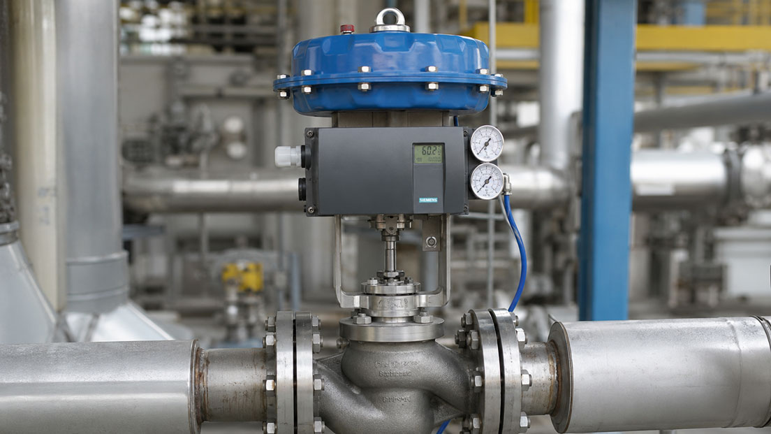
The control valve is supposed to remain constantly at, for example, 45 %. The SIPART PS2 moves to the setpoint, overshoots slightly, corrects back and then begins to oscillate continuously around the desired position.
At first glance, the obvious assumption is:
The positioner is incorrectly configured or defective.
In practice, however, the cause does not necessarily lie in the positioner itself.
An oscillating control valve can be caused, among other things, by:
- static friction or stiction,
- mechanical backlash,
- unfavourable actuator sizing,
- unstable or insufficient instrument air,
- leaks in the pneumatic system,
- unsuitable mechanical linkage,
- incorrect initialisation, or
- interaction with the higher-level process controller
.
Before parameters are changed or the positioner is replaced, it should therefore first be clarified which control loop is actually oscillating: the internal position control loop of the SIPART PS2 or the higher-level process control loop in the PLC or control system.
Products for this area can be found under Siemens process instrumentation. Further field devices are grouped under Field devices for process automation.
Table of Contents
- What does hunting mean on a control valve?
- Distinguishing positioner oscillation from process control loop oscillation
- What is stiction?
- Considering setpoint and actual position together
- Deadband and small valve movements
- Checking mechanical backlash and linkage
- Is the pneumatic actuator suitable for the valve?
- Checking instrument air and supply pressure
- Detecting pneumatic leaks
- Pneumatic or valve block of the positioner
- Correctly assessing auto-initialisation
- When controller parameters should be changed
- Considering valve characteristic and oversizing
- Using SIPART PS2 diagnostic functions
- Distinguishing typical fault patterns
- Recommended troubleshooting procedure step by step
- Practical example: control valve oscillates around 40 %
- Which products and solutions are suitable?
- Conclusion
- Frequently asked questions
What does hunting mean on a control valve?
Hunting refers to repeated oscillation of a final control element around the actual desired position.
For example, the control system requests:
Position setpoint = 50 %
However, the valve repeatedly moves between:
48 % → 52 % → 49 % → 51 % → 48 % …
Depending on the cause, the movement can be very fast or comparatively slow.
Such behaviour is problematic because it:
- mechanically stresses the valve and actuator,
- increases instrument air consumption,
- places additional stress on seals and packing,
- can lead to unstable process values, and
- increases wear throughout the entire valve control chain in the long term.
A continuously active positioner should therefore not automatically be regarded as normal.
However, not every small corrective movement is necessarily a fault. The decisive factors are amplitude, frequency, process requirements and valve design.
Distinguishing positioner oscillation from process control loop oscillation
One of the most important questions is:
Does the position setpoint remain constant or does it also move?
This distinction significantly shortens the troubleshooting process.
| Observation | Likely troubleshooting direction |
|---|---|
| Position setpoint remains constant, actual position oscillates | Check positioner, pneumatics, friction, actuator or mechanics |
| Position setpoint oscillates and actual position follows | Check higher-level process control loop |
| Actual position remains stable, process value oscillates | Investigate process, valve sizing or PID control |
| Position setpoint changes only slightly, valve moves in jumps | Possible stiction, deadband or mechanical friction |
Particularly with an oversized control valve, even a very small change in valve travel can cause a large change in flow.
The process controller then corrects back, the process again responds too strongly and the positioner setpoint begins to oscillate.
In this case, the SIPART PS2 is simply following the valve movements requested by the higher-level controller.
Replacing the positioner would therefore not correct the actual cause.
What is stiction?
Stiction is a combination of the English terms static friction and friction and describes pronounced static friction.
A typical sequence is:
- The controller requests a small position change.
- The actuator builds up force.
- The valve initially does not move because the static friction must first be overcome.
- The actuating force continues to increase.
- The static friction is suddenly overcome.
- The valve jumps beyond the desired position.
- The controller corrects in the opposite direction.
- The sequence repeats.
The result can look like a poorly adjusted positioner.
However, the cause is often mechanical and located in the valve itself.
Typical areas where increased friction can occur include:
- stuffing box or packing,
- valve stem,
- valve plug guide,
- actuator mechanism,
- linkages and joints, and
- bearings of a rotary valve.
Particularly after maintenance work, a stuffing box that has been tightened too much can cause significantly increased static friction.
Considering setpoint and actual position together
For diagnostic purposes, comparing the setpoint and actual position is much more informative than simply observing the valve.
Ideally, the following should be recorded simultaneously:
- position setpoint,
- actual position,
- process value,
- output of the process controller, and
- where applicable, supply or actuator pressure.
A typical stiction pattern can look like this:
The setpoint slowly rises from 40 to 42 %. The actual position initially remains almost unchanged. It then suddenly jumps to 44 %.
The controller then reduces its output again.
This behaviour differs significantly from the smooth, sinusoidal oscillation of a dynamically over-aggressive control loop.
Deadband and small valve movements
A control system should not respond to every minimal measurement deviation with continuous mechanical movement.
An appropriate deadband or suitable sensitivity prevents unnecessary corrections within a small range.
If the effective deadband is too small, the positioner may react to even the smallest changes.
With real valve mechanics involving:
- friction,
- mechanical backlash,
- pneumatic compressibility, and
- limited resolution
this can lead to unnecessarily high positioning activity.
However, an excessively large deadband is also undesirable because the valve will then fail to carry out smaller movements that are actually required.
The objective should therefore not be to calm an oscillating valve simply by increasing the deadband as much as possible.
The actual cause should be identified first.
Checking mechanical backlash and linkage
The positioner can only control the position correctly if that position is actually detected correctly via its feedback mechanism.
Mechanical elements can, however, be located between the positioner and the valve, for example:
- levers,
- followers,
- linkages,
- couplings, or
- shaft connections.
Backlash in this mechanism creates a range in which the positioner or its feedback mechanism moves without the valve position following accordingly.
When the direction changes, this backlash must first be taken up.
This can result in cyclic corrective movement.
The following should therefore be checked:
- secure mounting of the positioner,
- correct installation of the lever,
- appropriate lever length,
- correct position feedback,
- backlash-free couplings, and
- full usable valve travel.
Particularly after replacing a positioner or actuator, the mechanical installation should be checked before a new initialisation is carried out.
Is the pneumatic actuator suitable for the valve?
The actuator also influences control behaviour.
The pneumatic actuator must provide sufficient force or torque to reliably overcome:
- process forces,
- spring forces,
- packing friction, and
- friction within the valve
.
If the available actuating force is only just sufficient, the valve movement can change, particularly at certain process pressures or valve positions.
Another factor is actuator volume.
A very large actuator behaves differently pneumatically from a small actuator.
The air flow capacity of the positioner’s pneumatic system and the volume of the actuator chamber together determine how quickly the actuator can move.
For particularly large actuators, additional pneumatic measures or suitable positioner versions may be useful.
With very small actuators, on the other hand, even a small quantity of air can cause a comparatively rapid position change.
Checking instrument air and supply pressure
The SIPART PS2 is an electropneumatic positioner.
Its control quality therefore depends directly on the pneumatic supply.
The following should be checked:
- supply pressure,
- pressure stability,
- filter condition,
- moisture,
- oil and other contamination,
- air line cross-section, and
- pressure drop during rapid valve movements.
A statically sufficient pressure does not automatically mean that the pressure remains stable during a rapid valve movement.
If, for example, the supply line is too small or an undersized pressure regulator supplies several consumers simultaneously, the pressure may temporarily collapse while the actuator is being filled.
The positioner then attempts to compensate.
This can result in unstable behaviour that may incorrectly be interpreted as electronic controller instability.
Detecting pneumatic leaks
Another possible cause is leakage.
This can occur at:
- hose connections,
- fittings,
- actuator diaphragm,
- piston seals,
- pneumatic block, or
- other pneumatic components.
In the event of a leak, the positioner must continuously supply air in order to maintain the required position.
Depending on the size and characteristics of the leak, this can lead to permanent corrective action.
Significant continuous air consumption at a constant valve position should therefore be investigated.
With double-acting actuators, both chambers and their connections must be considered.
Pneumatic or valve block of the positioner
If the mechanics, actuator and instrument air have been proven to be in proper condition, the positioner’s own pneumatic system must also be considered.
The internal pneumatic block controls the pressurisation and venting of the actuator.
Contaminated instrument air, moisture or wear can impair pneumatic operation.
One possible fault pattern is, for example:
- the valve reaches a position,
- the positioner continues to vent or pressurise noticeably,
- the actual position drifts again, and
- the positioner corrects again.
Before assuming that the pneumatic block is the cause, however, external leaks and actuator operation should be ruled out.
A useful comparison can be to operate the actuator pneumatically independently of the positioner using a suitable safe test procedure.
Correctly assessing auto-initialisation
During initialisation, the SIPART PS2 can adapt to the mechanical characteristics of the connected valve or actuator.
Relevant parameters for positioning are determined during this process.
However, successful initialisation does not automatically mean that the complete valve assembly is mechanically fault-free.
For example, despite successful initialisation, a valve may:
- have increased static friction,
- behave differently under actual process pressure,
- have mechanical backlash, or
- move stiffly only in certain travel ranges.
Initialisation with the process shut down therefore cannot fully predict behaviour under actual operating conditions.
If a valve oscillates after initialisation, it should not automatically be initialised again and again.
Instead, the reason why the control deviation occurs should be investigated.
When controller parameters should be changed
A typical reaction to hunting is to immediately change gain or damping.
This may be necessary in certain cases, but it should not be the first step.
If, for example, the stuffing box is sticking, stronger damping may make the movement appear calmer.
However, the mechanical cause remains.
The following sequence is therefore recommended:
- Check mechanical operation.
- Check instrument air.
- Rule out leaks.
- Check installation and position feedback.
- Check initialisation.
- Analyse the higher-level process control loop.
- Only then optimise controller parameters if necessary.
Which parameters are accessible or sensible to change for a specific SIPART PS2 version should be assessed using the operating instructions and the actual device version.
Considering valve characteristic and oversizing
Not every apparent positioner problem originates in the position control loop.
A significantly oversized control valve is one frequently underestimated factor.
If, for example, a valve operates almost exclusively between 5 and 15 % travel during normal plant operation, even a small change in valve travel can cause a major process change.
The following cycle can then occur:
- The process value deviates slightly.
- The process controller opens the valve slightly.
- The flow changes disproportionately.
- The process value overshoots.
- The controller closes the valve again.
- The cycle repeats.
The positioner may be following its setpoint very precisely.
The hunting then originates in the higher-level control loop.
For diagnostic purposes, the following should therefore also be considered:
- typical valve travel during normal operation,
- valve characteristic,
- valve authority or pressure conditions,
- Kv or Cv sizing, and
- process controller configuration.
A control valve operating at 10 % travel is not automatically incorrectly sized, but in the event of unstable control behaviour it should prompt closer investigation.
Using SIPART PS2 diagnostic functions
A digital positioner offers an important advantage over a purely pneumatic positioner:
It can provide information about the behaviour of the valve control chain.
Depending on device version, communication type and configuration, diagnostic information can be used for condition assessment.
Useful information can include indications relating to:
- valve travel or valve movement,
- control deviations,
- changes in mechanical behaviour,
- valve performance, and
- pneumatic or mechanical abnormalities.
With communication-enabled devices, this information can be integrated into higher-level maintenance or asset management systems.
Trend analysis is particularly helpful.
A single abnormal value often provides little information.
However, if the required positioning activity or mechanical behaviour changes over several weeks, for example, this can indicate increasing wear or friction.
Distinguishing typical fault patterns
| Observation | Possible cause | Recommended check |
|---|---|---|
| Setpoint constant, actual position oscillates evenly | Position control, pneumatics or actuator dynamics | Check mechanics, air supply, initialisation and control behaviour |
| Actual position remains stationary and then jumps beyond the setpoint | Stiction or static friction | Check valve mechanics and stuffing box |
| Setpoint and actual position oscillate together | Higher-level process control loop | Check PID settings and process dynamics |
| Valve oscillates mainly at very small openings | Valve may be oversized or process gain may be high | Check valve sizing and characteristic |
| Position changes with a delay when direction reverses | Mechanical backlash | Check linkage, lever and couplings |
| Supply pressure drops during valve movement | Undersized air supply | Measure dynamic supply pressure |
| Positioner continuously consumes air at constant position | Possible leakage | Check actuator, lines and pneumatics |
| Problem occurs only after valve maintenance | Stuffing box, installation or linkage changed | Compare mechanical condition with previous state |
| Initialisation cannot be completed correctly | Unsuitable travel, installation, air supply or mechanics | Check linkage, end positions and actuator |
| Valve operates correctly with manual pneumatic control but not with the positioner | Positioner pneumatics, feedback or configuration | Specifically check positioner and installation |
Recommended troubleshooting procedure step by step
- Document the oscillation: Record frequency, amplitude and operating condition.
- Observe the setpoint: Check whether the position setpoint remains constant or oscillates itself.
- Compare the actual value: Record position setpoint and actual valve position together.
- Specify a manual position setpoint: If operationally and safely permissible, temporarily remove the higher-level control loop from the diagnosis.
- Check valve mechanics: Investigate stiction, packing friction and stiffness.
- Check linkage: Inspect levers, linkages, couplings and valve travel.
- Assess the actuator: Consider size, spring range and available force or torque.
- Check instrument air: Inspect pressure, quality and dynamic pressure drop.
- Check for leaks: Inspect lines, fittings, actuator and positioner pneumatics.
- Check initialisation: Ensure that installation and valve travel are suitable for correct initialisation.
- Evaluate diagnostic data: Use available SIPART PS2 diagnostic information.
- Assess the process control loop: Consider PID parameters and actual process dynamics.
- Check valve sizing: Analyse normal operating point and required valve travel.
- Only then optimise parameters: Document changes and test their effect in a traceable manner.
Practical example: control valve oscillates around 40 %
A pneumatic control valve in a process water line is positioned using a SIPART PS2.
The control system specifies a constant position setpoint of:
40 %
for an extended period.
However, the actual valve position repeatedly moves between approximately 37 and 43 %.
Initially, it is suspected that the positioner is configured too aggressively.
The diagnosis therefore begins with a comparison between setpoint and actual position.
The setpoint remains constant.
This means that the higher-level process controller can initially be largely ruled out as the direct cause.
The valve is then moved slowly in small increments.
When changing from 40 to 41 %, the valve stem initially hardly moves.
Only after further positioning activity does it suddenly break free and jump to approximately 43 %.
The same behaviour occurs when moving in the opposite direction.
Inspection of the valve mechanics reveals significantly increased friction at the stuffing box.
After the mechanical cause has been corrected properly, the valve is initialised again.
The actual position then follows small setpoint changes much more smoothly.
The oscillation disappears without initially requiring aggressive changes to the internal controller parameters.
The example shows:
Autotuning cannot repair a mechanically faulty valve control chain.
The positioner can only control within the physical capabilities of the valve, actuator and pneumatic system.
Which products and solutions are suitable?
Siemens SIPART PS2 – intelligent electropneumatic positioner
The SIPART PS2 is an intelligent electropneumatic positioner for pneumatic linear and rotary actuators.
It is mounted directly on the valve or actuator and controls the actual valve position to the specified setpoint.
Depending on the device version, various communication and diagnostic options are available.
The SIPART PS2 is therefore particularly suitable for:
- control valves in process plants,
- linear pneumatic actuators,
- rotary actuators,
- 4–20 mA control signals,
- HART applications, and
- digitally integrated asset management and diagnostic concepts.
A key advantage over a purely pneumatic positioner is that additional information about valve behaviour can be used for diagnostics and maintenance.
SIPART PS2 with HART – diagnostics via the existing signal line
For plants using a conventional 4–20 mA signal, a SIPART PS2 version with HART communication can be particularly useful.
In addition to the analogue control signal, additional device and diagnostic information can be transmitted digitally.
This allows an existing measurement or control structure to be expanded with additional diagnostic capabilities without requiring a separate signal line for every item of information.
Analogue 4–20 mA position feedback
For applications in which the actual valve position is to be transmitted separately to the PLC or control system, corresponding analogue feedback options are available depending on the device version or module configuration.
The direct comparison of:
- position setpoint and
- actual position
is particularly useful when diagnosing hunting.
This makes it possible, for example, to quickly determine whether:
- the setpoint is already oscillating from the control system or
- the actual position is unstable despite a constant setpoint.
Pneumatic and spare components for SIPART PS2
Various spare and pneumatic components for the SIPART PS2 are also available within the ICS product range.
However, if a positioner behaves abnormally, the pneumatic block should not be replaced prematurely.
The following should first be checked in particular:
- instrument air,
- external leaks,
- actuator,
- valve mechanics, and
- mechanical feedback
.
Further Siemens components can be found under Siemens process instrumentation and Field devices for process automation.
ICS Schneider Messtechnik supports you in selecting and specifying SIPART PS2 positioners as well as with questions relating to actuators, pneumatics, signal type, position feedback and control valve diagnostics.
Conclusion
If a SIPART PS2 or the connected control valve oscillates, the positioner should not automatically be assumed to be the cause.
The most important first distinction is:
Does the position setpoint oscillate, or only the actual valve position?
With a constant setpoint and unstable actual position, troubleshooting should focus in particular on valve mechanics, stiction, actuator, air supply, leaks, mechanical linkage and initialisation.
Stiction is a particularly common fault.
Due to static friction, the valve initially remains stationary and then, once breakaway force is overcome, jumps beyond the desired position. The positioner then corrects in the opposite direction and cyclic behaviour can occur.
If the setpoint and actual position oscillate together, the higher-level process control loop should be investigated.
Possible causes here include aggressive PID tuning, high process gain or an unfavourably sized control valve.
The automatic initialisation of the SIPART PS2 simplifies commissioning but cannot eliminate mechanical friction, leaks or incorrect valve sizing.
Controller parameters should therefore only be changed after mechanical and pneumatic causes have been ruled out.
The most important rule is:
Do not start by adjusting the positioner – first compare setpoint and actual position and consider the complete control chain consisting of valve, actuator, pneumatics and process.
Frequently asked questions about SIPART PS2 and oscillating control valves
Why does a SIPART PS2 oscillate around the setpoint?
Possible causes include stiction, mechanical backlash, unsuitable actuator dynamics, unstable air supply, pneumatic leaks or unfavourable configuration. The first step should be to check whether the position setpoint remains constant.
What does hunting mean on a control valve?
Hunting refers to repeated oscillation of the valve position around the desired setpoint. The valve continuously corrects in both directions even though a stable position is required.
What is stiction in a control valve?
Stiction is pronounced static friction. Despite a small setpoint change, the valve initially does not move. Once the static friction is overcome, it moves suddenly and can overshoot the desired position.
Can the stuffing box cause hunting?
Yes. Excessive packing friction can cause the valve stem to remain stuck initially and then move suddenly. This should be checked particularly after maintenance work.
Should the SIPART PS2 be reinitialised immediately if hunting occurs?
Not necessarily. Reinitialisation can be useful if the installation has changed or after work on the actuator. However, it does not correct mechanical friction, pneumatic leaks or an unsuitable air supply.
Can poor instrument air affect the positioner?
Yes. Pressure fluctuations, moisture, oil or other contamination can impair pneumatic operation. Air quality and supply pressure should therefore form part of the troubleshooting process.
How can I tell whether the positioner or the process controller is oscillating?
The position setpoint and actual position should be recorded simultaneously. If the setpoint remains constant and only the actual position oscillates, the cause is more likely within the valve control chain. If both oscillate together, the higher-level process control loop should be investigated.
Can an oversized control valve cause hunting?
A significantly oversized valve can create very high process gain. Small changes in valve travel then cause large changes in flow. This can make the higher-level process control loop oscillate even though the positioner is functioning correctly.
Does a larger deadband help against hunting?
An appropriate deadband can reduce unnecessary small valve movements. However, it should not be used merely to mask a mechanical or pneumatic problem.
Which data is particularly useful for diagnostics?
Position setpoint, actual position, process value, process controller output and, where applicable, supply and actuator pressure are particularly useful. A combined trend of these variables makes root-cause analysis considerably easier.