


A Modbus TCP gateway may initially work perfectly after commissioning, but with every additional measuring device and every new visualization, response times become longer. Eventually, sporadic timeouts occur, individual measured values freeze or clients report communication errors even though the Ethernet connection and RS485 wiring are fundamentally correct.
In many cases, the gateway is not defective. Instead, more Modbus transactions are simply being requested than the entire communication chain can process within the available time.
This becomes particularly critical with gateways between Ethernet and a serial RS485 network. On the Ethernet side, several clients can generate requests within a very short time. On the serial side, however, these accesses often have to be transmitted and answered sequentially by the individual Modbus RTU devices.
The available network bandwidth of the Ethernet connection is therefore often not the actual bottleneck in a Modbus TCP/RS485 gateway. The decisive factors are the number of transactions, the response times of the field devices, the serial baud rate, the number of register blocks being queried and the behavior of the clients when timeouts occur.
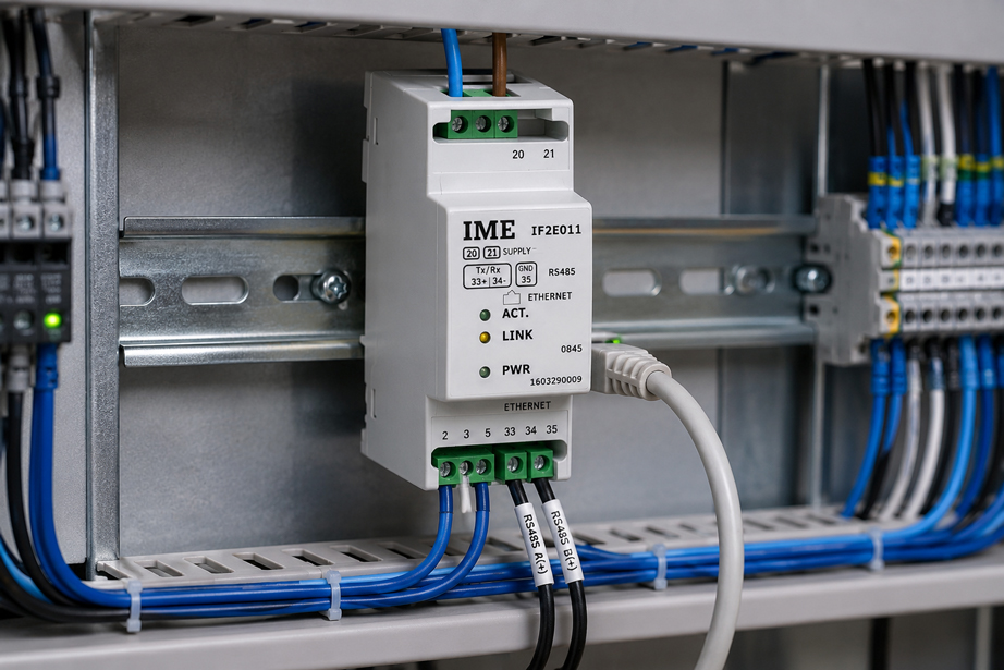
A suitable specific product for such applications is the IF2E011 – Ethernet / RS485 Converter offered by ICS Schneider. It connects Ethernet/TCP-IP communication with an RS485 interface and is therefore suitable for integrating serial measuring devices into an IP-based network.
Additional solutions for higher-level data integration can be found under IIoT Solutions at ICS Schneider.
Table of Contents
- Why can a Modbus TCP gateway become overloaded?
- Why Ethernet and RS485 operate at different speeds
- What is a Modbus transaction?
- What does polling interval mean?
- How many requests are actually generated?
- Combining registers into sensible blocks
- Acquiring measured values at different polling rates
- Correctly accounting for multiple Modbus TCP clients
- Distinguishing TCP connections and transactions
- Do not establish a new TCP connection for every request
- Setting the timeout correctly
- Why too many retries make the problem worse
- Understanding timeout cascades
- Staggering polling over time
- Estimating serial transmission time
- Roughly calculating gateway utilization
- Unit Identifier and device assignment
- Distinguishing network problems from gateway overload
- Systematically diagnosing overload
- Typical error patterns
- Optimizing polling step by step
- Practical example: 20 measuring devices behind one gateway
- IF2E011 at ICS Schneider
- Conclusion
- FAQ
Why can a Modbus TCP gateway become overloaded?
Modbus TCP operates according to a client/server principle. A client sends a request and then expects the corresponding response.
A gateway between Modbus TCP and Modbus RTU has to perform several tasks. It receives the TCP request, interprets the Modbus telegram portion, forwards the communication to the serial side, waits for the response from the addressed RS485 device and then transmits it back to the TCP client.
This brings together two communication environments that operate differently.
New requests can arrive very quickly over Ethernet. On a serial RS485 line, by contrast, only a limited transmission capacity is available.
A typical bottleneck therefore develops according to the following pattern
many fast TCP requests → queue in the gateway → serial processing → longer response times → client timeouts
If retries are then triggered
this can develop into:
timeout → retry → additional request → even longer queue → another timeout
The result
is a communication chain that becomes increasingly overloaded by its own error-handling mechanism.
Why Ethernet and RS485 operate at different speeds
A common misconception is to assess the performance of a gateway based on its Ethernet interface.
With an Ethernet/RS485 gateway, however, the Ethernet side can be considerably faster than the connected serial communication.
Example
An RS485 line operates at:
19.200 bit/s
An Ethernet connection, by contrast
operates several orders of magnitude faster.
This means
The Ethernet client can generate new requests faster than the gateway can have them answered on the serial side.
The actual capacity of the measuring chain is therefore often determined by
- RS485 baud rate,
- telegram length,
- response time of the field device,
- required telegram pauses,
- number of field devices,
- number of register blocks per device.
What is a Modbus transaction?
In the simplest case, a Modbus query consists of a request from the client and a response from the server or field device.
Example
The client wants to read several Holding Registers and sends:
Function Code 03 – Read Holding Registers
The addressed device responds
with the requested register values.
A complete transaction therefore consists, in simplified form, of
Request → Processing → Response
With a gateway, the following is added
TCP Request → Gateway → RTU Request → Field Device → RTU Response → Gateway → TCP Response
The decisive quantity is therefore not only
how many devices are connected
but rather
how many transactions per second are generated
What does polling interval mean?
Modbus is typically not event-driven. A client regularly queries the required values.
This process is referred to as:
polling
.
With a polling interval of 1 second
a defined register range is queried, for example:
1 × per second
At 100 ms
the result is:
10 queries per second
This initially sounds like very little
However, it quickly multiplies with:
- the number of devices,
- the number of register blocks,
- the number of clients.
How many requests are actually generated?
The actual request rate can be estimated approximately.
In simplified form
Requests/s = devices × register blocks per device × polls/s × clients
Example
20 devices are connected.
Each device is read using four separate register queries.
Polling interval:
500 ms = 2 polls/s
A single client therefore generates
20 × 4 × 2 = 160 Requests/s
If a second client independently accesses the same devices
this can theoretically already result in:
320 Requests/s
.
For a serial RS485 line
such a load may be completely unrealistic even though an Ethernet network can transmit this number of small TCP telegrams without difficulty.
Combining registers into sensible blocks
One of the most effective ways to reduce communication load is to optimize register queries.
For example, it would be inefficient
to read five adjacent registers using five individual requests.
It is better
to read a contiguous block if the register model of the field device permits this.
With Function Code 03
according to the Modbus specification, up to:
125 contiguous Holding Registers
can be addressed in a single request.
However, this does not mean
that the largest possible blocks should always be read.
A sensible strategy is
to combine required adjacent values and avoid continuously reading unnecessary registers.
Example
Instead of:
Register 100 → Request 1
Register 101 → Request 2
Register 102 → Request 3
Register 103 → Request 4
it is often possible to use
Registers 100 … 103 → one request
This reduces
the number of transactions by:
75 %
for these four values.
Acquiring measured values at different polling rates
Not every measured value in a system needs to be updated equally often.
A rapidly changing process value may require a significantly higher update rate than a device temperature, operating-hours counter or diagnostic information.
Different classes can, for example, be used as technical starting values
| Data type | Possible starting range | Example |
|---|---|---|
| Fast process value | 100 … 500 ms | Only if the process dynamics actually require it |
| Normal process monitoring | 500 ms … 2 s | Typical visualization |
| Slowly changing measured values | 5 … 30 s | Temperature, energy, operating states |
| Diagnostic information | 10 … 300 s | Device status, operating hours, configuration values |
Important
These values are not specified by Modbus, but are merely possible starting points for system design.
The actual required interval must be derived from:
process dynamics + control requirements + data requirements + available communication performance
.
Correctly accounting for multiple Modbus TCP clients
In modern systems, several systems often access the same Modbus communication.
Examples include
- PLC,
- SCADA,
- visualization,
- historian,
- service PC,
- IIoT data acquisition.
It becomes problematic
when each of these systems independently reads the same registers.
Example
A field device is queried every 500 ms by:
- a PLC,
- a visualization system,
- a data logger.
This can result
in three separate Modbus requests for the same process value.
With a transparent gateway
each of these requests can trigger new communication on the serial side unless the gateway provides corresponding data buffering or caching functionality.
A better architecture can therefore be
Field device → central data collector → multiple consumers
instead of:
Field device ← several independently polling clients
Distinguishing TCP connections and transactions
A TCP connection is not the same as a Modbus transaction.
TCP connection
describes the communication connection between two network devices.
Modbus transaction
describes a single request/response communication within this connection.
A single client can therefore
perform numerous Modbus transactions sequentially over an existing TCP connection.
For the maximum number of TCP connections
there is no universal value that applies to all Modbus TCP devices.
The permissible number depends on the:
- TCP/IP stack,
- RAM,
- processor performance,
- firmware,
- gateway architecture
of the specific device.
The number of Modbus transactions that can be processed simultaneously
is also device-specific.
A high number of connected or reachable devices must therefore not be equated with an arbitrarily high number of parallel requests.
Do not establish a new TCP connection for every request
For cyclic Modbus TCP communication, it is normally more efficient to reuse an existing TCP connection.
It would be inefficient to use
open TCP → read register → close TCP → open TCP → read next register
It is normally better to use
open TCP → several Modbus transactions → keep connection open
This reduces
- additional TCP handshakes,
- connection establishment times,
- additional socket resources
.
This also corresponds
to the general recommendation for Modbus TCP implementations not to establish a new connection for every individual transaction.
Setting the timeout correctly
A Modbus timeout defines how long a client waits for a response to a request.
A timeout that is too short
can cause an otherwise correct response to be evaluated as an error simply because:
- other requests are processed first,
- the serial device responds slowly,
- the gateway has a queue,
- the network adds additional latency.
A timeout that is too long
is also unfavorable.
In this case, a genuinely failed device can unnecessarily block communication for a long time or significantly delay fault detection.
The timeout should therefore be greater than
the expected maximum normal response time
and at the same time short enough
to detect an actual communication failure within the required period.
A universal setting such as
100 ms
or:
1 s
is therefore not correct for every system.
Why too many retries make the problem worse
If a client does not receive a response within the timeout period, it can repeat the request.
A retry is generally useful
because an individual communication attempt may be lost due to a temporary disturbance.
However, it becomes critical
when an already overloaded gateway is operated with very short timeouts and several immediate retries.
The following situation can then occur
Request 1 is still waiting in the queue
→ client timeout
→ retry 1
→ even more queueing
→ second timeout
→ retry 2
The error handling then generates
additional load precisely at the moment when the communication path is already fully utilized.
A better approach is
a coordinated combination of:
- realistic timeout,
- limited number of retries,
- delay between retries,
- clear error handling after several unsuccessful attempts.
Understanding timeout cascades
With several communication levels, different timeouts can be active simultaneously.
Example
SCADA → Modbus TCP Gateway → RS485 Field Device
The following may exist
- TCP client timeout,
- gateway timeout on the serial side,
- response monitoring of the field device,
- client retry mechanism.
These times must be coordinated
If, for example, the gateway internally waits:
500 ms
for a field device, while the higher-level client already sends a retry after:
300 ms
the configuration is unfavorable.
In principle, the following should apply
higher-level timeout > maximum expected processing time of the lower communication level
Staggering polling over time
Even an overall moderate polling rate can cause problems if all clients send their requests at exactly the same time.
A typical case
is a visualization system that simultaneously updates:
50 measuring points
every second.
This creates
a short request burst every second.
It is better
to distribute the queries over time.
For example
Device 1 → t = 0 ms
Device 2 → t = 50 ms
Device 3 → t = 100 ms
...
This
does not necessarily reduce the total number of requests, but it reduces the peak load on the gateway.
Estimating serial transmission time
For a gateway connected to a Modbus RTU line, even a rough timing calculation can show whether a desired polling rate is realistic at all.
At 19.200 bit/s
even the pure transmission of a single byte including start, data and stop bits requires a finite amount of time.
A typical read request
and its response can together contain several dozen bytes.
In simplified form
ttransmission ≈ transmitted bits / baud rate
In addition, there are
- telegram pauses,
- processing time of the slave,
- gateway processing,
- possible waiting times caused by other requests.
As an example
a single complete transaction on a 19.200-bit/s line can easily require on the order of:
20 … 30 ms
or more.
The actual value, however, depends entirely on the telegram length and the device.
At 30 ms per transaction
theoretically:
1 s / 0,03 s ≈ 33 transactions/s
would be possible before additional reserves are taken into account.
Designing exactly to 100 % utilization
is not advisable.
Reserve must be available for:
- varying response times,
- retries,
- diagnostic access,
- temporary network load
.
Roughly calculating gateway utilization
For an initial plausibility check, a simplified utilization calculation can be used.
In simplified form
Utilization ≈ Requests/s × average transaction duration
Example
The system generates:
25 Requests/s
The average serial transaction requires
25 ms
This gives approximately
25 × 0,025 s = 0,625
or:
62,5 %
This value is not the exact gateway CPU utilization
but merely describes what proportion of the available communication time is already being used.
If this value remains close to 100 %
queue formation increases significantly.
For a robust system
communication reserve should therefore be deliberately included in the design.
Unit Identifier and device assignment
With a Modbus TCP/RTU gateway, a TCP request must be assigned to the correct serial device.
The:
Unit Identifier
plays an important role in this process.
With a direct Modbus TCP device
this value may be less relevant depending on the implementation.
With a gateway
however, it can be used to address the downstream Modbus RTU device.
It must therefore be ensured
that:
- every required device address is unique,
- gateway mapping and RTU address match,
- there are no duplicate device addresses.
Incorrect assignment
can cause symptoms similar to overload:
- timeouts,
- sporadically missing values,
- responses from the wrong device.
Distinguishing network problems from gateway overload
Not every Modbus TCP timeout is caused by an excessively high polling rate.
Other possible causes include
- IP address conflicts,
- incorrect subnet configuration,
- unstable switch connection,
- firewall rules,
- VLAN configuration,
- duplicate Modbus addresses on RS485,
- incorrect termination,
- EMC problems on the serial line.
An important diagnostic indication is
if communication improves significantly as soon as the:
polling interval is increased
or:
number of parallel clients is reduced
.
This strongly indicates
that communication load is at least a significant contributor to the problem.
Systematically diagnosing overload
Effective diagnosis begins with an inventory of the communication traffic actually being generated.
The following should be recorded
- number of Modbus TCP clients,
- number of connected field devices,
- polling interval of each client,
- number of requests per polling cycle,
- baud rate of the RS485 side,
- average response time,
- maximum response time,
- timeout setting,
- number of retries.
Then
the polling rate should be reduced step by step.
If, for example
errors occur regularly at:
250 ms
but no longer occur at:
1 s
this is a clear indication of a capacity limit in the communication chain.
Typical errors in overloaded Modbus communication
| Observation | Possible cause | Recommended check |
|---|---|---|
| Measured values update increasingly slowly | Queue in the gateway | Reduce polling rate and number of requests |
| Sporadic timeouts with many measuring points | Communication capacity reached | Calculate total Requests/s |
| Communication works with one client but not with three clients | Multiple polling of the same field devices | Activate clients individually and compare load |
| Timeouts increase sharply after the first error | Retry storm | Check timeout and retry strategy |
| Errors occur periodically every second | Synchronously started polling cycles | Stagger requests over time |
| One slow device affects other devices | Serial communication is blocked by waiting time | Check response time and timeout of this device |
| Many individual registers are being read | Unnecessarily high request count | Create contiguous register blocks |
| Gateway becomes unstable after connecting a service PC | Additional Modbus TCP client increases load | Disable service polling or increase the interval |
| Ethernet is fast, but measured values are still slow | RS485 side is the bottleneck | Calculate serial transaction time |
| High error rate only at 9.600 bit/s | Polling rate does not match serial transmission time | Check baud rate and polling budget |
| Changing the timeout makes the problem worse | Retry mechanism generates additional load | Select timeout greater than the normal maximum response time |
| Some clients lose TCP connections | Connection or resource limit may have been reached | Check the gateway’s maximum client/connection count |
Optimizing polling step by step
- Document the network structure: Record all TCP clients, the gateway and serial devices.
- Determine the RS485 baud rate: The serial side often determines the main throughput.
- Record polling intervals: Consider not only the main client but also SCADA, service and data loggers.
- Count requests per cycle: Record individual registers and register blocks separately.
- Calculate the total request rate: Devices × blocks × polling rate × clients.
- Combine contiguous registers: Where possible, read several required values with one request.
- Remove unnecessary registers: Do not poll diagnostic and configuration data at process speed.
- Classify data by required update rate: Distinguish fast, normal and slow values.
- Increase polling intervals: Query only as fast as the application actually requires.
- Stagger requests over time: Avoid simultaneous load peaks.
- Reduce the number of clients: Use central data acquisition where possible.
- Reuse TCP connections: Do not establish a new connection for every transaction.
- Measure response times: Record both the average and the worst normal case.
- Set the timeout appropriately: Choose it above the normal maximum response time.
- Limit retries: Do not configure aggressive retry loops.
- Check problematic devices separately: One slow RTU device can extend the entire cycle.
- Include communication reserve: Do not operate the system continuously at its theoretical capacity limit.
- Document the optimization: Record polling rate, register ranges, timeouts and retry values.
Practical example: 20 measuring devices behind one gateway
In a system, 20 Modbus RTU measuring devices are connected via RS485 to an Ethernet/RS485 gateway. A SCADA system reads the data via Modbus TCP.
Original configuration
Four separate register ranges are read from each device.
Polling interval:
250 ms
This corresponds to
4 polling cycles/s
The request rate is therefore
20 devices × 4 register blocks × 4 polls/s
= 320 Requests/s
The result
The Ethernet network does not show any unusual utilization, but the following still occur:
- Modbus timeouts,
- outdated measured values,
- sporadic communication alarms
.
During the analysis
it is found that a large proportion of the registers for each device are located directly next to one another.
The four requests are therefore
combined into one sensible contiguous register block.
The new polling rate
for these process values is set to:
1 s
.
This means that only
20 devices × 1 block × 1 poll/s
= 20 Requests/s
are generated.
The number of transactions therefore decreases from
320 Requests/s
to:
20 Requests/s
This corresponds to
a reduction in request rate of:
93,75 %
In addition
slowly changing diagnostic values are only read every 30 seconds and the device queries are distributed over time throughout the cycle.
Result
The communication problems disappear even though neither the gateway nor the RS485 wiring is replaced. The decisive factor was not additional network bandwidth, but a polling strategy adapted to the actual communication chain.
IF2E011 – Ethernet / RS485 Converter at ICS Schneider
For connecting serial RS485 devices to an Ethernet network, ICS Schneider offers the:
IF2E011 – Ethernet / RS485 Converter
as a dedicated product.
For the IF2E011, ICS specifies, among other things
- Ethernet / RS485 conversion,
- TCP/IP communication,
- up to 254 devices in the network per converter,
- auxiliary supply 80 … 270 VAC,
- compact 2-module version for DIN-rail mounting.
Particularly important for the application
is the distinction between:
maximum number of addressable or connected devices
and:
actually achievable update rate
A large possible number of devices does not mean
that all devices can be queried simultaneously at extremely short intervals.
The communication performance that can actually be achieved is still influenced by
- RS485 baud rate,
- response time of the connected devices,
- number of registers,
- polling strategy,
- number of TCP clients,
- timeout and retry settings.
The IF2E011 is therefore particularly suitable
for applications in which existing serial measuring devices are to be integrated via an IP network into:
- visualization systems,
- energy management,
- automation systems,
- higher-level data acquisition
.
For larger installations
the communication architecture should already be designed before commissioning based on the actually required:
devices × registers × update rates × clients
.
Conclusion
A slow or apparently unstable Modbus TCP gateway is not automatically defective. The problem often arises because more requests are generated on the fast Ethernet side than the downstream communication can process in the same amount of time.
The number of devices alone is not sufficient for system design
The decisive factor is:
number of transactions per second
Registers should be grouped sensibly
Several contiguous values can often be read using one shared Modbus request.
Not every value requires the same polling rate
Fast process values and slowly changing diagnostic information should have different update intervals.
Multiple clients multiply the communication load
Especially when each client independently queries the same field devices.
The timeout must match the actual measuring chain
A timeout that is too short generates unnecessary retries. A timeout that is too long, by contrast, delays fault detection.
Retries must be used in a controlled manner
In communication that is already heavily loaded, aggressive retries can make the situation even worse.
The IF2E011 provides a specific Ethernet/RS485 interface
for integrating serial devices into TCP/IP-based networks. However, the available number of devices does not replace proper sizing of the required communication performance.
For practical applications
Record all clients → determine connected devices → check RS485 baud rate → document required registers → combine contiguous registers → calculate actual requests per second → classify data by update requirement → select suitable polling intervals → stagger queries over time → keep TCP connections open where possible → measure actual response times → set timeout above the normal maximum response time → limit retries → provide communication reserve → document changes and then test under actual system load.
FAQ: Correctly Configuring Modbus TCP Gateway, Polling and Timeout
Why is my Modbus TCP gateway becoming slow?
In many cases, more requests are being generated than the gateway or downstream serial communication can process within the available time.
Is Ethernet usually the bottleneck in a Modbus TCP/RTU gateway?
Not necessarily. When bridging to RS485, the serial side with its lower data rate and the response times of the field devices is often the decisive bottleneck.
What does polling mean in Modbus?
A client regularly and actively queries registers from a Modbus device. This cyclic reading process is called polling.
What is a good Modbus polling interval?
There is no universal value. The interval must match the process dynamics and the capacity of the communication path.
Do I have to read every measured value every 100 ms?
No. Many temperature, energy, diagnostic or status values change much more slowly and can therefore be queried less frequently.
How do I calculate the approximate number of Modbus requests?
In simplified form using Requests/s = devices × register blocks per device × polls/s × clients.
Why should I read contiguous registers together?
This can significantly reduce the number of individual Modbus transactions.
How many Holding Registers can Function Code 03 read?
The Modbus specification allows up to 125 contiguous Holding Registers per request with Function Code 03. The specific field device must, of course, also support the requested register range.
Should I therefore always read 125 registers at once?
No. Only sensible contiguous and actually required registers should be combined. Unnecessarily large data blocks increase telegram length and processing effort.
Why do multiple Modbus TCP clients cause problems?
If several clients independently poll the same field devices, the number of requests can multiply.
Is there a fixed maximum number of Modbus TCP clients?
No. The maximum number of simultaneous connections depends on the device and implementation.
Is a TCP connection the same as a Modbus transaction?
No. Many Modbus request/response transactions can be transmitted within one existing TCP connection.
Should the TCP connection be closed after every Modbus request?
Normally not during cyclic communication. Reusing an existing connection reduces unnecessary connection overhead.
What is a Modbus timeout?
The timeout is the amount of time a client waits for a response to a request before evaluating the communication as failed.
How long should the timeout be?
It should be above the maximum expected normal response time of the entire communication chain while still allowing sufficiently fast fault detection.
Does Modbus specify a fixed timeout?
No. The Modbus TCP specification deliberately does not define a universal transaction timeout because network and application conditions can vary considerably.
What happens if the timeout is too short?
Normal but slightly delayed responses are interpreted as errors. This can generate unnecessary retries.
What happens if the timeout is too long?
A failed field device can unnecessarily delay fault detection and, depending on the architecture, further communication processes.
Why can retries additionally overload a gateway?
Every retry generates another request. If a queue already exists, this increases the load even further.
How many retries are reasonable?
This depends on the application. The number should be limited and coordinated with the timeout and fault-handling concept. Aggressive endless retry loops should be avoided.
What is a retry storm?
Several clients reach a timeout at the same time and repeat their requests. This further increases the load and causes even more timeouts.
Why should polling be staggered over time?
So that not all devices are queried simultaneously at the start of a fixed time interval, creating short-term load peaks.
How can I tell whether the RS485 side is the bottleneck?
If communication improves significantly with longer polling intervals, fewer register queries or a higher permissible baud rate, the serial communication capacity is a likely factor.
Can one slow field device affect all the others?
Yes. If the gateway waits a long time for its response, processing of subsequent requests can be delayed.
Why should I poll diagnostic values less frequently?
Many diagnostic values change only slowly. Reading them rapidly in a cyclic manner provides little additional benefit but generates communication load.
Can I acquire Modbus data centrally and then reuse it for several systems?
Yes. Central data acquisition can prevent several higher-level systems from independently polling the same field devices at a high frequency.
What does Modbus Unit Identifier mean?
The Unit Identifier is used, among other things, in gateway applications to assign a Modbus TCP request to a downstream serial device.
Can an incorrect device address look like an overload problem?
Yes. Incorrect or duplicate addresses can cause timeouts and communication errors and must therefore be ruled out before performing a performance analysis.
How can I distinguish gateway overload from a network fault?
Gradually reducing the polling load is useful. If the errors disappear with longer intervals or fewer clients, this indicates a capacity problem.
How much communication reserve should be available?
The system should not be operated continuously close to its theoretical maximum transaction capacity. Reserve is required for varying response times, diagnostic access and retries.
Is the maximum number of devices supported by a gateway the same as the maximum number of devices that can be polled quickly?
No. Device count and achievable update rate are different parameters.
What is the IF2E011?
The IF2E011 offered by ICS Schneider is a converter for Ethernet/RS485 communication with TCP/IP connectivity.
How many devices does ICS specify for the IF2E011?
The ICS product page specifies up to 254 devices in the network per converter. However, the polling rate that can actually be achieved depends on the entire communication architecture.
What supply does the IF2E011 require?
ICS specifies an auxiliary supply of 80 … 270 VAC for the device.
How wide is the IF2E011?
ICS describes the device as a compact 2-module version for control cabinet applications.
Where can I find the IF2E011 at ICS Schneider?
Further information can be found under IF2E011 – Ethernet / RS485 Converter at ICS Schneider.
Where can I find additional IIoT solutions at ICS Schneider?
An overview can be found under IIoT Solutions at ICS Schneider.